Table of Contents
Advertisement
Quick Links
JLZ-1
1000
Colo
or Plo
otter
Inst
tructio
on Ma a nual
Overv
view
Name
e and Functio
on of Each Un
Insta
allation
Com
mmon Basic
Operations
Map
Screen Ope
eration Proc
How
to Use Vari
ious Screen
Func
ction Menus
s
Syst
em Configu
uration Menu
Setti
ng and Exe
cuting Shor
Main
ntenance & I
Inspection
After
r-Sale Servi
ces
Abou
ut Disposal
Spec
cifications
Appe
endix/Refere
ence Materi
1
2
nit
3
4
5
cedure
6
ns
7
8
us
9
rtcuts
10
11
12
13
14
als
Advertisement
Table of Contents

Related Manuals for JRC JLZ-1000


Summary of Contents for JRC JLZ-1000
- Page 1 Overv view Name e and Functio on of Each Un Insta allation mmon Basic Operations Screen Ope eration Proc cedure to Use Vari ious Screen Func ction Menus Syst em Configu uration Menu JLZ-1 1000 Setti ng and Exe cuting Shor rtcuts Main ntenance &...
-
Page 3: Safety Cautions
Safety Cautions Cautions for High Voltage High voltages, ranging from several hundreds to tens of thousands of volts, are used in electronic apparatus, such as radio and radar instruments. These voltages are totally harmless in most operations. However, touching a component inside the unit is very dangerous. (Any person other than authorized service engineers should not maintain, inspect, or adjust the unit.) High voltages on the order of tens of thousand volts are most likely to cause instant deaths from electrical shocks. -
Page 4: Emergency Measures
Emergency Measures Method of First-Aid Treatment Precautions for First-Aid Treatments Apply artificial respiration to the person who collapsed, minimizing moving as much as possible avoiding risks. Once started, artificial respiration should be continued rhythmically. (1) Refrain from touching the patient carelessly as a resultof the accident; the first-aider could suffer from electrical shocks by himself or herself. - Page 5 Flow o of Cardio opulmon nary Res uscitatio on (CPR) A person is co A person is co ollapsing. ollapsing. - Secure the - Secure the safety of the safety of the surrounding a surrounding a area. area. - Prevent se - Prevent se condary disas condary disas...
- Page 6 Speci fic Proce edures fo or Cardio opulmon nary Res suscitatio on (CPR) 1. Che eck the sce ene for safe ety to prev vent second dary disast ters re you OK? a) D Do not touch h the injured or ill person in panic whe en an accide...
- Page 7 b) I If the injured or ill person n is breathing g, place him/h her in the rec covery position and wait for the a arrival of the e emergency services. • • Position t the injured o or ill person on his/her s side, maintai n a clear...
- Page 8 ) Perform ch hest compre essions • Perform m uninterrupt ted chest co ompressions Compress with these parts (the 30 at th e rate of abo out 100 times s per minute heels of both hands). While lo ocking your e elbows posit ioning yours self...
- Page 9 the AED may y not function n. Paste the pads exactly y at the posit tions indicated on the pads, If t the chest is w wet with wate er, wipe dry w with a dry towel and the e like, and th hen paste the e pads.
- Page 10 16. Wh en to stop CPR (Keep p the electr rode pads on.) a) W When the inj ured or ill pe erson has be en handed o over to the em mergency se ervices b) W When the inj ured or ill pe erson has sta arted moanin...
-
Page 11: Table Of Contents
Contents Safety Cautions ............................ i Emergency Measures ......................... ii Contents............................... ix PREFACE ............................xvii Pictorial Marks Used in This Manual ..................xviii Precautions upon Equipment Operation ................... xix EQUIPMENT APPEARANCE ......................xxv List of abbreviations ......................... xxvi Terminology ............................ xxvii How to Use This Manual ........................ - Page 12 4.2.1 Switching the main screen .................... 4-4 4.2.1.1 Switching the main screen ..................4-4 4.2.2 Switching an active screen ................... 4-5 4.2.2.1 Switching an active screen ..................4-5 4.2.3 Switching the Data bar pattern ..................4-5 4.2.3.1 Switching a Data bar pattern .................. 4-5 4.2.4 Details of a status bar ....................
- Page 13 5.5.2 Displaying track details ....................5-9 Drawing lines ........................5-14 5.6.1 Setting a plotting mode ....................5-14 5.6.1.1 Displaying a plotting menu ................... 5-14 5.6.2 Drawing a line ......................5-14 5.6.3 Drawing a polygon ...................... 5-15 5.6.4 Writing characters ....................... 5-16 5.6.5 Deleting graphics and characters ................
- Page 14 5.8.5.1 Displaying a specified route on the map .............. 5-29 5.8.6 Creating a temporary route ..................5-29 5.8.6.1 Canceling route navigation by using a temporary route ........5-30 5.8.7 Creating a temporary destination ................5-30 5.8.7.1 Canceling route navigation to a temporary destination ........5-30 Starting/ending route navigation ..................
- Page 15 6.5.1 Setting the equipment according to the input signals ..........6-12 6.5.1.1 Setting the equipment according to the image signaling system ......6-12 6.5.1.2 Setting the equipment according to the input signal type ........6-12 6.5.2 Adjusting an image quality ..................6-13 Satellite information screen ....................
- Page 16 Setting chart display—Chart menu ..................8-7 Setting a sonar screen—Sonar menu ................. 8-13 Setting GPS—GPS menu ....................8-15 Setting tracks and logs—Track & Log menu ............... 8-17 Setting communication—Comms menu ................8-19 Setting AIS information—AIS menu ..................8-21 8.8.1 Setting a special target ....................8-23 Setting ARPA(TT)—ARPA(TT) menu ..................
- Page 17 11.4 Recommendation of regular inspection and maintenance ..........11-2 Section 12 Disposal ..................12-1 12.1 Disposal of this equipment ....................12-1 12.2 About Chinese version RoHS ..................... 12-2 Section 13 Specifications ................13-1 13.1 Function specification ......................13-1 13.2 Power Supply specification ....................13-3 13.3 Environment conditions .......................
- Page 18 Contents...
-
Page 19: Preface
PREFACE Thank you for purchasing the JLZ-1000 color plotter. When connected to a GPS/DGPS receiver and a GPS navigation system, this color plotter can plot tracks of own ship continuously along with latitude/longitude lines and scale lines. • Before using this equipment, please read this manual carefully to ensure proper use. -
Page 20: Pictorial Marks Used In This Manual
Pictorial Marks Used in This Manual Meanings of Pictorial Marks Pictorial marks are used in this instruction manual and on the product to ensure correct handling of the product and defend you and others' safety and assets. Their meanings are explained below. Fully understand these meanings before starting to read the manual. -
Page 21: Precautions Upon Equipment Operation
Precautions upon Equipment Operation DANGER Never remove the cover of this equipment. Touching the high-voltage section inside will cause an electric shock. Always turn off the power supply switch and disconnect the circuit breaker before implementing inspection, maintenance, part replacement, or for care and cleaning of this equipment. - Page 22 Inspection and repair by anyone other than specialized engineers may result in fire, an electric shock, or malfunction . Please request internal inspection and repair to JRC or a JRC distributor. Before removing or inserting the cable connector to peripheral equipment, be sure to turn off the power.
- Page 23 Notes on using the new pec chart When an SD card of the new pec chart is inserted and the map setting is set to new pec, new pec data is displayed. Do not insert or remove the SD card while the equipment is used. Otherwise, a failure, a malfunction, or an injury may be caused.
- Page 24 Without this measure, this equipment may drop, resulting in a personal injury or property damage. Installation construction of this equipment must not be carried out by any party other than JRC or a distributor of JRC. Installation carried out by anyone other than the specialized engineers may result in a malfunction.
- Page 25 This equipment is intended for use as an aid to navigation only. • The information that is displayed by using through this equipment may not directly fulfill the purpose of navigation. Use a formal chart for navigational judgments. • This equipment does not automatically make judgements on position information. Such judgements must always be made by the operator of the ship.
- Page 26 SD card and USB memory stick Do not attempt to disassemble or tamper with this equipment. Otherwise, fire, an electric shock, or a failure may occur. Do not wet an SD card or a USB memory stick with water, and so on. Otherwise, fire, an electric shock, or a failure may occur.
-
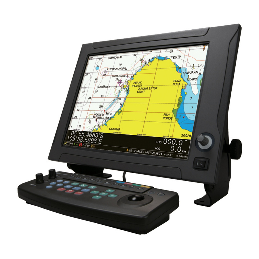
Page 27: Equipment Appearance
EQUIPMENT APPEARANCE Operation Unit Processing Unit... -
Page 28: List Of Abbreviations
List of abbreviations This section describes the main abbreviations that are used for this equipment and related general nautical terms. Alternating Current 交流 Automated External Defibrillator 自動体外式除細動器 Antenna アンテナ Blue 青 bits per second ビット/秒 Course Over the Ground 対地針路 Direct Current 直流... -
Page 29: Terminology
Terminology This section describes the main terms used for this equipment. IEC 60945 Navigation system and radio equipment in general – IEC performance requirements RS422 Technical standard for defining electrical characteristics of balanced digital interface circuits S-VIDEO System for transmitting composite video signals by separating them into two types, brightness signals and color signals SVGA Super Video Graphics Array... -
Page 30: How To Use This Manual
Describes the name and function of each unit of this equipment. Name and Function of Each Unit Section 3 Describes the procedure for installing this equipment by JRC or Installation a distributor of JRC and the cable specification. Section 4... - Page 31 Item Contents Section 13 Describes the main specifications of this equipment. Specifications Section 14 Provides reference materials such as a menu list. Appendix and Reference Materials Notations Keys and switches of the operation unit are represented as shown below. Types of keys and switches Notation Switch with name The switch name is indicated by enclosing with [ ].
-
Page 33: Section 1 Overview Of The Equipment
Section 1 Overview of the Equipment 1.1 Functions • By connecting with the GPS/DGPS receiver or GPS navigation system, this equipment continuously plots the tracks of own ship in color together with latitude and longitude lines, and scales. • This equipment can display and erase tracks by changing the color of the tracks freely. This function is very useful as it enables users to identify the movements of operations intuitively. -
Page 34: Configuration
Merging old operability and new operability: This equipment enables operation and display switching of the new functions while using the layout of the popular current keys. • Color switching by using the display color switch and single-touch mark input • Operation with left and right button clicking sensations in addition to the cursor movement by the trackball •... -
Page 35: Structure
1.4 Structure 1.4.1 NCH-748 operation unit Size: 290 x 123 x 42.5 mm Weight: About 1.1 kg 付録 Section 1 Overview of the Equipment... -
Page 36: Ndc-1752 Processing Unit
1.4.2 NDC-1752 processing unit Size: 340 x 233.8 x 94.7 mm Weight: About 2.2 kg *1 Warning nameplate Section 1 Overview of the Equipment... -
Page 37: Comprehensive System Diagram
1.5 Comprehensive system diagram NWZ-157-J NCH-748 Display Operation unit GPS antenna NAY-1200 DGPS receiver JLR-4341 GPS receiver JLR-4340 (MEDIA cable) CCTV S-VIDEO DC12/24/32V VIDEO MEDIA BOARD USB memory NDC-1752 Navionics SD CARD Map card Processing unit Transducer TRANSDUCER (600W/1kW) EVENT/ NMEA POWER BUZZ... - Page 38 Section 1 Overview of the Equipment...
-
Page 39: Section 2 Name And Function Of Each Unit
Section 2 Name and Function of Each Unit 2.1 NCH-748 operation unit ⑥ [21] [20] [19] [18] [17] [16] [15] [14] [13] [12] [11] [10] Function Keys and others Normal operation Holding down [COLOR] Colour display Select a mark or track color by turning it to the left or the right. Active screen Switches the active screen on Displays the page menu... - Page 40 Function Keys and others Normal operation Holding down End point Sets the end point of the temporary route or temporary destination. Route Starts route navigation. Registers a new route. Starting point Sets a waypoint of the temporary route. Mark Switches the mark color. Registers a mark on the own ship’s position.
-
Page 41: Ndc-1752 Processing Unit
2.2 NDC-1752 processing unit Front SD card USB memory Back CCTV External equipment External event S-VIDEO Fuse (Serial communication) External buzzer (CFQ-7517) NMEA2000 Antenna holder Ground Power supply input Operation unit Transducer Display unit supported receiver (CFQ-7516) (NCH-748) (Analog RGB) 付録... - Page 42 Section 2 Name and Function of Each Unit...
-
Page 43: Section 3 Installation
Section 3 Installation This equipment must not be installed by any party other than JRC and agents of JRC. Installation that is carried out by anyone other than specialized maintenance staff may result in an operation fault. 付録 Section 3 Installation... -
Page 44: Installing The Equipment
3.1 Installing the equipment 3.1.1 Installing the processing unit 3.1.1.1 Selecting an installation location For floor-mounting installation, it is recommended to install in the following area. Maintenance/ cable space Maintenance space Maintenance space Maintenance space Top view Maintenance space Front view NDC-1752 processing unit Unit: mm... -
Page 45: Floor-Mounting Installation
3.1.1.2 Floor-mounting installation Fix the equipment according to the following procedure. Make screw holes on the area where the equipment is to be installed. Fix the equipment by using screws. Mounting hole Mounting hole NDC-1752 processing unit Unit: mm SD/USB slot insertion port Mounting screw hole size 付録... -
Page 46: Wall-Mounting Installation
3.1.1.3 Wall-mounting installation For wall-mounting installation, it is recommended to mount the SD/USB slot facing the ceiling. Ceiling side SD/USB Slot insertion port Various cables Floor side Section 3 Installation... -
Page 47: Installing An Operation Unit
3.1.2 Installing an operation unit Fix the equipment according to the following procedure. Attach one side of the Velcro tape on the equipment. Attach the Velcro tape of the opposite side, matching the Velcro tape on the equipment. Remove the paper from the Velcro tapes and attach the equipment on the structure of the ship. - Page 48 Flush-mounting installation 4-Ø5 Unit: mm Section 3 Installation...
-
Page 49: Connecting Cables
3.2 Connecting cables Connecting a power supply cable POWER Power supply cable: CFQ-7516 (attached) Pin number Name Description 1 (White) Power DCIN + Connect the attached power supply cable. supply input The power voltage distance is 11V to 35VDC. 2 (Black) DCIN- 3 (Green) In this equipment, overvoltage protection functions at the input voltage distance from 35VDC to 36VDC... - Page 50 Connecting GND Thumbscrew for fixing a full ground wire Size: M4 screw The processing unit must be connected to the ground of the ship’s structure for the continuous stable operation. Connect to the ground of the ship’s structure from the fixing thumbscrew. ...
- Page 51 Connecting a keyboard cable KEYBOARD Keyboard cable: Install in NCH-748 10 11 12 13 14 Pin No. Name Description Power Signal for turning on/off the power supply supply On/Off Unused Processing unit Operation unit Data TXD232 Unused Processing unit Operation unit Data RXD232 Unused...
- Page 52 Connecting a video signal cable VIDEO 5 4 3 2 1 10 9 8 7 6 15 14 13 12 11 Pin No. Name Description Outputs a video red signal Green Outputs a green video signal Blue Outputs a blue video signal Unused Unused Unused...
- Page 53 Monitor resolution setting procedure Note Before changing the resolution, remove the power supply cable from the processing unit. Open the cover of the processing unit (remove six screws from the top the cover). Set as follows according to the resolution of the monitor to be connected. CMJ-954 main board Setting part number SW3...
- Page 54 Connecting a GPS receiver DGPS/GPS sensor: JLR-4341/4340 (optional) GPS connection cable: CFQ-9000 (optional) Pin No. Name Description Power supplied from the processing unit to the +12V operation unit Processing unit GPS receiver (return wire) Data COM RXD- Processing unit GPS receiver Data input RXD+ Processing unit ...
- Page 55 Connecting external equipment Pin No. Name Description RS422 input Inputs data. (The setting can be changed by selecting [System Configuration] - [Communication] - [NMEA0183-Port1].) RS422 output Outputs data. (The setting can be changed by selecting [System Configuration] – [Communication] – [NMEA0183-Port1].) Inputs/outputs RS232C (Parallel connection with RSR422 pins of numbers...
- Page 56 Pin No. Name Description RS422 output Outputs 4 data items in parallel. (The setting can be changed by selecting RS422 output [System Configuration] – [Communication] - [NMEA0183-Port2].) RS422 output RS422 output RS422 input Inputs data. (The setting can be changed by selecting [System Configuration] –...
- Page 57 Connecting an external event/external buzzer (log pulse) Pin No. Name Description External EXTBZ- Outputs according to the specification that is set in buzzer “contact output”. EXTBZ+ pulse (The setting can be changed by selecting [System Configuration] – [Others] – [External port set].) External EVENT Enables input of an event mark.
- Page 58 Terminal block (TB1, TB2, TB3) installation procedure Press the button with a flathead screw driver. Insert a cable in the cable insertion port. Fix the connector (M2.5 screws: 2). Cable specification Conductor cross 0.5 - 2.5 mm section Strip length 8 - 9 mm Flathead screw driver...
- Page 59 Connecting CCTV/S-VIDEO MEDIA ① ⑧ ② ⑨ ⑦ MEDIA cable: CFQ-7517 (optional) ⑪ ⑫ ③ ⑩ ⑥ ④ ⑤ Pin No. Name Description Connect a commercial cable by connecting a +12V_GND MEDIA cable. AUDIO_GND AUDIO_IN_R AUDIO_OUT_L AUDIO_GND +12V VIDEO_GND VIDEO_GND VIDEO_IN1 AUDIO_OUT_R AUDIO_IN_L...
- Page 60 Connecting NMEA2000 NMEA2000 Micro type connector Pin No. Name Description Outputs data with the specification that is set in “NMEA2000”. Power V+ NET-S (The setting can be changed by selecting [System Power V- NET-C Configuration] – [Communication] – CAN-H NET-H [NMEA2000]).
- Page 61 Connecting a GPS antenna GPS ANT (TNC type connector) NAY-1200 GPS antenna (Optional) Screw adapter Mounting band Screw Ship’s pole Rubber cap (φ 30mm or less) Attach the mounting band attached to NAY-1200 to pole diameter φ 30mm or less. When disconnecting the cable from the GPS antenna, remove it in the following order.
- Page 62 Connecting a transducer TRANSDUCER Transducer 600W :CFT-2505KZ (optional) Transducer 1kW :CFT-2510KZ (optional) Pin No. Name Description Outputs a high voltage (+) to the transducer. TEMP Detects a water temperature (thermistor). Unused TEMP Detects a water temperature (thermistor). Outputs a high voltage (-) to the transducer. TD GND GND of a high voltage of the transducer Unused...
-
Page 63: Connecting A Card
3.3 Connecting a card Remove the rubber cover from SD/USB and insert a SD card or USB memory . The SD card slot applies a push-in/push-out mode. When inserting a card, insert properly until a click sound is heard. ... - Page 64 Section 3 Installation 3-22...
-
Page 65: Section 4 Basic Operation
Use the following procedure to turn on the power supply. Turn the [POWER] switch to the right side ([ON] side). The power supply is turned on and the initial screen is displayed. Type JLZ-1000 Program Version 01.00 2017-xx-xx FPGA Version... -
Page 66: Turning Off The Power Supply
Display a GPS signal reception state When this equipment starts, an icon that indicates the reception state of the signals from the GPS satellite is displayed at the left end of the status bar (see Section 4.2 “How to interpret the screen”). Status bar Icon that shows the GPS signal reception state... - Page 67 4.2 How to interpret the screen The screen of this equipment comprises the following areas. Compass area Main screen Chart level No. of recorded points Data bar Status bar Each area is outlined below. Area Description Compass area • The ship’s heading (HDG)/course over the ground (COG) is displayed at the center.
-
Page 68: Switching The Main Screen
[Example 3: Splitting a screen into 4 4.2.1 Switching main segments] screen • Displays a map screen on the top left side, a main screen, multiple screens data screen on the bottom left side, a comprising 2 to 4 screens can be displayed as highway screen on the top right side, and a well as a single screen such as a map screen depth screen on the bottom right side. -
Page 69: Switching An Active Screen
4.2.2 Switching active 4.2.3 Switching the Data bar screen pattern At split screen display, the screen that is The data bar consists of two display areas. operated is called an active screen. The upper data bar (layout) displays is fixed. The active screen is enclosed by an orange The lower data bar is switched from three frame. -
Page 70: Details Of A Status Bar
4.2.4 Details of a status bar The following information is displayed on the status bar. [1] GPS positioning status Displays the GPS positioning state in one of the following colors. Red: The equipment is searching for signals from the GPs satellite. Yellow: The GPS positioning accuracy is low. - Page 71 [7) Bearing mode Displays the current bearing mode. The following bearing modes can be selected depending on the motion mode. Motion mode Bearing mode True motion N-UP, S-UP, W-UP, and E-UP Relative mode N-UP, C-UP, H-UP, and WP-UP [8] Main screen number Displays the number of the main screen that is currently displayed (P.H, P.1 to P.9).
-
Page 72: Switching A Screen Brightness
4.3 Switching a screen brightness A screen brightness of the equipment can be switched between a day screen and a night screen. To switch the screen brightness, press the (Day/Night) key. Whenever the key is pressed, the mode switches between the day mode and the night mode. 4.4 Changing the setting on the menu This equipment has the System Configuration menu that is used for setting various equipment modes and status at power-on, a function menu for setting specific to each screen, and a page menu for... -
Page 73: Operating The System Configuration Menu/Function Menu
4.4.2 Operating the System Configuration menu/function menu 4.4.2.1 Menu levels ► When the mark is attached on the right side of the menu item that is displayed, there is a following level. 4.4.2.2 Keys that are used for menu operations Use the following keys when setting by menu operations. -
Page 74: Example Of Menu Operations
4.4.2.3 Example of menu operations This section shows the procedure for setting to add water temperature display by using the System Configuration menu. Hold down the (Menu) key. The System Configuration menu is displayed. Press the (Center), (Right), key. A screen for setting to enable/disable the data to be added to the track is displayed. -
Page 75: Section 5 Map Screen Operation Procedure
Section 5 Map Screen Operation Procedure This Section describes the main procedure of Example: The unit of the distance is nm and the the map screen. length of the scale bar is 10nm. Map card and screen Press the (Zoom In) key or the (Zoom Out) key. -
Page 76: Switching A Scale To A Preset Scale
5.2.3 Moving a map Select a preset number whose scale value is to be changed. 5.2.3.1 Moving a map by using the Select one of the values from Preset scale 1 to Preset scale 10. (Up/Down/Left/Right) keys (Center), (Right) When any of the Press the (Up/Down/Left/Right) keys are pressed, the key. -
Page 77: Setting A Chart Level
Hold down the (Menu) key. 5.2.4.1 Setting a chart level The System Configuration menu is Memo displayed. When the map is new pec, three chart levels are set as follows at the factory delivery.. ○:Display ×:Undisplay Information Chart level Lat/Lon grid ○... -
Page 78: Switching A Chart Level
5.2.4.2 Switching a chart level Select the chart level whose setting is to be changed and press the Hold down the (Menu) key. (Center), (Right), or key. The System Configuration menu is Select one of levels from Chart lever displayed. page1 to Chart lever page3. -
Page 79: Switching A Bearing Mode
Select a required chart level (one of Memo page 1 to page 3) and confirm the The motion mode is set to [True motion] at selection by pressing the the factory delivery. (Center), (Right), or key. For switching of a motion mode, see the “Motion mode”... -
Page 80: Using Parallel Index Cursor / Circular Cursor
5.3.1.1 Operating a variable cursor Using parallel index Changing the width of the measurement range (interval of the parallel index cursor cursor / circular cursor and the diameter of the circular cursor) In this system, two measuring tools can be Use the (Up and Down) keys. -
Page 81: Selecting A Color Of A Mark/Track
5.4.2 Selecting a track color Selecting a color of a Any of seven colors or Off can be set for a track. mark/track When the track is set to Off, the mark track is 5.4.1 Selecting a color of a not registered. -
Page 82: Setting The Details Of Track & Log Display
The [Tracks] menu can be displayed by using Setting the details of the following procedure also. Track & Log display Hold down the (Menu) key. Details can be set for a track such as the The System Configuration menu is interval for placing dots that comprise the track displayed. -
Page 83: Contents
5.5.2 Displaying track details Select an item to be set in the [Tracks] menu and set as required. The following table shows the setting contents and setting value of each item in the [Tracks] menu. Item Setting contents Setting value (Underline: Default value) Display Set whether the track is displayed on... - Page 84 Item Setting contents Setting value (Underline: Default value) Time Set whether a time is to be added to the Enable track. Disable When a check mark is attached, the item is enabled and when the check mark is removed, the item is disabled. Temperature Temperature1 Set a temperature within the range from...
- Page 85 Item Setting contents Setting value (Underline: Default value) Depth Depth1 Set a depth range from Depth1 to Depth1: Depth2 Depth7. 10m to (Minimum depth of Depth2 1m) Depth3 The depth range that can be set from Depth4 Depth1 to Depth7 is from 10m to 999m Depth2: Depth5 in 1m units.
- Page 86 Item Setting contents Setting value (Underline: Default value) Maximum current Set a maximum current value to be attached 0.10kn to 5.00kn to 9.99kn to the track. Setting a maximum current value Select a digit to be set by using (Left/Right) keys and select a value by using the (Up/Down) keys.
- Page 87 Item Setting contents Setting value (Underline: Default value) Time Set an interval for recording a track 1s./2s./5s./10s./20s./30s./ with time or distance. 1m./2m./5m./10m./20m./ 30m./60m./0.01/0.02/0.05/ 0.1/0.2/0.5/1.0/2.0/5.0/ 10.0 Delete Delete all the tracks that are displayed. track When this item is selected, [Yes] [No] is displayed.
-
Page 88: Drawing Lines
[1] Number of endpoints of the line Drawing lines that is currently drawn. This information indicates the number of The plotting function of this equipment enables points that have been drawn out of the following: 50,000 points in maximum. • Draw a line on a map. -
Page 89: Drawing A Polygon
Select a required color and confirm 5.6.3 Drawing a polygon the selection by pressing the (Center), (Right), or key. Set a plotting mode and display a plotting menu. Close the menu by pressing the See Section 5.6.1 “Setting a plotting key. -
Page 90: Writing Characters
keys and confirm the selection by To increase the number of vertices, pressing the (Center) key. move the cursor to the next vertex Create a required character string by and press the key. repeating this operation. Draw a required polygon by repeating To modify the character that has been this procedure. -
Page 91: Deleting A Specified Line And A Polygon
5.6.5.2 Deleting a specified line Selected line: Delete all one line. Connect: Delete the selected point and a polygon and lines, and connect adjacent A line, a broken line, or a polygon can be points. deleted by specifying it. Disconnect: Delete the selected point There are two ways to delete. -
Page 92: Drawing Lines While Entering Latitude And Longitude
Select [Delete all text] and confirm the selection. A confirmation message is displayed. Confirm the selection by selecting [Yes]. When inserting the continuation point, move the cursor to the line to be 5.6.6 Drawing lines while inserted and select [Insert] to add a entering latitude and line. -
Page 93: Registering A Mark (Destination)
[1] Name of the mark Registering a mark [2] Mark registration date and time [3] Latitude/longitude (current cursor (destination) position) By registering a mark on the map, a mark can [4] Mark shape be set on any position. [5] Mark color In this equipment, a mark can also be used by a [6] [Danger] setting destination (waypoint or final destination) of a... -
Page 94: Registering A Mark At The Own Ship's Position
Close the page menu by pressing Select [Create] and confirm the key. selection by pressing the (Center), (Right), or key. 5.7.2 Registering a mark at the The [Create waypoint] screen is own ship’s position displayed. This screen is the same as that A mark can be registered at the own ship’s displayed when [New waypoint] is position on the map with a simple key... -
Page 95: Moving A Mark
Select [Edit] and confirm the Move the cursor to the target selection by pressing the position of the mark and press the (Center), (Right), or key. key. The [Create waypoint] screen is displayed. 5.7.4 Deleting a mark The registered mark is retained even if the power supply of the equipment is turned off. -
Page 96: Deleting All The Marks
Press [Yes] and confirm the selection by pressing the (Center) or key. All the marks are deleted from the [Waypoints] list and the map. To cancel the deletion, select [No] and determine the cancellation. Select [Delete] and confirm the selection by pressing the 5.7.5 Other operation (Center), (Right), or... -
Page 97: Sorting Marks
Select [Waypoints] by using the Hold down the (Screen) key. (Left/Right) keys and press A page menu is displayed. (Center) or key. Select [Waypoints] by using the The registered marks are displayed in (Left/Right) keys and press the list. (Center) or key. -
Page 98: Displaying Only The Marks Registered During The Specified Period
5.7.5.4 Displaying only the marks Select [Start date] in the following line and press the (Center), registered during the (Right), or key. specified period By specifying a range of the mark registration dates, the marks that were registered outside of the range can be hidden on the map (filter function). -
Page 99: Setting A Route
To change the route name, select a Setting a route character to be changed by using (Left/Right) keys, A route refers to a Sea Lane with waypoints set change the character by using the between the starting point and the destination. (Up/Down) keys, and Route navigation is the method where a route is confirm the change by pressing the... -
Page 100: Creating A Route By Connecting Marks
keys, change the character by Close the page menu by pressing using the (Up/Down) keys, key. and confirm the change by pressing the (Center) key or 5.8.2 Creating a route by key. connecting marks Press the (Down) key, select When a mark has already been registered, a the 1 row of the list, and confirm route can be set by using the own ship’s... -
Page 101: Editing A Route
S elect a character to be changed Close the page menu by pressing by using the (Left/Right) key. keys, change the character by using the (Up/Down) keys, 5.8.3 Editing a route and confirm the change by A route name can be changed or a new pressing the (Center) key or waypoint can be inserted, or a waypoint can be... -
Page 102: Deleting A Waypoint
A page menu is displayed. The route editing ends. Select [Routes] by using the Close the page menu by pressing (Left/Right) keys and press the key. (Center) or key. 5.8.4 Deleting a route Select a route to be edited, press (Menu) key, select [Edit on The route that has been set is kept even if the chart] from the menu that is... -
Page 103: Deleting All The Routes
5.8.4.2 Deleting all the routes Memo 5.8.6 Creating a temporary When there is a route that is being used by route route navigation, this operation is disabled. A temporary route is not stored in the End route navigation before deleting all the equipment. -
Page 104: Canceling Route Navigation By Using A Temporary Route
5.8.6.1 Canceling route navigation Starting/ending route by using a temporary route navigation Press the (Menu) key, select [Cancel route] from the menu that is displayed, and 5.9.1 Starting route navigation confirm the selection by using the (Center), If one or more routes are set, route navigation (Right), or key. -
Page 105: Starting Route Navigation From The Route List
Route navigation starts by using the 5.9.1.3 Map screen during route selected route. navigation During the route navigation, own ship and the 5.9.1.2 Starting route navigation route are displayed as shown below. from the route list Own ship Arrival circle Hold down the (Screen) key. -
Page 106: Operating A Route
5.9.2.2 Re-setting a cross-track error XTE alarm XTE is re-set from the position where the An alarm is issued when own ship entered into following operations are executed. or exited from the route width. Memo In this case, one of the following icons is At the factory delivery, the route width that displayed on the status bar. -
Page 107: Switching A Map
5.10 Select [System Configuration] Switching a map and confirm the selection by When both of a new pec card and a Navionics pressing the (Center), card are inserted, the map to be displayed can (Right), or key. be switched in the following procedure. The [System Configuration] menu is displayed. - Page 108 Section 5 Map Screen Operation Procedure 5-34...
-
Page 109: Section 6 How To Use Various Screens
Section 6 How to Use Various Screens This section describes how to customize screens and how to interpret and use the screens other than the map screen. Noations of the operation procedure In this Section, the menu operation procedures may be described by simplifying them according to the following notation standards. - Page 110 Page menu buttons When the (Active screen) key is held down, the following page menu is displayed. When the (Screen) key is pressed, the following page menu is displayed. Each button in the page menu is expressed as follows in this manual. Button Notation Button...
-
Page 111: Customizing Screens
6.1 Customizing Layout pattern screens (Display off) The operability of this equipment can be improved by changing the contents and format of screen display according to the actual use condition. 6.1.1 Customizing a data bar Ship’s LAT Ship’s LON The data bar consists of an area displaying large own ship and cursor information and an area displaying 12 kinds of different Ship’s LAT... -
Page 112: Setting A Data Bar
6.1.1.2 Setting a data bar Up to 12 types of information can be displayed in the [type-1] data bar and the [type-2] data bar. Use the following procedure. (see Section 4.2.3 “Switching a data bar pattern”). This section shows how to set information to be displayed in the [type-2] data bar as the example. -
Page 113: Split Display By Adding A Screen
6.1.2.1 Deleting a screen 6.1.2 Split display by adding a Activate the screen to be deleted screen by pressing the (Active screen) When the main screen is in 1-screen display, key. 2-split display, or 3-split display mode, up to Operate in the order of (Hold 4-split display modes can be applied by down the active screen) –... -
Page 114: Moving A Boundary Of A Split Display Screen
6.1.4 Moving a boundary of a 6.1.5 Setting an undisplay split display screen screen The size occupied by each screen can be Up to 10 display patterns are available for a changed by moving the screen boundary on the main screen and the pattern number that is split display screen. -
Page 115: Saving The Screen That Is Currently Displayed
6.2 Highway screen 6.1.6 Saving the screen that is currently displayed A highway screen visually displays the route in The capture data that is currently displayed on 3D under which route navigation is currently the screen can be saved in the SD memory executed or used. -
Page 116: Data Screen
6.3 Data screen Example of data screen On a data screen, numeric information that is Name of instrument (information) obtained from various sensors of the ship is Unit displayed in the form of gauges. 6.3.1 Customizing a data screen Memo A data screen can be displayed as one of split screens. -
Page 117: Setting Display Information Of Each Gauge
Use the following procedure to switch a layout. Select [Gauge Setup] and confirm Activate a data screen by using the the selection. (Active screen). One of the gauge names is displayed in reverse video. (Menu) key. Press the Example: Four gauges are displayed. A data screen menu is displayed. -
Page 118: Sonar Screen
6.4 Sonar screen Select [Source], change [Source] Ultrasonic waves are discharged from the by pressing the (Center) or transducer that is installed in the bottom of the key, and confirm the selection by ship towards the sea bed to measure the pressing the (Center), condition of the sea bed. -
Page 119: Using A Sonar Screen
Range Press the (Menu) key. The maximum depth that can be displayed is A sonar menu is displayed. displayed. When the range is set automatically, A is displayed following the transmission frequency (such as 200KA). When the range is set manually, 0 is displayed following the transmission frequency (such as 200K0). -
Page 120: Changing The Setting Of A Sonar Screen
6.4.2.3 Changing the setting of a The [Others] menu is displayed. sonar screen A sonar screen can be effectively used by changing various settings, other than splitting into the left and right sections. See Section 7.4 “Sonar screen menu” and Select [Video] and confirm the Section 8.4 “Setting a sonar Screen –... -
Page 121: Adjusting An Image Quality
Brightness: The higher the value, the brighter the image becomes. Contrast: The higher the value, the stronger the contrast becomes. Select a signal to be input and Saturation: The higher the value, the confirm the selection. stronger the color definition becomes. Composite-1: Video equipment (1 Hue: The higher the value, the stronger unit) that outputs signals is used. -
Page 122: Checking Data Received From A Gps Receiver
6.7 Tide table screen A tide table screen displays information such as the time of low tide and high tide, and tide level, as well as the time of sunrise/sunset and moon rise/moon set at the position closest to own ship or cursor position. -
Page 123: Bringing A Date Forward/Backward
6.8 AIS numeric [4] Date of the tide table [5] Distance from own ship information screen [6] Time of moon rise/moon set AIS information of other ships is displayed on [7] Time and tide level of high tide an AIS numeric information screen. [8] Time cursor Other ships that transmit AIS information [9] Tide graph... -
Page 124: Checking Detailed Information
[2] [Messages] tab A detailed information screen comprises 4 pages in total. When a message is received from the AIS Switch the page by using the target, the characters are displayed in reverse (Left/right) keys. video. To clear the detailed information screen, press key. -
Page 125: Sorting Ais Targets
6.9 DSB information The AIS target that was selected in Step 1 is displayed at the center of the map. screen On a DSB information screen, information on other ships that was received through DSB radio equipment can be displayed. Enter the TTM sentence from another ship with the DSB radio equipment of own ship. -
Page 126: Displaying Other Ship At The Center Of The Map
6.10 NAVTEX screen [5] Bearing Bearing from own ship The NAVTEX message that is received is displayed on the NAVTEX screen. 6.9.1.1 Displaying other ship at the center of the map Displaying/clearing a NAVTEX By selecting any ship from other ships that are screen displayed on the DSB information screen, the To display a NAVTEX screen, operate in the... -
Page 127: Checking A Message Text On A Large Window
6.10.1.1 Checking a message text on Select [Yes] and confirm the selection. a large window Only a message text can be displayed on almost the entire area of the screen. 6.10.1.3 Deleting a message Select a message to be deleted by pressing the (Up/Down) Select a message to be displayed... - Page 128 Section 6 How to Use Various Screens 6-20...
-
Page 129: Section 7 Function Menus
Section 7 Function Menus This section describes the setting values and contents of all the items of the function menu specific to each screen. Memo For the details of the menu operation procedure, see Section 4.4.2 “Operating the System Configuration menu/function menu”. Notations of the operation procedure In this Section, the menu operation procedures may be described by simplifying them according to the following notation standards. -
Page 130: Map Screen Menu
7.1 Map screen menu Operations that are available on the map menu vary depending on the cursor position on the map screen. Correspondingly, a number of map menu patterns are available. Condition Operations available under the condition Example of map menu The cursor is set at the position •... - Page 131 Setting value Item Setting contents (Underline: Default value) Goto cursor Start route navigation by using the own ship’s position or the cursor position as the temporary destination. See Section 5.8.7 “Creating a temporary destination”. Goto WPT Start temporary route navigation by using the own ship’s position as the starting point and the mark to which the cursor is set as the destination.
- Page 132 Setting value Item Setting contents (Underline: Default value) Distance Measure the distance and bearing from any reference point to any point on the map. Set the cursor to the reference point, press the (Center) or key, and move the cursor to any point by using the trackball or the (Up/Down/Left/Right) keys.
- Page 133 Setting value Item Setting contents (Underline: Default value) Data Layout Set the layout of own ship information. See Section 6.1.1.1 “Setting a data Layout-1/2/3/4/ bar(layout)”. 5/6/7/8/9 Data bar Set whether a data bar is to be displayed. Enable When a check mark is attached, the item is Disable enabled (display) and when the check mark is removed, the item is disabled (undisplay).
-
Page 134: How To Set The [Create Waypoint] Screen
7.1.1 How to set the [Create [4] Shape of the mark Select a shape of the mark from the waypoint] screen mark shape list. Display the [Create waypoint] screen. [5] Color of the mark Select a color of the mark from 7 colors. [6] Danger Set a danger alarm. -
Page 135: Highway Screen Menu
7.2 Highway screen menu Item Setting contents Data bar The contents are the same as those of [Data bar] in the map screen menu. See the “Data bar” item of Section 7.1 “Map screen menu”. 付録 Section 7 Function Menus... -
Page 136: Data Screen Menu
7.3 Data screen menu Setting value Item Setting contents (Underline: Default value) Gauge Setup Data Set display information of each gauge on When the [Gauge the data screen. layout] is any one of 1 to 3: 19 information See Section 6.3.1.2 “Setting display items including information of each gauge”. -
Page 137: Sonar Screen Menu
7.4 Sonar screen menu Setting value Item Setting contents (Underline: Default value) Window mode Split of a main screen is to split a sonar screen into the No split left and right, separate from the split of a main screen, Split zoom and to display sonar information in different modes. - Page 138 Setting value Item Setting contents (Underline: Default value) Window split Displayed when a mode other than [Full screen] and 20 to 50 to 80% [Full screen zoom] is selected in [Screen mode]. Select [Window split] and move the boundary of the left and the right screens by using the keys.
- Page 139 Setting value Item Setting contents (Underline: Default value) Interference filter Set whether an interference filter is enabled when an Enable interference wave from another ship enters in the Disable image. When a check mark is attached, this item is enabled and when the check mark is removed, this item is disabled.
-
Page 140: Video Screen Menu
7.5 Video screen menu Setting value Item Setting contents (Underline: Default value) Source Set an image signal to be input to this equipment. Composite-1 See Section 6.5.1.2 “Setting the equipment according to the Composite-2 input signal”. S-VIDEO Camera Scan Camera-1 Adjustments are enabled when two video units for outputting 10 to 20 to 60 Display Time... -
Page 141: Tide Table Screen Menu
7.6 Tide table screen menu Setting value Item Setting contents (Underline: Default value) Set date Specify a date of the tide table. Jan(01)/01/2009 When [Set date] is selected and the selection is confirmed, Dec(12)/31/2099 the following date setting area is displayed in the top right corner of the screen. -
Page 142: Ais Numeric Value Information Screen Menu
7.7 AIS numeric value information screen menu Setting value Item Setting contents (Underline: Default value) Display Check an AIS target position on the map. See Section 6.8.1.3 “Checking an AIS target position on the map”. More Info Displays detailed information of an AIS target. See Section “6.8.1.1 Checking detailed information”. -
Page 143: Dsb Information Screen Menu
7.8 DSB information screen menu Setting value Item Setting contents (Underline: Default value) Display Check the position of other ship that is displayed on the DSB information screen on the map. See Section 6.9.1.1 “Displaying other ship at the center of the map”. 付録... -
Page 144: Navtex Screen Menu
7.9 NAVTEX screen menu Setting value Item Setting contents (Underline: Default value) Reload all Update the NAVTEX screen to the latest loading state. Delete Delete the NAVTEX message that is selected from the list. Delete all Delete all the NAVTEX messages that are being received. View message Display the text of the NAVTEX message that was selected from the list by using a large window. -
Page 145: Section 8 System Configuration Menus
Section 8 System Configuration Menus This Section describes the setting contents and setting values of all the items of the system configuration menu of this equipment. Memo For the details of the menu operation procedure, see Section 4.4.2 “Operating the System Configuration menu/function menu”. - Page 146 Setting value Item Setting Contents (Underline: Default value) Key light Select a brightness of the light of the key of the Auto operation unit. High Auto: Bright at the operation and becomes dark if no operation is performed for about 60 seconds.
- Page 147 Setting value Item Setting Contents (Underline: Default value) Units Compass Set a reference of bearing. °T °M Temperature Set a unit of a water temperature. °F °C Wind direction Select a true wind direction or an apparent wind direction. True App: Apparent wind direction True: True wind direction Wind speed...
-
Page 148: Setting Display Of Own Ship And So On-Own Ship Menu
8.2 Setting display of own ship and so on—Own ship menu Setting value Item Setting Contents (Underline: Default value) Select a display position of own ship on the screen Center Screen position when the (Center) key is pressed. . Bottom [Bottom] can be set only at C-UP H-UP, or WP-UP display in Relative mode. - Page 149 Setting value Item Setting Contents (Underline: Default value) Own rings size Set a size of the ring based on own ship as the center. 0.01 to 0.10 to 99.99 nm Setting a radius of the ring Enter a value by using numeric keys or select a digit to be set by using the (Left/Right) key, change the value by using the...
- Page 150 Setting value Item Setting Contents (Underline: Default value) DCPA limit Set a DCPA (closest point of approach) limit value. 0.1 nm to 1.0 nm to When any other ships approaches own ship closer than 9.9 nm the limit value that is set here, a CPA alert can be issued.
-
Page 151: Setting Chart Display-Chart Menu
8.3 Setting chart display—Chart menu new pec Navionics Setting value Item Setting Contents (Underline: Default value) Scale bar Set whether to display a scale bar and the length. Cursor size Set a cursor size. Small Medium Large Cursor color Set a cursor color. 16 colors available Select information to be displayed from 3 Page1... - Page 152 Setting value Item Setting Contents (Underline: Default value) Setting New PEC expanded Set an outline submarine topography is to Enable be displayed. Disable When a check mark is attached, this item expande is enabled and when the check mark is removed, this item is disabled.
- Page 153 Setting value Item Setting Contents (Underline: Default value) Land & Water features Set whether to display water features. Enable When a check mark is attached, this item Disable is enabled (display) and when the check Navionic mark is removed, this item is disabled s only) (undisplay).
- Page 154 Setting value Item Setting Contents (Underline: Default value) Land & Port object Set whether to display a port object. Enable Disable Colored seabed Set whether to display a colored seabed. Enable Navionic When a check mark is attached, this item Disable s only) is enabled (display) and when the check...
- Page 155 Setting value Item Setting Contents (Underline: Default value) Preset Preset scale1 Preset 10 scale values (lengths of the Off/0.01/0.05/0.1/ scale scale bars) from Preset scale1 to scale 0.2/0.5/1.0/2.0/ Preset scale10 3.0/5.0/10.0/ For the details of the preset procedure, 20.0/50.0/100.0/200 see Section 5.2.2 “Presetting scale .0/300.0 values”.
- Page 156 Setting value Item Setting Contents (Underline: Default value) LORAN LOP1 Select a master station. 1S1 to 9S9 Position Display LOP2 Select a slave station. 1S1 to 9S9 Set a transmission delay time of a master -9.9 to +0.0 to +9.9 Correction station (unit μs).
-
Page 157: Setting A Sonar Screen-Sonar Menu
8.4 Setting a sonar screen—Sonar menu Setting value (Underline: Item Setting Contents Default value) Set a sounding frequency. 200 KHz Frequency 200KHz: Specify this when accuracy is 50 KHz emphasized. 50KHz: If this is specified, deep-water sounding is enabled, but the accuracy deteriorates. Palette Set a background color to be used on the sonar Black... - Page 158 Setting value Item Setting Contents (Underline: Default value) Pulse length Image signals can be changed by changing the Auto image resolution. Short If [Short] is selected, the resolution increases, Medium however, the power decreases. Long If [Long] is selected, the resolution decreases, however the power increases.
-
Page 159: Setting Gps-Gps Menu
8.5 Setting GPS—GPS menu Setting value Item Setting Contents (Underline: Default value) GPS ANT DGPS source Set whether SBAS position fixing is None applied to the GPS antenna. SBAS Initialize Date Set a date in the GPS receiver. 00.01.01 to 99.12.31 Time Set a time in the GPS receiver. - Page 160 Setting value Item Setting Contents (Underline: Default value) Set DGPS Mode Set a frequency baud rate of the Auto beacon automatically or manually. Manual Frequency Set a frequency when [Mode] is set 280.0KHz to to [Manual]. 310.0 to 330.0KHz Baud rate Set a baud rate when [Mode] is set 50 bps to [Manual].
-
Page 161: Setting Tracks And Logs-Track & Log Menu
8.6 Setting tracks and logs—Track & Log menu Setting value Item Setting Contents (Underline: Default value) Tracks Display The contents of the [Tracks] item are the same as the contents of the [Track & Log] menu that are displayed by Partial display holding down the (Track &... - Page 162 Setting value Item Setting Contents (Underline: Default value) Logs Reset trip dist Resets the records of the trip distances up to the current point. To reset, select [Yes]. To cancel reset, select [No]. Resets the record of the total distance up Reset total dist to the current point.
-
Page 163: Setting Communication-Comms Menu
8.7 Setting communication—Comms menu Setting value (Underline: Item Setting Contents Default value) Set according to the equipment that is connected GPS / etc. to the GPS port. GPS: Connects a GPS receiver or a GPS antenna. ETC: Inputs general-purpose NMEA signals. NMEA/ When inputting general-purpose NMEA signals to NMEA... - Page 164 Setting value Item Setting Contents (Underline: Default value) NMEA0183 NMEA / Select a format of the signals that are transmitted NMEA -Port2 and received. NMEA0183 Select a data output interval. Off/1sec/2sec/ To suppress output of signals from the NMEA port 3sec/4sec/5sec 2, select [Off].
-
Page 165: Setting Ais Information-Ais Menu
8.8 Setting AIS information—AIS menu Setting value Item Setting Contents (Underline: Default value) Filter by type Select a type of the AIS target to be displayed. The following types are available for setting. Cargo/Tanker/Passenger/Tug/Hi-speed/Fishing/Other Enable all When a check mark is attached, this item is enabled (display) and when the check mark is removed, this item is disabled (undisplay). - Page 166 Setting value Item Setting Contents (Underline: Default value) Off/ 5 sec/ 10 sec/ Track interval 15 sec/ 20 sec/ 30 sec/ 1 min/ Set a time interval for recording tracks. 2 min/ 3 min/ 4 min/ 5 min/ 10 min/ 15 min/ 20 min/ 30 min/ 60 min...
-
Page 167: Setting A Special Target
8.8.1 Setting a special target Memo Specify an AIS target that is set as a special target with the MMSI. MMSI comprises 9 digits and “*” Enter MMSI of the AIS target to be set as a special target. (asterisk) can be used as a wild Select a numeric digit, “*”... -
Page 168: Setting Arpa(Tt)-Arpa(Tt) Menu
8.9 Setting ARPA(TT)—ARPA(TT) menu Setting value Item Setting Contents (Underline: Default value) 5dot/10dot/20dot/ Trail Select, with the number of points, a Track & Log for which a 30dot/50dot/Full line is to be drawn. Color normal Select a color of the symbol that indicates a target tracking 16 colors are target in a normal state. - Page 169 Setting value Item Setting Contents (Underline: Default value) 30 sec/1 min/2 min/ Delete time Set a time from the time when a target tracking target is set to a lost state to the time when the display is cleared. 3 min/4 min/5 min/ 6 min/7 min/8 min/ 9 min/10 min/15 min/ 20 min/30 min/...
-
Page 170: Setting Dsb-Dsb(Tt) Menu
8.10 Setting DSB—DSB(TT) menu Setting value Item Setting Contents (Underline: Default value) Trail Select, with the number of points, a Track & Log for 5dot/10dot/20dot/ which a line is to be drawn. 30dot/50dot/Full Color normal Set a color that indicates a DSB target. 16 colors are available See below for an example of the symbol that indicates a for setting. -
Page 171: Setting Gps Buoy-Gps Buoy Menu
8.11 Setting GPS buoy—GPS Buoy menu Setting value Item Setting Contents (Underline: Default value) Display buoy Set whether to display GPS buoy or satellite buoy(TLL). GPS/TLL When inputting both the satellite buoy(TLL) and the external mark(TLL), the input port is fixed. Terminal block TB1: Satellite buoy(TLL) Terminal block TB2: External mark(TLL) Trail... -
Page 172: Setting Alarms-Alarms Menu
8.12 Setting alarms—Alarms menu Setting value Item Setting Contents (Underline: Default value) Deep Enabled Set On or Off for the alarm at detection Enable of a depth equal to or higher than the Disable value that is set in [Value]. When a check mark is attached, this item is enabled and when the check mark is removed, this item is disabled. - Page 173 Setting value Item Setting Contents (Underline: Default value) Temperature Enabled Set On or Off of an alarm at detection Enable of the water temperature equal to or Disable higher than the value that is set in [value]. When a check mark is attached, this item is enabled and when the check mark is removed, this item is disabled.
- Page 174 Item Setting Contents Setting value (Underline: Default value) Navigation Waypoint Enabled Set if an alarm is to be issued when alarms alarm own ship enters in or deviates from the Arrival arrival circle range during route Deviation navigation. Off: An alarm is not issued. Arrival: An alarm is issued when own ship enters in the arrival circle range.
- Page 175 Item Setting Contents Setting value (Underline: Default value) Navigation Value Set a route width. 0.01/0.02/0.03/0.04/ alarms 0.05/0.06/0.07/0.08/ 0.09/0.10/0.20/0.30/ 0.40/0.50/1.00/2.00/ 5.00nm Danger Enabled Set whether to issue an alarm when a Enable monitoring area is set around Disable waypoints and own ship enters in the monitoring area.
-
Page 176: Saving And Calling Settings-Memory Menu
(Up/Down) keys, and confirm the change by using the (Center) or key. A folder is created under the name, “JRC DATA”, and the information is saved in the folder as a file. The file extension is “.dat”. Section 8 System Configuration Menus... - Page 177 (Up/Down) keys, and confirm the change by using the (Center) or key. A folder is created under the name, “JRC DATA”, and the information is saved in the folder as a file. The file extension is “.dat”. Tracks Saves the information of tracks that is stored in SD-1 the processing unit in an external medium.
- Page 178 (Up/Down) keys, and confirm the change by using the (Center) or key. A folder is created under the name, “JRC DATA”, and the information is saved in the folder as a file. The file extension is “.dat”. System Saves the entire setting status in the System...
- Page 179 Setting value Item Setting Contents (Underline: Default value) SD-1 System USB: USB memory Configuration SD-2 When [Waypoints/Route/Track & Log/User line] is selected and a medium is selected, a list of the files that are stored is displayed. Select a file to be called by using the (Up/Down) key and confirm the selection by uisng (Center) or key.
-
Page 180: Setting Others-Others Menu
8.14 Setting others—Others menu Setting value Item Setting Contents (Underline: Default value) Simulate Simulate Set whether to set the screen display to a simulation Enable mode. Disable In simulation mode, the screen is displayed as if actual navigation is implemented without input from sensors while the ship is not sailing. - Page 181 Setting value Item Setting Contents (Underline: Default value) Waypoints Set how waypoints are to be displayed. Icon Icon: Only the symbol is displayed. Icon + Name: The symbol and the name are Selected displayed. Selected: Display that is set in [Display method] of [Waypoints creation] screen.
- Page 182 Setting value Item Setting Contents (Underline: Default value) Time Local Set a time difference from the universal standard -13:00 to +09:00 to offset time. +13:00 Setting a time difference Select a digit to be set by using the (Left/Right) keys, change the value by using the (Up/Down) keys, and confirm the change by using the (Center) or...
-
Page 183: Section 9 Setting And Executing Shortcuts
Section 9 Setting and Executing Shortcuts By setting a specific mark or a function in a numeric key (keys ) of this equipment, the key can be used as a shortcut key. By setting a mark in a numeric key, the mark can be registered simply by pressing the numeric key once only. -
Page 184: Functions That Can Be Set
9.1.2 Functions that can be set Functions that can be set in numeric keys are listed below. This section also describes the function execution procedure without setting in numeric keys (normal operation). Function Description Normal operation Setting anchorage Register the anchor mark. - Page 185 Function Description Normal operation Chart level Switch Chart Select [Chart] – [Chart symbol] in the system level of the configuration menu and select one of map screen. [Page1] to [Page3]. AIS display Sets display of the AIS target symbol to On/Off.
-
Page 186: Setting Marks And Functions
Setting marks and To set a cursor mark, select [Cursor mark]. functions A screen for selecting a mark shape is Different event marks, cursor marks, or displayed. functions can be set in multiple numeric keys. By this settings, different marks can be registered in own ship’s positions and cursor positions without having to change the setting each time by using the multiple numeric keys... -
Page 187: Setting A Screen Switching Function
9.2.2.3 Setting a chart level 9.2.2.2 Setting a screen switching switching function function This section describes the procedure for setting This section describes the procedure for setting a chart level switching function in numeric key a screen switching function in numeric key [3]. [4]. -
Page 188: Setting Various Display Functions
9.2.2.4 Setting various display functions This section describes the procedure for setting a function that displays track data by adding depth data in numeric key [5]. Use the same procedure for other numeric keys also. Hold down the [5] key. The [Shortcut key 5] screen is displayed. -
Page 189: Executing Shortcut
Executing Memo shortcut When a mark is registered in the cursor position by using [New waypoint] in the map 9.3.1 Registering a mark screen menu, a shape of the mark can be selected on the [Destination setting] screen. 9.3.1.1 Registering a mark in the own ship’s position 9.3.2 Switching... -
Page 190: Switching A Chart Level
9.3.4 Switching a chart level Display a map screen. When the main screen is displayed by splitting, activate the map screen. After setting chart level switching function, press numeric key. Whenever the key is pressed, the chart level switches between 3 levels. Memo The information that is displayed by each chart level can be changed by selecting... - Page 191 ction n 10 ainten nanc ce an spect tion The life o of equipment t is greatly in nfluenced by the suitability y of maintena ance. To ena able the equi pment to demonst trate its max imum perfor mance, carry y out the follo owing routine e inspections...
-
Page 192: Maintenance And Inspection
10.1 General maintenance and inspection • Ensure that the power supply voltage is always maintained within the specified levels (11VDC to 35VDC). • The following table shows the maintenance and inspection procedure by using general tools. Item Maintenance and inspection Cleaning Remove any stains from the panel surfaces, dials, switches by wiping them off with soft cloth or silicon oil. - Page 193 10.2 Troub bleshoo oting Never over rhaul or repa ir the unit by y yourself. Overhaulin g or repairin g of the unit by any perso on other than n authorized service engineers c could result i in fires, elect trical shocks , or failure.
- Page 194 The table below shows the guidelines for detecting failure sections. Use these countermeasures except for the failures that require repair by JRC or your dealer. Assumed cause/failure Failure symptom Countermeasure cause Power is not supplied Power is not supplied from...
-
Page 195: After-Sales Service
JRC or your dealer. If repair is not possible on board, the product will be repaired at the factory. -
Page 196: Recommendation Of Regular Inspection And Maintenance
Inspection and maintenance are recommended separate from the normal maintenance. For inspection and maintenance, please contact your dealer or a sales office of JRC. This is a charged service. For any questions regarding the after-sales service, please contact the offices that are provided at the back cover of this manual. -
Page 197: Disposal
Section 12 Disposal 12.1 Disposal of this equipment Dispose of this equipment according to the bylaws or regulations of the local government. 付録 12-1 Section 12 Disposal... -
Page 198: About Chinese Version Rohs
12.2 About Chinese version RoHS 有害物质的名称及含量 (Names & Content of hazardous substances) : JLZ-1000 形式名 名称 : Color Plotter (Type) (Name) 有害物质 (Hazardous Substances) 部件名称 (Part name) 铅 汞 镉 六价铬 多溴联苯 多溴二苯醚 (Pb) (Hg) (Cd) (Cr(Ⅵ)) (PBB) (PBDE) 室内装置... -
Page 199: Specifications
Section 13 Specifications 13.1 Function specification Valid display range Mercator projection (latitude 85 degrees or less) Chart data Navigation electronic chart diagram, new pec/NAVIONICS chart Display scale Screen width 0.1 - 5000nm Display operation mode North Up, East Up, South Up, West Up, Course Up, Head Up, and Destination Up Position data display Latitude/longitude, long range navigation C, long range navigation... - Page 200 Serial No. of NMEA0183, JRC: 2 output systems, 2 input systems communication input/output NMEA2000: 1 system systems Format NMEA0183(Ver1.5/2.1/2.3/4.0), JRC NMEA0183 , APB, BWR , GGA, GLL, GSA, GSV, RMB , RMC, VTG, output , DBT , DPT , VHW...
-
Page 201: Power Supply Specification
13.2 Power Supply specification Power supply voltage DC11V - 35V Power consumption (Not including the power for display) 13.3 Environment conditions Operating Processing unit: -10°C to +50°C temperature range Operation unit: -15°C to +55°C Storage temperature -25°C to +70°C range Waterproof Processing unit: IP22 (floor-mount), IP20 (wall-mount) Operation unit: IP22... - Page 202 Section 13 Specifications 13-4...
-
Page 203: Appendix/Reference Materials
Section 14 Appendix/Reference Materials 付録 14-1 Section 14 Appendix/Reference Materials... -
Page 204: Function Menu Table
14.1 Function menu table The values that are set at factory delivery are indicated by The setting values are set to “Enable” or “Disable” by attaching or not attaching (removing) a check mark. 14.1.1 Map screen menu (Menu) key Goto cursor (A route is not set) Goto WPT (A mark is registered, a route is not set, and the cursor is set on the mark) Start route (A route is set and route navigation is in progress) Cancel route (Route navigation is in progress) -
Page 205: Highway Screen Menu
14.1.2 Highway screen menu (Menu) key Data bar Layout: Off/Layout-1/2/3/4/5/6/7/8/9 Data bar: Enable/Disable Data bar setup Data bar position: Top, Bottom Data bar mode: type - 1/type - 2/None Background: Black/White Data bar blank line display: Enable/Disable Status bar: Enable/Disable Compass: Enable/Disable Compass (COG / SOG) set: COG/HDG 付録... -
Page 206: Data Screen Menu
14.1.3 Data screen menu (Menu) key Gauge Setup Data: Layout 1 Depth, engine voltage, engine temperature, fuel consumption, fuel efficiency, fuel flow, remaining fuel level, fuel level, GPS speed, oil level, oil temperature, oil pressure, RPM, steering, trim, voltage, water pressure, current speed, Wind speed, and (Set individually for each gauge) Layout 2 Air temperature, AIS, bearing, course, steering course, depth,... -
Page 207: Depth Screen Menu
14.1.4 Depth screen menu (Menu) key Window mode: No split, Split zoom, Full screen zoom, Split bottom, Split 50/200, Split A-scope Window split: 20 ~ 50 ~ 80(%) Frequency: 200 KHz/50 KHz Range: Manual/Auto Gain Mode: Manual/Auto 200kHz: 0 ~ 10 ~ 20 50kHz: 0 ~ 10 ~ 20 STC: Enable/Disable 200kHz: 0 ~ 20 ~ 75(%) -
Page 208: Video Signal Menu
14.1.5 Video signal menu (Menu) key Source: Composite-1/Composite-2/S-VIDEO/Camera Scan Camera-1 Display Time: 10 ~ 20 ~ 60 (second) Camera-2 Display Time: 10 ~ 20 ~ 60 (second) Brightness: 0 ~ 10 ~ 20 Contrast: 0 ~ 3 ~ 7 Saturation: 0 ~ 10 ~ 20 Hue: 0 ~ 19 ~ 20 Data bar Layout: Off/Layout-1/2/3/4/5/6/7/8/9... -
Page 209: Ais Numeric Information Screen Menu
14.1.7 AIS numeric information screen menu (Menu) key Display More Info Sort by MMSI NAME TCPA 14.1.8 DSB information screen menu (Menu) key Display 14.1.9 NAVTEX screen menu (Menu) key Reload all Delete Delete all View message 付録 14-7 Section 14 Appendix/Reference Materials... -
Page 210: System Configuration Menu Table
14.2 System Configuration menu table The values that are set at factory delivery are indicated by The setting values are set to “Enable” or “Disable” by attaching or not attaching (removing) a check mark. Hold down the (Menu) key System Language/Languages: 日本語/English Configuration Chart: Newpec/Navionics... - Page 211 SOG filter: Off/1/2/3/4/5/6/7/8/9/10 1st. Position device: GPS ANT/GPS/NMEA0183-1/NMEA0183-2/ NMEA2000 2nd. Position device: GPS ANT/GPS/NMEA0183-1/NMEA0183-2/ NMEA2000/None TCPA limit: 2 minutes/5 minutes/10 minutes/15 minutes/30 minutes/1 hour DCPA limit: 0.1 nm ~ 1.0 nm ~ 9.9 nm Chart Scale bar: Off/On Cursor size: Small/ Medium/Large Cursor color: 16 colors Chart symbol: Page1/Page2/Page3 Chart level...
- Page 212 Wreck Ship: Enable, Disable Fish Haven: Enable, Disable Sea Lane: Enable, Disable Restricted Area: Enable, Disable Fishing Area: Enable, Disable Sea cable: Enable, Disable Name: Enable, Disable Mark Attribute: Enable, Disable Chart level P.1 Lat/Lon grid: Enable, Disable (Navionics) Easy view: Enable, Disable Shared layer: Enable, Disable Nav-aids: Enable, Disable Light Sector: Enable, Disable...
- Page 213 Chart color Sunlight Land color: Standard/16 colors colors change Coast line color: Standard/16 (new pec) River/Lake color: Standard/16 colors Sea color: Standard/16 colors Night Land color: Standard/16 colors Coast line color: Standard/16 colors River/Lake color: Standard/16 colors Sea color: Standard/16 colors Setting New PEC expanded: Enable, Disable New PEC...
- Page 214 Land & Sea(Navionics) Water feature: Enable/Disable Land features: Enable/Disable Spot soundings: Enable/Disable Spot soundings: 0 ~ 20000m Safety depth: Enable/Disable Safety depth: 1 ~ 10 ~ 20000m Depth contour: Enable/Disable Depth contour: 1 ~ 100 ~ 20000m Rocks filter: Enable/Disable Rocks filter: 1 ~ 300 ~ 20000m Shallow area: 0 ~ 100m Fishing range minimum: 0 ~ 10000m...
- Page 215 Preset scale 7: Off/0.01/0.05/0.1/0.2/0.5/ 1.0/2.0/3.0/5.0/10.0/20.0/ 50.0/100.0/200.0/300.0 Preset scale 8: Off/0.01/0.05/0.1/0.2/0.5/ 1.0/2.0/3.0/5.0/10.0/20.0/ 50.0/100.0/200.0/300.0 Preset scale 9: Off/0.01/0.05/0.1/0.2/0.5/ 1.0/2.0/3.0/5.0/10.0/20.0/ 50.0/100.0/200.0/300.0 Preset scale 10: Off/0.01/0.05/0.1/0.2/0.5/ 1.0/2.0/3.0/5.0/10.0/20.0/ 50.0/100.0/200.0/300.0 Window mode: Sunlight/Night Map Datum: 216 types including WGS84 (NAVIONICS is WGS84 only) Position LAT/LON display: GPS/LORAN-C/LORAN-A/DECCA display LORAN-C Chain: 0000 ~ 5970 ~ 9999...
- Page 216 Noise filter: Off/Medium/High Pulse length: Auto/Short/Medium/Long Pulse power: Auto/Low/ Medium/High Color erase: Off/Low/Medium/High Transmission: 600W/1KW Restore default: Yes/No GPS ANT DGPS SBAS:None/SBAS Initialize GPS DATE: 00.01.01 ~ 99.12.31 Time: 00.00 ~ 23.59 Position(LAT) Position(LON) ANT height: -1000 ~ +0005 ~ +9999 Fix mode: 2D/3D/Auto DOP level: Under 4, Under 10, Under 20 POS average: 002 ~ 999...
- Page 217 Temperature3: (Maximum temperature of Temperature2 + 0.1°C) to (Minimum temperature of Temperature4 0.1°C) Temperature4: (Maximum temperature of Temperature3 + 0.1°C) to (Minimum temperature of Temperature5 0.1°C) Temperature5: (Maximum temperature of Temperature4 + 0.1°C) to (Minimum temperature of Temperature6 0.1°C) Temperature6: (Maximum temperature of Temperature5 + 0.1°C) to (Minimum temperature of...
- Page 218 Current Layer-A: Enable/Disable Layer-B: Enable/Disable Layer-C: Enable/Disable Layer-D: Enable/Disable Layer-E: Enable/Disable Maximum current: 0.10 kn ~ 5.00 kn ~ 9.99 kn Old track display: Enable/Disable Old track date: 00.01.01 ~ 99.12.31 ARPA(TT) track save: Enable/Disable ARPA track display: Enable/Disable ARPA track delete: Yes, No Thickness: 1dot/2 dots/3 dots/ Time: 1 sec/2 sec/5 sec/10 sec/20 sec/30 sec/...
- Page 219 Reset trip dist: Yes, No Reset total dist: Yes, No Comms GPS / etc.: GPS, ETC NMEA/JRC: NMEA, JRC NMEA0183 speed: 4800, 38400 NMEA0183-Port1 NMEA / JRC: NMEA, JRC NMEA0183 output: Off/1sec/2sec/3sec/ 4sec/5sec NMEA0183 speed: 4800, 38400 NMEA0183 out version: Version 1.5, Version 2.1, Version 2.3,...
- Page 220 NMEA0183-Port2 NMEA / JRC: NMEA, JRC NMEA0183 out: Off/1sec/2sec/3sec/ 4sec/5sec NMEA0183 speed: 4800, 38400 NMEA0183 out version: Version 1.5, Version 2.1, Version 2.3, Version 4.0 NMEA0183 data APA: Enable/Disable APB: Enable/Disable BWR: Enable/Disable GGA: Enable/Disable GLL: Enable/Disable GSA: Enable/Disable GSV: Enable/Disable...
- Page 221 Filter by type Cargo: Enable/Disable Tanker: Enable/Disable Passenger: Enable/Disable Tug: Enable/Disable Hi-speed: Enable/Disable Fishing: Enable/Disable Other: Enable/Disable Display filter Name: Enable/Disable Speed: Enable/Disable Course: Enable/Disable Waypoints: Enable/Disable Type: Enable/Disable Trail: 5dot/10dot/20dot/30dot/50dot/Full Color normal: 16 colors Color danger: 16 colors Track interval: Off, 5 sec/10 sec/15 sec/20 sec/30 sec/1 min/2 min/ 3 min/4 min/5 min/10 min/15 min/20 min/30 min/60 min Active circle: 0.01 ~ 0.10 ~ 9.99nm Lost time:...
- Page 222 Active circle: 0.01 ~ 0.10 ~ 9.99nm Lost time: 30 sec/1 min/2 min/3 min/4 min/5 min/6 min/7 min/8 min/ 9 min/10 min/15 min/20 min/30 min/60 min Delete time: 30 sec/1 min/2 min/3 min/4 min/5 min/6 min/7 min/8 min/ 9 min/10 min/15 min/20 min/30 min/60 min GPS buoy Display buoy: GPS/TLL Trail: 5dot/10dot/20dot/30dot/50dot/Full...
- Page 223 Memory Save Waypoints: SD-1/SD-2/USB Routes: SD-1/SD-2/USB Tracks: SD-1/SD-2/USB User Line: SD-1/SD-2/USB System Configuration: SD-1/SD-2/USB Load Waypoints/Routes/Tracks/User Line: SD-1/SD-2/USB System Configuration: SD-1/SD-2/USB Delete SD-1: Yes/No SD-2: Yes/No USB: Yes/No Others Simulate Simulate: Enable/Disable Mode: Normal/ Demo Speed: 0kn ~ 10kn ~ 99kn Course: 0°T ~ 360°T Waypoints: Icon/ I+N/ Selected Delete waypoint confirm: Enable/Disable...
-
Page 224: Data Output Format
14.3 Data output format 14.3.1 Output sentence format ■GGA (GPS positioning information) Version 1.5 $GPGGA, hhmmss, ddmm.mmm, a, dddmm.mmm, a, x, x, xx, uxxxx, M, uxxx, M, xx, xxxx<CR><LF> 5 6 7 8 10 11 12 13 14 Version 2.1 $GPGGA, hhmmss, ddmm.mmm, a, dddmm.mmm, a, x, xx, xx, uxxxx, M, uxxx, M, xx, xxxx*hh<CR><LF>... - Page 225 ■GLL (Geographical position information) Version 1.5 $GPGLL, ddmm.mmm, a, dddmm.mm, a<CR><LF> Version 2.1 $GPGLL, ddmm.mmm, a, dddmm.mmm, a, hhmmss.ss, A*hh<CR><LF> Version 2.3 $GPGLL, ddmm.mmm, a, dddmm.mmm, a, hhmmss.ss, A, x*hh<CR><LF> 6 7 8 1, 2 : Latitude (degree, minute), N/S 3, 4 : Longitude (degree, minute), E/W : UTC time (hour, minute, second: 1/100 second is fixed to 00)
- Page 226 ■GSA (Positioning status and DOP information) Version 2.1 $GPGSA, a, x, xx, xx, xx, xx, xx, xx, xx, xx, xx, xx, xx, xx, xx.x, xx.x, xx.x*hh<CR><LF> 1 2 3 4 5 6 7 8 9 10 11 12 13 14 15 17 18 Versions 2.3 and 4.0 $GPGSA, a, x, xx, xx, xx, xx, xx, xx, xx, xx, xx, xx, xx, xx, xx.x, xx.x, xx.x*hh<CR><LF>...
- Page 227 ■ZDA (Date and time information) $GPZDA, hhmmss, xx, xx, xxxx, xx, xx*hh<CR><LF> 5 6 7 : UTC time (hour, minute, second) : UTC day 01 to 31 : UTC month 01 to 12 : UTC year : Hour (time difference/00 to ±13) : Minute (time difference/00 to +59) (Version 2.1, Version2.3 (IEC)) : Check Sum ■APB (for Auto Pilot)
- Page 228 ■BWR (Bearing and distance up to the destination) $GPBWR, hhmmss.ss, llll.ll, a, yyyyy.yy, a, x.x, T, x.x, M, x.x, N, c--c, a*hh<CR><LF> 5 6 7 8 9 10 11 12 13 14 : UTC time (hour, minute, second) Positioning at UTC [1/100 second] 2, 3 : Destination Latitude (degree, minute), N/S 4, 5...
-
Page 229: Index
14.4 Index Alphabetical order Active screen Write, 5-16 Switch, 4-5 Chart data version, 8-3 After-sales service, 11-1 Chart level AIS menu, 8-21 Set, 5-3 Setting at the factory delivery, 5-3 AIS numeric information screen, 6-15 AIS numeric value information screen Switch, 5-4 menu, 7-14 Chart menu, 8-7... - Page 230 HDOP, 4-6 Default mark, 8-10 Depth Heading vector length, 8-5 Attach to the track, 5-9 Highway screen, 6-7 Set a range, 5-11 Image signaling system, 6-12 Depth display, 6-10 Initialization Restore default, 8-12 DGPS Set, 8-31 Input signal (video)), 6-12 Display, 6-2 Interference filter, 8-13 Display language, 8-1...
- Page 231 Select, 5-7 Own ship symbol Memory menu, 8-32 Blink On/Off, 8-4 Set a color, 8-4 Menu, 4-8 Display, 4-8 Set a size, 8-4 Level, 4-9 Set a type, 8-4 Operation example, 4-10 Own ship’s position, 8-4 Own ship’s position icon, 4-6 Menu operation, 4-9 MMSI, 6-16 Page menu, 4-8...
- Page 232 System Configuration menu, 4-8, 8-34 Scale bar Display, 8-7 Input wait time, 8-2 Scale value Target tracking target Preset, 5-1 Set, 8-24 Screen TCPA limit, 8-5 Temperature Replace, 6-5 Save (Capture), 6-7 Attach to the track, 5-9 Split display, 6-6 Set a range, 5-10 Screen brightness Temporary destination...
- Page 233 Variable line Add, 5-27 Set a color, 8-37 Delete, 5-28 Set a variable line width, 8-37 Skip, 5-32 Video screen, 6-12 Waypoint alarm, 5-31 Video screen menu, 7-12 XTE alarm, 5-32 Video signal cable, 3-10 Zoom In/Zoom Out Wall-mounting installation, 3-4, 3-5 Map screen, 5-1 Waypoint 付録...
- Page 234 Section 14 Appendix/Reference Materials 14-32...
- Page 236 Not use the asbestos For further information,contact: URL Head office : http://www.jrc.co.jp/eng/ Marine Service Department 1-7-32 Tatsumi, Koto-ku, Tokyo 135-0053, Japan : tmsc@jrc.co.jp e - mail : +81-50-3786-9201 One - call ISO 9001, ISO 14001 Certified CODE No.7ZPNA4661 AUG. 2018 Edition 3...
Need help?
Do you have a question about the JLZ-1000 and is the answer not in the manual?
Questions and answers