Table of Contents
Advertisement
Advertisement
Table of Contents
Troubleshooting

Related Manuals for Magnum Energy ME-ARC Series


Summary of Contents for Magnum Energy ME-ARC Series
- Page 1 ME-ARC Advanced Remote Control Owner’s Manual (for Revision 3.0 or higher)
- Page 2 Thank you for purchasing this ME-ARC remote. We understand that you have many purchasing options in the marketplace, and are pleased that you have decided on a Magnum Energy product. This ARC remote was proudly assembled and tested in the United States in our Everett, Washington, facility.
- Page 3 Magnum inverters. As long as AC power is connected, it will pass thru the inverter regardless of the power switch on the inverter or the ON/OFF INVERTER button on the remote. © 2012 Magnum Energy, Inc.
-
Page 4: Table Of Contents
5.0 Operation ................49 5.1 Front Panel ................49 5.1.1 LED Indicators ..............49 5.1.2 LCD Display ..............49 5.1.3 ON/OFF Pushbuttons ............50 5.1.4 Menu Buttons ..............50 5.1.5 Rotary SELECT Knob ............50 © 2012 Magnum Energy, Inc. - Page 5 8.0 Using a ME-BMK ..............94 8.1 Setting Up the BMK ..............94 8.2 Monitoring the BMK ..............95 8.3 ME-ARC Remote’s BMK Menu Maps ..........98 9.0 Limited Warranty ..............99 9.1 How to Receive Repair Service ..........100 © 2012 Magnum Energy, Inc.
- Page 6 Table 7-2, AGS Remote Operational Statuses........86-87 Table 7-3, AGS Remote Start Statuses ..........87 Table 7-4, AGS Remote Fault Statuses ..........88 Table 7-5, AGS Default Settings on ME-ARC ........88 Table 8-1, BMK Default Settings on ME-ARC ........97 © 2012 Magnum Energy, Inc.
-
Page 7: Overview
Pushing the rotary knob allows you to select a menu item, or to save a setting once it is displayed on the LCD. © 2012 Magnum Energy, Inc. -
Page 8: Installation
ME-ARC owner’s manual If items appear to be missing or damaged, contact your authorized Magnum Energy dealer or Magnum Energy. Save your proof-of-purchase as a record of your ownership; it is needed if the unit should require in-warranty service. 2.1.3 Tools Required Installing the remote control is simple and requires the following tools: •... -
Page 9: Connecting The Remote Cable
Note: Do not connect the remote cable at this time. First, locate and prepare an area to mount the remote (follow directions in Section 2.4). Large Magnum inverter Small Magnum inverter ME-ARC ME-ARC Remote remote (back) (back) Figure 2-2, Remote Control Connections © 2012 Magnum Energy, Inc. -
Page 10: Me-Arc Remote And Bezel Dimensions
Figure 2-3, ME-ARC Remote Dimensions ~1½" (3.8 cm) 5⅞" (14.9 cm) 5¼" (13.3 cm) 4⅜" (11.1 cm) 4⅜" (11.1 cm) Cut out tab to run remote cable flush to surface Figure 2-4, Remote Bezel Dimensions © 2012 Magnum Energy, Inc. -
Page 11: Mounting The Me-Arc Remote
If the self test is successful, secure the ME-ARC to the wall using four of the supplied Phillips screws. If the self test is unsuccessful, refer to the Troubleshooting section. 5.0" (12.7 cm) 3.0" (7.6 cm) Figure 2-5, Flush Mounting the ME-ARC © 2012 Magnum Energy, Inc. -
Page 12: Surface Mount Installation Procedure
If the self test is successful, secure the ME-ARC to the bezel using four of the supplied Phillips screws. If the self test is unsuccessful, refer to the Section 6.0 “Troubleshooting”. Figure 2-6, Surface Mounting the ME-ARC using the Bezel © 2012 Magnum Energy, Inc. -
Page 13: Power-Up Self Test
When the ME-ARC is first connected to an inverter, a power-up self test is initialized. During the self test, the LCD automatically displays in sequence: • “MAGNUM ENERGY Self Test”, then • “(C) 2010-2012, Connecting to...”, and then •... -
Page 14: Setup
Info: Hold down the SELECT knob for 10 seconds to refresh the LCD display. Menu Rotary Display Buttons SELECT Knob Figure 3-1, Front Panel Setup Features © 2012 Magnum Energy, Inc. -
Page 15: Figure 3-2, Setup Menu Navigation
4. Press the SELECT knob to change the desired setting. Rotate the SELECT knob to the desired setting. When the bottom line shows the desired setting: 5. Press the SELECT knob to save this setting. Figure 3-2, SETUP Menu Navigation © 2012 Magnum Energy, Inc. -
Page 16: Remote Feature To Inverter Compatibility
If your inverter does not have the required compatibility level for a fea- ture/setting you want, contact Magnum Energy for a software upgrade. Info: This compatibility matrix is available online to download/ print as a single page document and to enter user settings. -
Page 17: Table 3-1, Me-Arc Compatibility Matrix
10.0 VDC Setting 02C AC In - Time Connect Time= ≥Level 3 6:00A 12:00A-12:00P Invert 6:00P Disconnect Time= Setup 12:00A-12:00P 02D AC In - VDC Connect Volts= ≥Level 3 11.0 9.0-15.9*(12V) Disconnect Volts= 14.1 9.0-15.9*(12V) © 2012 Magnum Energy, Inc. - Page 18 Stop Gen Time= 12:00A- Setup 12:00P Start Gen AC Amps= OFF, 5-60A Start Amps Delay= 0-127 sec, 1-127 min 04C Gen Run ≥Level 4 Amps Stop Gen AC Amps= 5-60A Stop Amps Delay= 0-127 sec, 1-127 min © 2012 Magnum Energy, Inc.
- Page 19 (2.0 hrs). [5] Requires ≥Level 4 to display. [6] SOC features require the ME-BMK (Battery Monitor Kit) to be installed. [7] To manually turn generator “ON” with remote, ME-AGS-N Rev 5.2 or higher is required. © 2012 Magnum Energy, Inc.
-
Page 20: Remote Buttons And Menu Items
Menu items are identifi ed by a number followed by a letter. Status Example: 02 Invert Setup is a menu heading. 02 Invert Setup 02A Search Watts Example: 02A Search Watts is a menu item. 5 Watts © 2012 Magnum Energy, Inc. -
Page 21: Figure 3-3, Favs Button And Menus
If another menu item is saved in the F5 location, the only way to bring Gen Control back into the F5 location is to reset the remote to its factory defaults using the TECH button’s 07 Load Defaults menu. © 2012 Magnum Energy, Inc. -
Page 22: Ctrl (Control) Button And Menus
CTRL ACIn Control Auto Connect Rotate to Bottom line desired Press to edit Press shows current selection: setting setting ACIn Control CHG Control Gen Control Auto Connect Multi-Stage Figure 3-4, CTRL Button and Menus © 2012 Magnum Energy, Inc. -
Page 23: Ctrl: 01 Acin Control
Info: See SETUP menu 02E on page 26 for a complete explanation of the Set Connect SOC menu settings. • AC In-Disabled – Disconnects incoming AC when selected. This setting will prevent incoming AC from connecting to the inverter/charger. © 2012 Magnum Energy, Inc. -
Page 24: Ctrl: 02 Chg (Charge) Control
CAUTION: Frequently restarting the Bulk cycle may result in over- charging of the batteries. CTRL: 03 Gen Control 03 Gen Control is used for controlling a standby generator that is connected to the system and using the optional ME-AGS-N module. Once the AGS-N © 2012 Magnum Energy, Inc. -
Page 25: Meter Button And Menus
fi ve minutes after the last button push. When using the METER button, the selected menus stay and do not return to the remote’s home screen. This feature is useful for displaying com- monly used meter readings. © 2012 Magnum Energy, Inc. -
Page 26: Meter: 01 Dc Meters
(–) to indicate power is being returned to the inverter through the AC output terminals—possible in an AC coupled installation. Info: The 02C Load Amps value is determined by subtracting the 02E Inv/Chg Amps value from the 02D Input Amps value. © 2012 Magnum Energy, Inc. -
Page 27: Meter: 03 Ags Meters
Info: In any SETUP menu that contains a range of settings, if the fi rst and last settings are equal (set to the same value) the function will be disabled, even if selected/enabled from the CTRL menu. © 2012 Magnum Energy, Inc. -
Page 28: Setup: 01 Remote Setup
Rotate the SELECT knob to the correct hour of day, and then press SELECT. Rotate the SELECT knob to the correct minute setting, and then press SELECT. Rotate the SELECT knob to the appropriate AM or PM setting, and then press SELECT. © 2012 Magnum Energy, Inc. -
Page 29: Setup: 02 Invert Setup
If a load greater than the wattage level setting turns on while the inverter is ‘searching’, the inverter will start ‘inverting’ to provide full voltage on its output. © 2012 Magnum Energy, Inc. - Page 30 I nfo: If there is an ME-AGS-N installed, it should be set to start at ≥1.0 volts higher than the LBCO setting—this is to prevent the inverter from shutting down before the generator comes on. © 2012 Magnum Energy, Inc.
- Page 31 $.08 kWh between 12:00 AM and 7:00 AM. Set your connect time to 12:00 AM and your disconnect time to 7:00 AM to coincide with the utility company’s lower rates in order to save money when using utility power to charge the batteries. © 2012 Magnum Energy, Inc.
- Page 32 State of Charge (SOC) of the inverter battery bank. Note: This feature requires the ME-BMK battery monitor to be installed to provide SOC values to the inverter/charger. © 2012 Magnum Energy, Inc.
- Page 33 The inverter system should not be confi gured for use in a utility back- up scenario, otherwise the battery may be in a highly discharged state when grid power goes down—preventing the critical loads from running during a power outage. © 2012 Magnum Energy, Inc.
-
Page 34: Setup: 03 Charger Setup
MSH4024RE inverter/charger begins to back off the battery charger to reduce the load on the incoming utility/grid power (that is connected to the AC1 input) and continue powering the inverter loads. This setting also determines when the MSH4024RE inverter/charger © 2012 Magnum Energy, Inc. - Page 35 DC source (i.e., solar, wind, etc.) over the incoming AC power to run inverter loads. For more information, see the Load Support Mode section in the MSH Owner’s Manual. © 2012 Magnum Energy, Inc.
- Page 36 (or owner’s manual) to determine the inverter’s maximum charge rate. Once you fi nd this max charge rate, determine the percentage needed to limit the charge rate to your battery bank. Default setting: Max Charge = 100% Range: 0-100% © 2012 Magnum Energy, Inc.
-
Page 37: Table 3-2, Battery Type To Charge Voltages
Absorb Voltage setting. Also, the EQ Voltage adjustment cannot be set higher than 2 volts (12-volt systems), 4 volts (24- volt systems), or 8 volts (48-volt systems) above the Absorb Voltage setting. © 2012 Magnum Energy, Inc. - Page 38 VAC (export models use a dropout from 110 VAC to 190 VAC) when the AC source may have fl uctuations in RMS voltage. These settings attempt to prevent the charger from disengaging unnecessarily due to © 2012 Magnum Energy, Inc.
- Page 39 1.0 to 6.5 hours. Any setting less than 1.0 hour or greater than 6.5 hours is not recognized, and will cause the charger to revert to the default setting of 2.0 hours. See Section 3.2 for more information. © 2012 Magnum Energy, Inc.
-
Page 40: Table 3-3, Battery Amp/Hrs Capacity To Suggested Absorb Time
METER menu’s 04C DC Amps–BMK value to determine when to transfer out of the Absorb Charge mode. This is the most accurate DC amperage measurement. The DC amps reading from the battery monitor is accurate to +/- .1 ADC. © 2012 Magnum Energy, Inc. - Page 41 Example: The Max Charge Time setting is six hours, but the Absorb Done Time setting is eight hours. The charge cycle will stop after six hours as per the Max Charge Time setting, and not fi nish the Absorb Done Time setting of eight hours. © 2012 Magnum Energy, Inc.
- Page 42 This mode will maintain the batteries at the fl oat voltage. If using fl ooded batteries and the charger is in fl oat for an extended period, the water level should be checked every two to three weeks for proper levels. © 2012 Magnum Energy, Inc.
-
Page 43: Setup: 04 Ags Setup
Refer to Section 7.0 for detailed information on the AGS menus that are available from the ME-ARC remote’s SETUP button. SETUP: 05 BMK Setup Refer to Section 8.0 for detailed information on the BMK menus that are available from the ME-ARC remote’s SETUP button. © 2012 Magnum Energy, Inc. -
Page 44: Tech Button And Menus
AGS – Displays the temperature of the AGS Temp Sensor that is plugged into the REMOTE port on the ME-AGS-N module. Info: The temperatures are displayed in Fahrenheit or Celsius, as selected in the SETUP button’s 01E Temp Display menu. © 2012 Magnum Energy, Inc. -
Page 45: Tech: 02 Revisions
04A Inv Faults – This menu displays a history of the last nine inverter/ charger faults. Information for each fault displays from the most recent fault (H1) to the earliest/past recorded faults (H2 up to H9). Refer to Figure 3-8. © 2012 Magnum Energy, Inc. -
Page 46: Figure 3-8, Inverter Fault History Menu Items
If a PIN has not been set, the SETUP menus are accessible. When you first enter (press SELECT) the SETUP PIN menu, “Set SETUP PIN = 0000” displays with the first “0” blinking. “0000” is the default setting when no PIN has been set. © 2012 Magnum Energy, Inc. -
Page 47: Tech: 05 Setup Pin
Unlock Setup – Press SELECT to allow all users to access the SETUP button menus. Lock Setup – Press SELECT to restrict access to the SETUP button menus to only those users with the valid PIN. Change PIN – Press SELECT to change the existing PIN. © 2012 Magnum Energy, Inc. -
Page 48: Tech: 06 Ext Control
7 seconds). Enter a new PIN number as previously described. TECH: 06 Ext Control External Control is a read only menu. Magnum Energy has adopted an open protocol policy which allows certain functions of the inverter/charger to be controlled externally—such as with a third party communications device. This menu displays if any external device/software is controlling the remote. -
Page 49: Tech: 07 Load Defaults
Time = 2 Hrs Absorb Done Amps = 20 ADC SOC = 100% Max Charge Time 12.0 Hrs Final Charge Stage Multi DC Volts to ReBulk 12.0 VDC * AC2 settings available on MSH4024RE models only. © 2012 Magnum Energy, Inc. -
Page 50: Menu Maps: Me-Arc Remote Control
Refer to AGS METER menu maps in Section 7.0 03 AGS Meters Status... Refer to BMK METER menu maps in Section 8.0 O4 BMK Meters SETUP button menu map on the top of the next page Figure 4-1, FAVS/CTRL/METER Button Menu Maps © 2012 Magnum Energy, Inc. -
Page 51: Figure 4-2, Setup Button Menu Map
Set Connect AM-PM 6:00 Hour 6:00 Minute = 6:00 Set Disconnect Set Disconnect Set Disconnect Hour 6:00 Minute = 6:00 AM-PM 6:00 SETUP button menu map continues on next page Figure 4-2, SETUP Button Menu Map © 2012 Magnum Energy, Inc. -
Page 52: Figure 4-3, Setup Button Menu Map
Default: 100% Rate = 100% Set Max Charge Set Max Charge Set Max Charge … Rate = Rate = 100% Rate = SETUP button menu map continues on next page Figure 4-3, SETUP Button Menu Map © 2012 Magnum Energy, Inc. -
Page 53: Figure 4-4, Setup/Tech Button Menu Maps
02 Revisions Read Only displays Press SELECT 02 Revisions 02 Revisions 02 Revisions Inverter: Remote: AGS: 02 Revisions 02 Revisions Router: BMK: TECH button menu map continues on next page Figure 4-4, SETUP/TECH Button Menu Maps © 2012 Magnum Energy, Inc. -
Page 54: Figure 4-5, Tech Button Menu Map
5 Watts Change Settings Press SELECT Menu Selections Set Search Watts Default/Current 5 Watts Setting = current setting* * For this menu map, the arrow denotes the factory default setting Figure 4-5, TECH Button Menu Map © 2012 Magnum Energy, Inc. -
Page 55: Operation
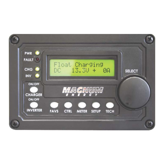
SETUP menu. This display automatically powers-up with the current system status on the top line and the home screen (detailing the inverter’s DC voltage and current as shown in Figure 5-1) on the bottom line. © 2012 Magnum Energy, Inc. -
Page 56: On/Off Pushbuttons
CAUTION: An accessory that is networked to the inverter may have adjustable settings that revert back to default if all power to the inverter is lost. Refer to the owner’s manual for the particular accessory to determine if any setting is affected. © 2012 Magnum Energy, Inc. -
Page 57: Operating The Inverter/Charger
WARNING: Do not perform an Equalization charge without read- ing and following all safety precautions pertaining to charging/ equalization as noted in this manual and provided by the battery manufacturer, and any equalization information in the inverter owner’s manual. © 2012 Magnum Energy, Inc. -
Page 58: System Status Messages
The Search mode function is used to reduce the inverter draw from the battery, and may be turned off at any time if you want full inverter output voltage available at all times (see 02 Invert Setup on page 23). © 2012 Magnum Energy, Inc. -
Page 59: Charger Mode Messages
The Equalize charge will continue for four hours and then automatically stop and return to Float charging. The Equalize charge can be manually stopped by pressing and holding down the ON/OFF CHARGER button (about fi ve seconds) until the LCD screen displays “Float Charging”. © 2012 Magnum Energy, Inc. - Page 60 Most batteries require a Bulk and Absorption charge cycle in order to fully recombine the electrolyte in the batteries and bring the specifi c gravity to the proper level. Be sure to check with your battery manufacturer before using this setting. © 2012 Magnum Energy, Inc.
- Page 61 Set DC Volts to ReBulk setting (from 03G Final Charge Stage menu) the charger will restart a Bulk and Absorb charge cycle, and then transition back into Silent mode at the end of the Absorb cycle. © 2012 Magnum Energy, Inc.
-
Page 62: Secondary Scrolling Status Messages
If the overload condition lasts for <10 seconds, the fault will automatically clear and the unit restarts and resumes operation. However, if the overload occurs for more than 10 seconds, the unit will shut down and the fault will require a manual restart. © 2012 Magnum Energy, Inc. - Page 63 Normally, the HBCO value for the ME/MM/RD Series’ inverters is 16 VDC (12-volt models) or 32 VDC (24-volt models); and, the HBCO value for the MS/MMS Series’ inverters is 17 VDC (12-volt models), 34 VDC (24-volt models), or 68 VDC (48-volt models). © 2012 Magnum Energy, Inc.
- Page 64 AC output, or the output wires are incorrectly wired. Once the AC loads are reduced or the output wiring is corrected, manu- ally restart the inverter to resume operation. If this fault condition continues perform a inverter reset. © 2012 Magnum Energy, Inc.
-
Page 65: Stacking Fault Messages
(listen and make sure you hear an audible “click” from the connectors at both inverters). Info: This fault has been known to occur when a Magnum Energy accessory is plugged into the Stack Port, but the installation is not using multiple inverters in a stacked confi... -
Page 66: Internal Fault Messages
ON/OFF INVERTER pushbutton on the remote to turn the inverter on and verify the fault has cleared (i.e. manual restart). If the internal fault remains or returns, the inverter will require repair at an Magnum Energy Authorized Service Center, for locations see http://www.magnumenergy.com/Service/ServiceCenters-US.htm. •... -
Page 67: Led Indicator Guide
INV and CHG LEDs are on); the inverter will (green) automatically supply AC power to the loads if utility or generator power is lost. Inverter is in Search mode (the AC load is below BLINKING the SETUP menu’s 02A Search Watts setting). © 2012 Magnum Energy, Inc. -
Page 68: Troubleshooting
Inverter is not Ensure inverter batteries are connected to connected and the inverter batteries. is operating correctly without any AC power connected (can invert and power AC loads from batteries). © 2012 Magnum Energy, Inc. -
Page 69: Troubleshooting Tips
Battery Temperature Sensor (BTS) temperature. If the BTS is installed, the charge voltage settings will increase if the temperature around the BTS is below 77° F (25° C), and decrease if the temperature around the BTS is higher than 77° F (25° C). © 2012 Magnum Energy, Inc. -
Page 70: Performing An Inverter Reset
Info: If DC disconnects are not used, there may be a momentary spark when the positive battery cable is connected to the inverter’s terminal. This is normal and indicates that the inverter’s internal capacitors are being charged. © 2012 Magnum Energy, Inc. -
Page 71: Using A Me-Ags-N Module
SOC² is higher Starts when tempera- Stops after a set time 04E Gen Run ture increases period Temp Note¹: Only applicable to MS-PAE, MS-PE and MSH inverters. Note²: Autostart/stop conditions using SOC require the ME-BMK. © 2012 Magnum Energy, Inc. - Page 72 If you are unsure what loads might be running or where to set the start delay, error on setting a shorter time such as the default of two minutes (to protect batteries from over-discharge). © 2012 Magnum Energy, Inc.
- Page 73 Charge mode. Once the inverter/charger enters Float Charge mode, the AGS will autostop the generator. Note¹: When the inverter’s Battery Temperature Sensor (BTS) is connected, the actual absorb charge voltage will increase or decrease to ensure correct charging as the battery temperature changes. © 2012 Magnum Energy, Inc.
- Page 74 Why use Gen Run Amps? This setting is useful when there is a large load or a combination of loads that the inverter can run, but doing so quickly de- pletes the battery bank (motors, well pumps, A/C units, freezer, etc.). © 2012 Magnum Energy, Inc.
- Page 75 METER button’s 04A BMK SOC display. This is considered the best overall method for using AGS settings to start and stop your generator. Note¹ – For a 4000 watt inverter, set Start Gen AC Amps at 25A. © 2012 Magnum Energy, Inc.
- Page 76 Default setting: Set Gen Run Temp Start = OFF Range: OFF, Ext Input, 65-95F or 18-35C © 2012 Magnum Energy, Inc.
- Page 77 Run Temp Time setting or the SETUP: 04F Max Gen Run Time setting is reached, whichever occurs fi rst. This means you could set the time to the lowest time setting (0.5 Hrs), knowing the generator will attempt to run until the temperature setting is met. © 2012 Magnum Energy, Inc.
- Page 78 SETUP: 04G Quiet Time Menu feature. • Set Quiet Time – Set to On (allows you to set the start and stop times). Default setting: Set Quiet Time = OFF Range: OFF, ON, [daily start and stop time settings (12:00AM-12:00PM)] © 2012 Magnum Energy, Inc.
- Page 79 SOC (State of Charge) parameters requires the optional Battery Monitor Kit (ME-BMK or ME-BMK-NS) to be installed and enabled. Note²: This voltage is scaled depending on your battery system; ≤0.3 for 12-volt systems, ≤0.6 for 24-volt systems, and ≤1.2 for 48-volt systems. © 2012 Magnum Energy, Inc.
- Page 80 This applies to both gas and diesel generators. When generators sit unused for as little as 30 days moisture can build up, and may damage your generator. Also, the fuel in gasoline-powered generators can © 2012 Magnum Energy, Inc.
- Page 81 On Day 5 at 8:30AM (Days Since Run timer displays “3 days”), the second required condition is met and the generator automatically starts and runs for one hour (Set Gen Exercise Run Time = 1.0 Hrs). © 2012 Magnum Energy, Inc.
-
Page 82: Me-Ags-N Functional Tests
AGS. If the AGS status displayed is not Off or Ready, then refer to Section 7.8.2 “Resolving Operational Statuses” or Section 7.8.3 “ME-AGS-N Faults using your Remote” for assistance before continuing. © 2012 Magnum Energy, Inc. -
Page 83: Starting The Generator From The Remote
OFF position for safety. Info: If the generator is manually started from the generator con- trol panel or a generator remote panel, selecting OFF may not shut down the generator. © 2012 Magnum Energy, Inc. -
Page 84: Monitoring The Ags
Info: This menu is important when determining if the AGS is work- ing correctly, or for troubleshooting an AGS installation. For any fault mode displayed in the status menu, refer to Section 7.7.3 in this manual. © 2012 Magnum Energy, Inc. - Page 85 Info: When the DIP switch inside the AGS is set to “2-Wire Standby Mode”, if you do not use the ME-ARC to manually turn the generator on, the Days Since Run timer will not be reset to zero. © 2012 Magnum Energy, Inc.
-
Page 86: Me-Arc Remote's Ags Tech Button
Figure 7-1, AGS Fault History Menu Items • 04C Clear Faults – This menu allows all recorded fault history infor- mation—for any inverter and/or AGS that is network connected—to be cleared/erased. © 2012 Magnum Energy, Inc. -
Page 87: Enabling The Me-Ags-N
Press the SELECT knob again to select this setting. The selection arrow appears to the right of the screen. The generator should start at this time. If the generator does not start as expected, refer to Section 7.8 “ME-AGS-N Remote Troubleshooting” in this manual. © 2012 Magnum Energy, Inc. - Page 88 If the SETUP: 04A Gen Run VDC is set to OFF, the Start/Stop Volts Delay and Stop Gen Volts values that were entered prior to selecting OFF will still be used to autostop the generator. © 2012 Magnum Energy, Inc.
-
Page 89: Me-Ags-N Menu Map Using The Me-Arc
Set Stop Gen Minute = 00:00 Minute = 00:59 Set Stop Gen Set Stop Gen AM-PM 00:00 AM-PM 00:00 SETUP Menu continues on next page Figure 7-2, ME-AGS-N Menu Maps using ARC Remote (Section 1) © 2012 Magnum Energy, Inc. -
Page 90: Figure 7-3, Me-Ags-N Menu Maps Using Arc Remote (Section 2)
00:00 Set Quiet Time Set Quiet Time Set Quiet Time Topoff = 30Min Topoff = 120Min Topoff = OFF SETUP Menu continues on next page Figure 7-3, ME-AGS-N Menu Maps using ARC Remote (Section 2) © 2012 Magnum Energy, Inc. -
Page 91: Figure 7-4, Me-Ags-N Menu Maps Using Arc Remote (Section 3)
Menu Selections Set Gen Exercise Default/Current Days = OFF Setting Notes: = current setting** ** For this menu map, the arrow denotes the factory default settings Figure 7-4, ME-AGS-N Menu Maps using ARC Remote (Section 3) © 2012 Magnum Energy, Inc. -
Page 92: Me-Ags-N Remote Status Messages
If an AGS is installed, then refer to Section 7.8.2 “Re- solving Operational Statuses” for assistance. The CTRL: 03 Gen Control menu is set to OFF. This set- ting will not allow the AGS to autostart the generator. © 2012 Magnum Energy, Inc. -
Page 93: Ags Remote Start Statuses
The generator has started based on the SETUP: 04B Gen Run Time setting. Start Topoff The generator has started based on the SETUP: 04G Quiet Time Topoff Time setting. Start VDC The generator has started based on SETUP: 04A Gen Run VDC setting. © 2012 Magnum Energy, Inc. -
Page 94: Ags Remote Fault Statuses
Gen Run Amps* Gen Run SOC Gen Run Temp Max Gen Run Time 12.0 Hrs Quiet Time Gen Exercise Gen Warm-up Time 60 Sec Gen Cooldown Time 60 Sec *MS-PAE, MS-PE and MSH Series models only © 2012 Magnum Energy, Inc. -
Page 95: Ags Notes
(e.g., Start Gen AC Amps) is satisfi ed by its autostop condition (e.g., Stop Gen AC Amps). Once the generator has completed this autostart/ autostop cycle, the AGS immediately begins to monitor for any active autostart/autostop settings again. © 2012 Magnum Energy, Inc. -
Page 96: Me-Ags-N Remote Troubleshooting
(blinking or solid) to indicate that the AGS module is getting power. Ensure the communications cable is connected from the Net- work port on the Magnum inverter to the NETWORK port on the ME-AGS-N. Ensure you have the correct communications cable. © 2012 Magnum Energy, Inc. -
Page 97: Resolving Ags Faults Using The Remote
B. The generator started, but did not provide the correct gen run sense signal to the AGS module. For either scenario, refer to your ME-AGS-N owner’s manual. © 2012 Magnum Energy, Inc. - Page 98 Absorb Charge stage. Ensure the SETUP: 03E Absorb Done (Time, Amps, or SOC) setting—determines when the Absorb Charge stage is complete and enters the Float stage—is taken into account when setting the 04F Max Gen Run Time setting. © 2012 Magnum Energy, Inc.
-
Page 99: How To Clear Ags Faults
“5.0 to 0.0 second” screen countdown is fi nished and the screen displays “HISTORY CLEARED”. Info: Be sure you do not want the fault history for either device (inverter or AGS). Once it has been cleared, it cannot be re- trieved. © 2012 Magnum Energy, Inc. -
Page 100: Using A Me-Bmk
How do I access the charge effi ciency setting? Press the ARC’s SETUP button, rotate the SELECT knob to the 05 BMK Setup menu, and then press the SELECT knob again to access the 05A Charge Eff menu item (see Figure 8-1). © 2012 Magnum Energy, Inc. -
Page 101: Monitoring The Bmk
SELECT knob to adjust the AH size setting. Press the SELECT knob to select and save the new setting. 8.2 Monitoring the BMK Use the ARC remote’s METER button to monitor battery bank information and to determine the status of your battery system. © 2012 Magnum Energy, Inc. - Page 102 When this value is positive, it represents amp-hours returned to the battery during any subsequent charging. A negative value represents amp-hours removed from a full battery. The range is ±32,768 AH. © 2012 Magnum Energy, Inc.
-
Page 103: Table 8-1, Bmk Default Settings On Me-Arc
DC input values. If the battery monitor is not connected or not communicating, the display shows “0.0”. Table 8-1, BMK Default Settings on ME-ARC Menu Items Default Settings Charge Eff Auto AmpHour Size 400 AH © 2012 Magnum Energy, Inc. -
Page 104: Me-Arc Remote's Bmk Menu Maps
(press and hold the SELECT knob for 5 seconds to reset values) = Current setting** ** - For this menu map, the arrow denotes the factory default settings Figure 8-1, ME-BMK Menu Maps using ARC Remote © 2012 Magnum Energy, Inc. -
Page 105: Limited Warranty
9.0 Service and Warranty Info 9.0 Limited Warranty Magnum Energy, Inc., warrants the ME-ARC remote control to be free from defects in material and workmanship that result in product failure during normal usage, according to the following terms and conditions: The limited warranty for this product extends for a maximum of 12 months from the product’s original date of purchase. -
Page 106: How To Receive Repair Service
Telephone: 425-353-8833 Fax: 425-353-8390 Email: warranty@magnumenergy.com If returning your product directly to Magnum Energy for repair, you must: • return the unit in the original, or equivalent, shipping container • receive a Return Materials Authorization (RMA) number from the factory prior to the return of the product to Magnum Energy for repair. - Page 107 Magnum Energy, Inc. 2211 West Casino Rd. Everett, WA 98204 Phone: 425-353-8833 Fax: 425-353-8390 Web: www.magnumenergy.com PN: 64-0030 Rev B...
Need help?
Do you have a question about the ME-ARC Series and is the answer not in the manual?
Questions and answers