
Subscribe to Our Youtube Channel
Related Manuals for Magnum Energy ME-ARC


Summary of Contents for Magnum Energy ME-ARC
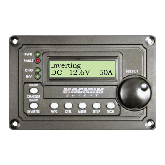
- Page 1 ME-ARC Remote Control Inverting DC 12.6V Owner’s Manual (for Revision 2.1 or higher)
- Page 2 Restrictions on Use The ME-ARC remote shall not be used in connection with life support systems, life saving or other medical equipment or devices. Using the ME-ARC with this particular equipment is at your own risk.
-
Page 3: Table Of Contents
6.0 Troubleshooting ..............55 6.1 Troubleshooting Tips..............56 6.1.1 Inverter Problems ............... 56 6.1.2 Charger Problems ............... 56 6.2 Performing an Inverter Reset ............ 57 6.3 Powering Down the Inverter ............. 57 7.0 Limited Warranty ..............58 © 2010 Magnum Energy, Inc. - Page 4 Figure 3-7, TECH Button ..............30 Figure 4-1, Inverter/Charger Menu Map (Pages 1 - 4) ...... 34-37 Figure 5-1, ME-ARC Front Panel Controls and Indicators......38 Figure 5-2 to 5-5, Inverter Modes ..........41-42 Figure 5-6 to 5-15, Charging Modes ..........42-46 Figure 5-16, Low Battery Fault ............
-
Page 5: Overview
Info: This manual is for the ME-ARC with revision 2.1 or higher; see the TECH: 02 Revisions display on page 16 for information on how to determine your revision level. -
Page 6: Installation
2.0 Installation Before installing the remote, read the entire installation section to determine how you are going to install your ME-ARC. The more thorough you plan in the beginning, the better your inverter needs will be met. Info: Installations should be performed by qualifi ed personnel, such as a licensed or certifi... -
Page 7: Bezel Mount Installation Procedure
AC power is connected to the inverter. 5 7 /8 in [148.6 mm] 5 1/4 in [133.35 mm] 4 3/8 in [110.5 mm] 4 3/8 in [110.5 mm] Figure 2-2, Remote Bezel Dimensions © 2010 Magnum Energy, Inc. -
Page 8: Power-Up Routine
2.5 Power-up Routine • Power up Routine: When the ME-ARC is first connected to the inverter a power up routine is initialized. During the power up routine the LCD will read: Magnum Energy, Self Test, (C) 2009, Connecting to..., ME-ARC V #.#, INV/CHG V #.#. -
Page 9: Setup
3.1 Navigating the Remote’s Menu The ME-ARC has an internal structure that provides menu items and adjust- able settings that provide the ability to confi gure your inverter/charger to your specifi... -
Page 10: Figure 3-2, Setup Menu Navigation
Rotate the SELECT knob to the desired setting. When the bottom line shows the Set Search Watts 5 Watts desired setting - 5. Press the SELECT knob to “save” this desired setting. Figure 3-2, SETUP Menu Navigation © 2010 Magnum Energy, Inc. -
Page 11: Pushbuttons And Menu Items
Menu heading. Menu items are identifi ed by a number followed by a letter. Status Example: “02 Invert Setup” is a menu heading 02 Invert Setup 02A Search Watts Example: “02A Search Watts” is a menu item 5 Watts © 2010 Magnum Energy, Inc. -
Page 12: Figure 3-3, Favs Button
24 for SETUP 03B Battery Type on how to set the Battery Type. FAVS: F5 Gen Control - Gen Control is the F5 default (FAVS #5). Refer to page 11 for CTRL 03 Gen Control on how to operate the Gen Control func- tion. © 2010 Magnum Energy, Inc. -
Page 13: Ctrl (Control) Button
AC. Once this time is set in the setup menu use the CTRL button to access the “ACIn Control” menu and select “Time Connect”. When “Time Connect” is selected the inverter/charger will only connect to AC when the time is between 12AM and 8AM. © 2010 Magnum Energy, Inc. -
Page 14: Acin Control
Float or Rebulk, using Force Float or Restart Bulk from the CTRL button 02 CHG Control menu. Info: Multi-Stage must be selected in order for the Final Charge Stage selected in menu 03G Final Charge Stage to be used. © 2010 Magnum Energy, Inc. -
Page 15: Gen Control
When the OFF position is selected the generator will not start automatically. Info: If DC power is lost to the remote, this menu resets to the default OFF position for safety. © 2010 Magnum Energy, Inc. -
Page 16: Figure 3-5, Meter Button
Bottom line show s current desired m enu heading Press to selection : select m eters Status Status Status Status 01 DC Meters 02 AC Meters 03 AGS Meters 04 BMK Meters Figure 3-5, Meter Button © 2010 Magnum Energy, Inc. -
Page 17: Meter Button
Float, Charger Standby, Full or Silent mode. Info: Once the charger leaves the absorption mode and enters the “Final Charge Stage”, this timer is reset and will not accumulate until the charger reenters the Bulk or Absorption charge mode. © 2010 Magnum Energy, Inc. -
Page 18: Ac Meters
Gen Warm-up: The generator has successfully started on one of the start settings, but has not connected to the inverter/charger because it is wait- ing to satisfy the warm-up time set in menu “04I Gen Warm-up Time”. © 2010 Magnum Energy, Inc. - Page 19 “03 Gen Control” menu or from a start/stop switch directly connected to the generator. • No Comm: The ME-AGS-N is not communicating with the ME-ARC re- mote. Causes could be a bad ME-AGS-N network cable, no power to the ME-AGS-N, or there is no ME-AGS-N installed in the system.
-
Page 20: Bmk Meters
BMK is in. BMK Ready: This indicates there is an optional ME-BMK installed in the system, and that it is powered and communicating with the ME-ARC. Power-up Fault: This indicates the ME-BMK has failed to properly power-up during normal installation procedures. Refer to the ME-BMK manual for troubleshooting information. - Page 21 (battery charger, charge controller, etc.), to ensure the charging voltage has been attained. This display is also helpful when troubleshooting or detecting if an over- charge condition has occurred. © 2010 Magnum Energy, Inc.
-
Page 22: Setup Button
CTRL menu. Pressing the SETUP menu button provides access to the menu items and set- tings that allow the ME-ARC display, inverter/charger, ME-AGS-N and ME-BMK to be confi gured. Read each menu item to determine if any setting requires adjustment to meet your system requirements. -
Page 23: Remote Setup
• 01A Set Clock: The ME-ARC contains a real time clock that must be set for proper operation of some features. These features are: 02C AC In-Time, 04B Gen Run Time, 04G Quiet Time, 04H Gen Exercise and 04 Fault History under the TECH button. -
Page 24: Invert Setup
17.0 volts (24-volt models), or 34.0 (48-volt models); the fault LED and ‘Low Battery’ status will be immediate. Default settings: LBCO = 10.0 VDC (12-volt models), 20.0 VDC (24-volt models) or 40.0 VDC (48-volt models). © 2010 Magnum Energy, Inc. - Page 25 02C AC In-Time menu. Even if AC is present on the AC input terminals of the inverter/charger it will only connect during those times that were previously set up. © 2010 Magnum Energy, Inc.
- Page 26 12.2 VDC and charge the batteries. You would set the disconnect voltage at the Absorb voltage for your batteries to make sure the batteries received at least a 75-80% charge before the AC is disconnected. © 2010 Magnum Energy, Inc.
-
Page 27: Charger Setup
If MS-AE or MS-PAE models are used, these models have HOT IN 1 and HOT IN 2 and the current on both inputs are monitored. Set the AC Input Amps to match the input breaker size on these models. © 2010 Magnum Energy, Inc. -
Page 28: Table 3-3, Battery Type To Charge Voltages
= 0% setting is available to help minimize charging while continuing to allow pass-thru power. The rest of the selections are provided to limit the charge rate to the battery bank, which helps prevent battery overheating caused by charging at too high a charge rate. © 2010 Magnum Energy, Inc. - Page 29 If this setting is set to Dropout = 60 VAC, when the AC input voltage drops to 60 volts, the inverter will switch from charge mode to inverter mode. Default setting: Dropout 80 VAC (Export inverter models 160 VAC) © 2010 Magnum Energy, Inc.
- Page 30 Absorb time may be needed in order to obtain the appropriate Absorb time for your battery type and bat- tery bank size. Default Setting: Absorb Done Time = 2.0 Hrs © 2010 Magnum Energy, Inc.
- Page 31 If a lower setting than 100% is used, then at least once a week the batteries should be charged to 100%, to make sure damage is not done to the batteries by not bringing them to a full charge state. © 2010 Magnum Energy, Inc.
- Page 32 fl oat mode for another 4 hour period. The “Full Charge” feature in the Multi mode also helps reduce water consumption in fl ooded batteries when left in the charge mode for extended periods, such as in a backup power application. © 2010 Magnum Energy, Inc.
-
Page 33: Ags Setup
• Gen Run Time - starts and stops the generator based on time of day. This feature uses the ME-ARC clock to determine start and stop times. • Gen Run Amps - starts and stops the generator based the AC amp load on the inverter in Invert mode. -
Page 34: Bmk Setup
T EC H m enu 01 Temperatures 04 Fault History 05 SETUP PIN 06 Ext Control 07 Load Defaults … .. Press Select Press Select SETUP Unlocked Press Select Press Select Figure 3-7, TECH Button © 2010 Magnum Energy, Inc. - Page 35 If the ME-ARC is connected to a Router (ME-RTR), the Router revi- sion will be displayed, but not all functions of the ME-ARC will be available. The ME-ARC has limited functions as a second remote connected to the Router.
- Page 36 PIN. In menu 05 SETUP PIN when “PIN = 0***” is displayed, press and hold the Select knob until “PIN = 0000” is displayed. Enter a new PIN number as described in 05 SETUP PIN above. © 2010 Magnum Energy, Inc.
- Page 37 Info: There are some SETUP menus that may be desirable to ac- cess without giving access to the PIN number to users. This is made possible in ME-ARC with the FAVS button. Before setting the PIN number, enter the desired SETUP menus in the FAVS button. Once the SETUP menus have been entered in the FAVS button the PIN number can now be entered and the SETUP button will be locked.
-
Page 38: Menu Map: Section 1-4
4.0 Menu Map 4.0 Menu Map: ME-ARC Remote Control Figure 4-1 (four pages) is a complete overview of the remote and inverter/ charger settings and info displays available in the ME-ARC; this should help with menu navigation. FAVS F1 Search Watts... - Page 39 4.0 Menu Map 4.0 Menu Map: ME-ARC Remote Control (continued) continued… . SETU P Status 01 Remote Setup 01A Set Clock R an g e : 12 : 00 A M – 12 : 00 PM 11:18AM Set Clock...
- Page 40 4.0 Menu Map 4.0 Menu Map: ME-ARC Remote Control (continued) continued… . SETU P Status 03 Charger Setup 03A AC Input R an g e : 5 A t o 60 A Amps = 30A Set AC Input Set AC Input...
- Page 41 4.0 Menu Map 4.0 Menu Map: ME-ARC Remote Control (continued) continued… . SETU P Status 04 AGS Setup R efer to the M E-A GS Ow ner’s M anual (part num ber: 64-0005) for detailed inform ation on this m enu.
-
Page 42: Operation
LCD display. 5.1 Front Panel The ME-ARC front panel contains LEDs and a LCD display for viewing system status; pushbuttons to control system operation; and a rotary knob that allows an easy way to select and fi nd system information. -
Page 43: On/Off Pushbuttons
BMK settings. Push or “SELECT” the rotary knob to enter a menu item or to “save” a setting once it is displayed on the LCD screen. Info: All adjustable inverter/charger settings in the ME-ARC (except for 01B Contrast, 01C Backlight and 03 AGS Control - which revert... -
Page 44: Operating The Inverter/Charger
To enable the Equalization charge; see Figure 5-11 and follow all related information on page 46. © 2010 Magnum Energy, Inc. -
Page 45: System Status Messages
FAULT are on solid. The FAULT (red) and Settings/Info... CHG LED’s are off. Figure 5-4, Inverting Mode • Inverting - The inverter is providing AC voltage on its output by Inverting power from the batteries. © 2010 Magnum Energy, Inc. -
Page 46: Charger Mode Messages
Figure 5-5, No Inverter Communication Mode • No Inverter Comm - The ME-ARC is not communicating with the inverter/charger. The ME-ARC uses a standard telephony wired cable and is receiving power and ground from the inverter/charger to power up, but the transmit and receive wires are not working. - Page 47 Table 3-3, Battery Type to Charge Voltages. Info: If the battery voltage falls ≤12.1 VDC (12-volt models), ≤24.2 VDC (24-volt models) or ≤48.4 VDC (48-volt models); the unit will initiate bulk charging. © 2010 Magnum Energy, Inc.
- Page 48 “Set DC Volts to ReBulk” setting in menu 03G Final Charge Stage the charger will restart a Bulk and Absorb charge cycle, and then transition back into the Silent mode at the end of the Absorb cycle. © 2010 Magnum Energy, Inc.
- Page 49 Most batteries require a Bulk and Absorption charge cycle in order to fully recombine the electrolyte in the batteries and bring the specifi c gravity to the proper level. Be sure to check with your battery manufacturer before using this setting. © 2010 Magnum Energy, Inc.
- Page 50 If in doubt, disconnect the DC loads to prevent damage. Info: Equalization charging is not available if GEL or AGM 2 is selected under Setup 03B Battery Type menu. © 2010 Magnum Energy, Inc.
-
Page 51: Fault Mode Messages
34 VDC (24-volt models), or 68 VDC (48-volt models). Remedy: This fault usually only occurs when an external DC charg- ing source is charging the inverter’s battery bank. Turn off any other additional charging source to allow the DC voltage level to drop. © 2010 Magnum Energy, Inc. -
Page 52: Figure 5-18, Overtemp Fault
AC input. Remedy: Remove all AC power from the inverter’s AC input for at least 15 minutes to automatically restart this fault; ensure only 120VAC power is connected to each of the inverter’s AC inputs. © 2010 Magnum Energy, Inc. -
Page 53: Figure 5-22, Dead Battery Charge Fault
AC output, or the wires are incorrectly wired. Once the AC loads are reduced or the output wiring is corrected; manually restart the inverter to resume operation. If this fault condition continues after all of these recommendations, perform a inverter reset (see section 6.2). © 2010 Magnum Energy, Inc. -
Page 54: Figure 5-24, Fet Overload Fault
Unknown Fault - This fault message displays when the inverter/charger has sent a fault code that cannot be determined by the remote. Remedy: Call the Technical Support department at Magnum Energy for assistance to help determine and understand the actual fault status. -
Page 55: Figure 5-27, Tfmr Overtemp Fault
Magnum Network. Remedy: Reset the remote by disconnecting the remote commu- nications cable from the inverter for 5 seconds and then reconnect (see Figure 2-3). If the fault continues, check/replace the remote cable. © 2010 Magnum Energy, Inc. -
Page 56: Stacking Fault Messages
(listen and make sure you hear an audible “click” from the connectors at both Inverters). Info: This fault has been known to occur when a Magnum Energy accessory is plugged into the Stack Port, but the installation is not using multiple Inverters in a stacked confi... -
Page 57: Internal Fault Messages
PWR (green), CHG (green) and INV Settings/Info... (green) LED’s are off. Figure 5-36, Internal Relay Fault • Internal Relay - This fault message displays and the inverter shuts down because the internal AC transfer relay protection circuit has been activated. © 2010 Magnum Energy, Inc. -
Page 58: Led Indicator Guide
CHG LED’s are on); the inverter will (green) automatically supply AC power to the loads if utility or generator power is lost. Inverter is in Search mode (the AC load is below BLINKING the Setup 02A Search Watts setting). © 2010 Magnum Energy, Inc. -
Page 59: Troubleshooting
Inverter is not Ensure inverter batteries are connected to connected and inverter is batteries. operating correctly without any AC power connected (can Invert and power AC loads from batteries). © 2010 Magnum Energy, Inc. -
Page 60: Troubleshooting Tips
• Charger says “Float Charging” not “Bulk Charging” when the AC is fi rst plugged in: Check DC voltmeter on the ME-ARC display, if the battery is over 13.0 VDC (26.0 VDC for 24-volt models or 52.0 VDC for 48-volt models) then the battery was already charged and the charger automatically goes to “Float Charging”... -
Page 61: Performing An Inverter Reset
Info: The Power ON/OFF button is a small momentary type switch which operates by lightly pressing and releasing. Info: All adjustable inverter/charger settings in the ME-ARC (except for the Setup 01B Contrast, 01C Backlight and 03 Gen Control - which... -
Page 62: Limited Warranty
7.0 Service and Warranty Info 7.0 Limited Warranty Magnum Energy, Inc., warrants the ME-ARC remote control to be free from defects in material and workmanship that result in product failure during normal usage, according to the following terms and conditions: 1. - Page 63 Magnum Energy, Inc. 2211 West Casino Rd. Everett, WA 98204 Phone: 425-353-8833 Fax: 425-353-8390 Web: www.magnumenergy.com PN: 64-0030 Rev A (02/10)
Need help?
Do you have a question about the ME-ARC and is the answer not in the manual?
Questions and answers