Table of Contents
Advertisement
Advertisement
Table of Contents
Troubleshooting

Related Manuals for Magnum Energy ME-MR


Summary of Contents for Magnum Energy ME-MR
- Page 1 ME-MR Remote Control Owner’s Manual (for Revision 1.1 or higher)
- Page 2 If the ME-MR fails, it is reasonable to assume that the health of the user or other persons may be endangered.
- Page 3 Magnum inverters. As long as AC power is connected, it will pass thru the inverter regard- less of the power switch on the inverter or the ON/OFF button on the remote. ©2013 Magnum Energy, Inc.
-
Page 4: Table Of Contents
3.2.9 Equalize Menu ..............14 3.2.10 Charger Standby Menu .............15 3.2.11 Power On Menu ...............15 3.2.12 TECH Menu ..............16 Menu Map: ME-MR Remote Control ......18 Operation ..............19 Front Panel .................19 5.1.1 LED Indicators ..............19 5.1.2 LCD Display ..............19 5.1.3 ME-MR Remote Buttons ............19... - Page 5 Figure 3-12, Power On Selections ............16 Figure 3-13, TECH Menus ..............17 Figure 4-1, ME-MR Remote Menu Map ..........18 Figure 5-1, ME-MR Front Panel Controls and Indicators ......19 Figure 5-2, Inverter Standby Mode ............ 21 Figure 5-3, Inverting Mode ............... 21 Figure 5-4, Off Mode ................
- Page 6 Table 3-2, Battery Size to Battery Amp-Hours (estimated) ...... 9 Table 3-3, Battery Type to Charge Voltages ......... 10 Table 3-4, ME-MR’s Inverter/Charger Default Settings ......17 Table 5-1, LED Indicator Guide ............35 Table 6-1, Remote Troubleshooting ............ 36...
-
Page 7: Introduction
1.0 Introduction Introduction The ME-MR remote control allows you to monitor and customize the basic operating parameters of your Magnum inverter/charger. This remote can be used on all Magnum inverter/charger models. Info: The ME-MR remote control has minimal settings available from its menu. -
Page 8: 2.0 Installation
Pre-Installation Before proceeding, read the entire Installation section to determine how best to install your ME-MR remote. The more thorough you plan in the beginning, the better your inverter needs will be met. 2.1.1 Installation Guidelines •... -
Page 9: Flush Mounting The Remote
(not supplied) as a template to mark the mounting holes. Mark and ⅛ pre-drill four ” holes (see Figure 2-2). Mount the bezel using the four #6 ¾ ” screws. Bezel front view Bezel side view (2.86 cm) Figure 2-2, Bezel Dimensions for Surface Mounted Remote ©2013 Magnum Energy, Inc. -
Page 10: Connecting The Remote
Next, mount the remote to the desired surface or to the bezel (using ½ the two supplied #6 x ” Phillips fl at head screws). The remote is ready for setup. RJ11 Connection Magnum Inverter Remote Cable Remote Port (blue) Figure 2-3, Remote Control Connections ©2013 Magnum Energy, Inc. -
Page 11: 3.0 Setup
Navigating the Remote The ME-MR has menu items and adjustable settings that provide the ability to confi gure your inverter/charger to your specifi c parameters. Info: See Figure 4-1 for a complete map of the remote’s menu items and adjustable settings. -
Page 12: Remote Menu Items
AC source is tripping (because it is a weak breaker), try reducing this setting to the next lower level. Note: If the ME-MR is connected to a MSH-RE inverter, the AC IN setting applies to both inputs (AC1 and AC2). -
Page 13: Search Watts Menu
SEARCH SAVE ON/OFF 5 Watt HOME HOLD CHANGE If this setting is correct, press MENU button to access different menu items press press press SEARCH SEARCH SEARCH 5 Watt 20 Watt Figure 3-3, Search Watts Selections ©2013 Magnum Energy, Inc. -
Page 14: Battery Amp-Hours Menu
If you are not sure of your battery’s 20 hour AH rating, consult your battery manufacturer/dealer or use Table 3-2 to obtain an estimate. ©2013 Magnum Energy, Inc. -
Page 15: Table 3-2, Battery Size To Battery Amp-Hours (Estimated)
“series string” and the amp-hour capacity doesn’t change. Each series string is connected together in parallel to increase the amp-hour capacity. Add the amp-hour capacity of each series string connected in parallel to determine the total amp-hour capacity of the battery bank. ©2013 Magnum Energy, Inc. -
Page 16: Battery Type Menu
CHANGE HOLD If this setting is correct, press MENU button to access different menu items press press press BAT TYPE BAT TYPE BAT TYPE BAT TYPE Flooded AGM 1 AGM 2 Figure 3-5, Battery Type Selections ©2013 Magnum Energy, Inc. -
Page 17: Charge Rate Menu
(i.e., 400 AH ÷ 5 = 80 amp maximum charge rate). A lower rate such as C/20* is used when the batteries need to be charged as slow as possible. The ME-MR provides three settings for charge rate adjustment—10, 50, and 100%. Multiply this percentage and the max charge rate of the inverter to fi... -
Page 18: Low Battery Cut-Out (Lbco) Menu
If this setting is correct, press MENU button to access different menu items press press press LBCO LBCO LBCO 9 VDC 10 VDC 11 VDC Note: Values shown are for a 12-volt inverter Figure 3-7, LBCO: Low Battery Cut-Out Selections ©2013 Magnum Energy, Inc. -
Page 19: Vac Dropout Menu
fl uctuations in RMS voltage. These settings are highly recommended if using a generator for charging. Note: If the ME-MR is connected to a MSH-RE inverter, the VAC Dropout setting applies to both inputs (AC1 and AC2). -
Page 20: Equalize Menu
To start current “saved” setting equalization: MENU EQUALIZE ON/OFF Disabled HOME CHANGE If this setting is correct, press MENU button to access different menu items press press EQUALIZE EQUALIZE EQUALIZE Disabled Request EQing Figure 3-10, Equalize Selections ©2013 Magnum Energy, Inc. -
Page 21: 3.2.10 Charger Standby Menu
Why use the Power On feature? Some customers are familiar with Uninterruptible Power Supplies (UPS) that power-up automatically when DC power is connected. The Power On feature can be used by customers that want to obtain the same automatic power-up feature with which they are familiar. ©2013 Magnum Energy, Inc. -
Page 22: 3.2.12 Tech Menu
SETUP: Allows you to Lock or Unlock the setup menus on your remote. Press the SAVE/HOLD button to select to lock the setup menus (Lock) or to unlock (Unlock) the setup menus. Note: Exception - AC In menu does not lock. ©2013 Magnum Energy, Inc. -
Page 23: Figure 3-13, Tech Menus
**Press the SAVE/HOLD button to select Lock or Unlock Figure 3-13, TECH Menus Defaults: This menu restores all settings on the ME-MR (and in the in- verter/charger) to the original factory default settings. To restore, press and hold the SAVE/HOLD button for 5 seconds (see Figure 4-1). After the default settings have been restored, the display will show “Loaded”. -
Page 24: Menu Map: Me-Mr Remote Control
4.0 Menu Map Menu Map: ME-MR Remote Control This menu map is an overview of the inverter/charger settings (arrows denote factory defaults) and the info displays available from the ME-MR remote. MENU HOME AC IN AC IN AC IN AC IN... -
Page 25: Operation
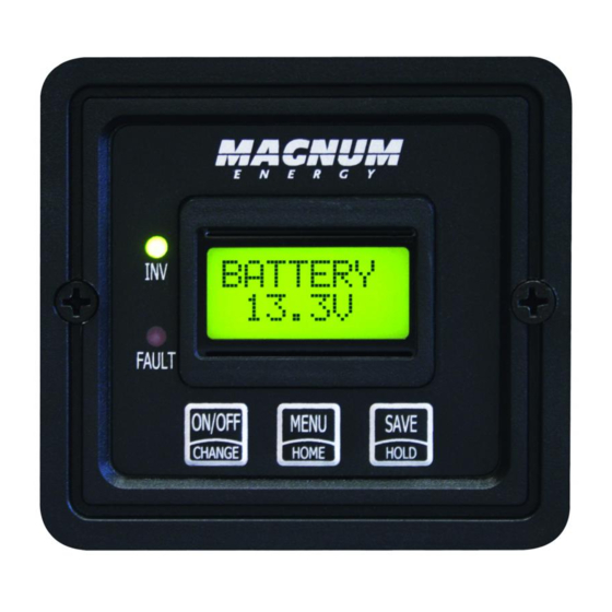
Front Panel The ME-MR front panel contains two LEDs and a LCD display for viewing system status, and three buttons to control system operation. 5.1.1... -
Page 26: Operating The Inverter/Charger
(see Section 6.2), or if all power to the remote or inverter is removed. Info: The ME-MR remote is only used to control an inverter. In order to control or display a Magnum Energy accessory, you need to use a ME-RC50 or ME-ARC50 remote control. -
Page 27: System Status Messages
(green) LED is on solid. The FAULT (red) LED is off. STATUS Invert Figure 5-3, Inverting Mode • Inverting Mode – The inverter is providing AC voltage on its output by inverting power from the batteries. ©2013 Magnum Energy, Inc. -
Page 28: Charger Mode Messages
Battery Type setting) while Bulk Charging. During this stage, the DC charging current decreases as the battery becomes charged. This Charge stage continues until the absorb charging time (determined by the Battery Amp-Hours setting) is fi nished. ©2013 Magnum Energy, Inc. -
Page 29: Figure 5-7, Bulk Charging Mode
(≤12.8 VDC/12-volt models, ≤25.6 VDC/24-volt models, or ≤51.2 VDC/48-volt models), the charger initiates Bulk Charging. If the DC voltage is higher than this voltage, the charger skips the Bulk and Absorb Charging stages and goes directly to Float Charging. ©2013 Magnum Energy, Inc. -
Page 30: Figure 5-10, Equalizing Mode
CAUTION: Ensure the DC loads will not be damaged by the higher voltage applied to the batteries during equalization. If in doubt, disconnect the DC loads to prevent damage. Info: Equalization is not available if GEL or AGM 2 is selected from the Battery Type menu. ©2013 Magnum Energy, Inc. -
Page 31: Figure 5-11, Float Charging Mode
AC source can provide on its own. The inverter pulls the additional current— needed for the loads—from the batteries to keep the incoming AC current from exceeding the AC IN setting. ©2013 Magnum Energy, Inc. -
Page 32: Figure 5-14, Load Support Vdc Mode
(green) LED could be on or off. STATUS Mode XX Figure 5-15, Unknown Mode • Unknown Mode XX – The remote doesn’t recognize the mode the inverter is reporting. Contact Magnum Technical Support (425-353-8833) for assistance. ©2013 Magnum Energy, Inc. -
Page 33: Fault Mode Messages
(or able to be connected to) the incoming AC source. When this fault happens, all system wiring should be re-checked to ensure the incoming hot and and/or neutral wires are not able to be connected to the AC output. ©2013 Magnum Energy, Inc. -
Page 34: Figure 5-18, Breaker Tripped Fault
(12-volt models), 25.2 volts (24-volt models), or 50.4 volts (48- volt models) as detected by the inverter. FetOvrld appears on the LCD and the FAULT (red) LED is on. The INV (green) LED is off. FAULT ! FetOvrld Figure 5-20, FET Overload Fault ©2013 Magnum Energy, Inc. -
Page 35: Figure 5-21, High Battery Fault
54°C/129°F. Now remove the BTS from the inverter’s BTS port. If the BTS reading goes to 25°C/77°F, replace the BTS. If the reading does not go to 25°C/77°F, then inspect the BTS port for cleanliness and/or have the inverter/charger serviced. ©2013 Magnum Energy, Inc. -
Page 36: Figure 5-23, High Volts Ac Fault
Remedy: Reset the remote by disconnecting the remote commu- nications cable from the inverter for 5 seconds, and then reconnect it (see Figure 2-3). If the fault continues, fi rst check/replace the remote cable. This cable is 4-wire telephone cable. ©2013 Magnum Energy, Inc. -
Page 37: Figure 5-26, Overcurrent Fault
If it occurs while charging, turn down the charge rate. If this fault happens often, ensure the inverter is not in a hot area, has proper ventilation, and the cooling fans inside the inverter are working. ©2013 Magnum Energy, Inc. -
Page 38: Figure 5-28, Stuck Relay Fault
• Unknown Fault – When a number appears in the second line of the remote it means the remote doesn’t know what fault the inverter is reporting. Contact Magnum Technical Support for assistance with this fault. ©2013 Magnum Energy, Inc. -
Page 39: Figure 5-31, Stack Clock Fault
(ensure you hear an au- dible “click” from the connectors at both inverters). Info: This fault may occur when a Magnum Energy accessory is plugged into the Stack port, but the installation is not using mul- tiple inverters in a stacked confi... -
Page 40: 5.3.3.3 Internal Fault Messages
FAULT (red) LED is on. The INV (green) LED is off. FAULT ! NTC Snsr Figure 5-36, Internal NTC Sensor Fault • Internal NTC Sensor Fault – The inverter shuts down because the internal NTC (temperature sensor) circuit has been activated. ©2013 Magnum Energy, Inc. -
Page 41: Led Indicator Guide
Inverter is in Search mode (the AC load is below BLINKING the Search Watts setting). Normal operation. FAULT (red) A fault condition has been detected, check the LCD display to fi nd and correct the cause. ©2013 Magnum Energy, Inc. -
Page 42: Troubleshooting
Inverter is not Ensure inverter batteries are connected to connected and the inverter is batteries. operating correctly without any AC power connected (should be able to invert and power AC loads from batteries). ©2013 Magnum Energy, Inc. -
Page 43: Troubleshooting Tips
Remote displays “Float” not “Bulk” when the AC is fi rst plugged in: Check DC volts on the ME-MR display, if the battery is over 13.0 VDC (26.0 VDC for 24-volt models or 52.0 VDC for 48-volt models) then the battery was already charged and the charger automatically goes to Float Charging to keep from overcharging the batteries. -
Page 44: Performing An Inverter Reset
Info: The Power ON/OFF pushbutton is a small momentary type switch which operates by lightly pressing and releasing. Info: All adjustable inverter/charger settings in the ME-MR are saved in non-volatile memory and are preserved until changed— even if an inverter reset is performed, or if all power to the remote or inverter is removed. -
Page 45: Warranty And Service Information
Magnum Energy shall not be liable for any other losses or damages. -
Page 46: 7.1.1 How To Receive Repair Service
If your product requires warranty service or repair, contact either: • An authorized service center, as listed at: http://www.magnumenergy.com/Service/ServiceCenters-US.htm, or • Magnum Energy, Inc. at: Telephone: 425-353-8833 Fax: 425-353-8390 Email: warranty@magnumenergy.com If returning your product directly to Magnum for repair, you must: Return the unit in the original, or equivalent, shipping container. - Page 47 Magnum Energy, Inc. 2211 West Casino Rd. Everett, WA 98204 Phone: (425) 353-8833 Fax: (425) 353-8390 Web: www.magnumenergy.com PN: 64-0031 Rev D...
Need help?
Do you have a question about the ME-MR and is the answer not in the manual?
Questions and answers