Table of Contents
Advertisement
Quick Links
Advertisement
Table of Contents

Related Manuals for Magnum Energy MM-R


Summary of Contents for Magnum Energy MM-R
-
Page 1: Remote Controls
MM-R and M-RC Remote Controls Owner’s Manual... - Page 2 © 2010 Magnum Energy, Inc.
-
Page 3: Contact Information
Restrictions on Use The MM-R and MM-RC Remote Controls shall not be used in connection with life support systems, life saving or other medical equipment or devices. Use at your own risk. -
Page 4: Table Of Contents
MM-RC Remote Only ............9 4.0 Warranty and Service Information ......11 List of Figures Figure 1, MM-R and MM-RC Remote Controls ......1 Figure 2, Communications Cable Connections ......2 Figure 3, Flush Mounting ............3 Figure 4, Surface Mounting ............. 4 Figure 5, Remote Display Dimensions ........ -
Page 5: Introduction
(and charger’s) status. Remotes Available The MM-R and the MM-RC are the two remote controls available for use with the MM/MM-AE Series inverter. The appropriate remote to use depends on whether your inverter includes the battery charger feature. -
Page 6: Installation
Pre-installation • Carefully remove the MM-R or MM-RC remote from its shipping container and inspect all contents. Verify the following items are included: − The correct MM remote control (MM-R or MM-RC) −... -
Page 7: Mounting
M A X 1 5 /8 " IN VER T BU L K Communication Cable ABSO R B AC IN (routed in the wall) O N/ O FF FAU L T FL O AT Figure 3, Flush Mounting © 2010 Magnum Energy, Inc. -
Page 8: Surface Mounting
(allows cable to be inserted) INV E RT B U LK A B S ORB Communication cable A C IN ON /OFF FLOA T FA ULT (routed on or through the wall ) Figure 4, Surface Mounting © 2010 Magnum Energy, Inc. -
Page 9: Figure 5, Remote Display Dimensions
2.0 Installation INVERT BULK AC IN ABSORB ON/OFF FAULT FLOAT S id e F ro n t Figure 5, Remote Display Dimensions Side Front Figure 6, Mounting Ring Dimensions © 2010 Magnum Energy, Inc. -
Page 10: Operation
3.0 Operation 3.0 Operation Start-up After installing and connecting the MM-R/MM-RC remote controls, the remote should be tested to ensure it is functional. 1. Press the ON/OFF push button located on the display panel. Info: The ON/OFF control switch is a push button switch which functions by momentary pressing and releasing. -
Page 11: Operation
WARNING: When any external AC power is passing through the inverter and present on the output, pressing the ON/OFF switch will not remove this AC power from the inverter’s output. © 2010 Magnum Energy, Inc. -
Page 12: Monitoring The Led Indicators
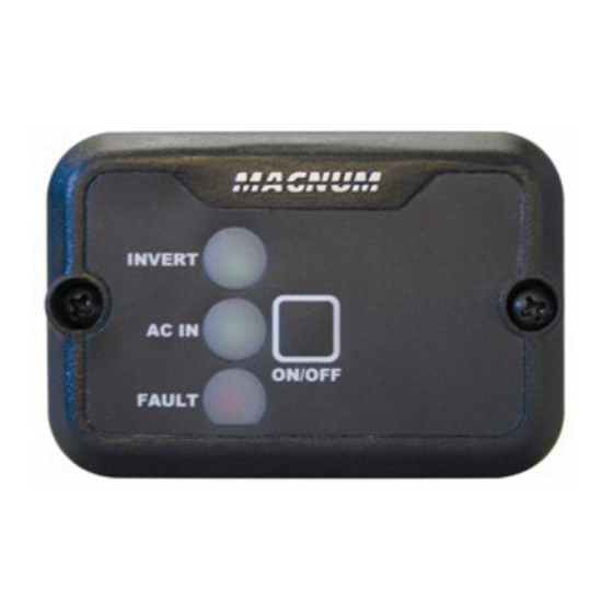
MM/MM-AE Series inverters’ Owner’s Manual. MM-R and MM-RC Remotes The three LED indicators on the left side of both the MM-R and MM- RC remotes (see Figure 7) will show you the operating status of the MM/MM-AE Series inverter. -
Page 13: Mm-Rc Remote Only
MM-RC Remote Only The MM-RC includes three additional charging LED indicators for information on the operation of the battery charger. Monitor the indicators (at least 10 seconds) to determine the charger status. © 2010 Magnum Energy, Inc. - Page 14 BTS – this ensures correct charging. ** These settings are preset by the inverter or the connected remote (see Table 1, Inverter and Remote Settings), but can be changed by the ME-RC50 remote. © 2010 Magnum Energy, Inc.
-
Page 15: Warranty And Service Information
4.0 Warranty and Service Information 4.0 Warranty and Service Information 24 Month Limited Warranty Magnum Energy, Inc., warrants the MM-R and MM-RC Remote Controls to be free from defects in material and workmanship that result in product failure during normal usage, according to the following terms and conditions: 1. - Page 16 Magnum Energy, Inc. 2211 West Casino Rd. Everett, WA 98204 Phone: (425) 353-8833 Fax: (425) 353-8390 Web: www.magnumenergy.com PN: 64-00012 Rev A © 2010 Magnum Energy, Inc.
Need help?
Do you have a question about the MM-R and is the answer not in the manual?
Questions and answers