
Related Manuals for Magnum Energy ME-RC


Summary of Contents for Magnum Energy ME-RC
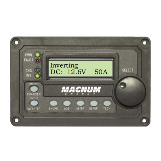
- Page 1 ME-RC Basic Remote Control Inverting DC: 12.6V Owner’s Manual (Revision 2.6 or higher)
- Page 2 If the ME-RC remote fails, it is reasonable to assume that the health of the user or other persons may be endangered.
-
Page 3: Table Of Contents
3.2.2 AGS Menu ................7 3.2.3 METER Menu ..............7 3.2.4 SETUP Menu ............... 8 3.2.5 TECH Menu ..............16 4.0 Menu Map: ME-RC Remote Control ..........18 5.0 Operation .................. 21 5.1 Front Panel ................21 5.1.1 LED Indicators ..............21 5.1.2 LCD Display .............. - Page 4 Figure 4-1, Inverter/Charger Menu Map ..........18 Figure 4-2, Inverter/Charger Menu Map ..........19 Figure 4-3, Inverter/charger Menu map ..........20 Figure 5-1, ME-RC Front Panel Controls and Indicators ......21 Figure 5-2, Off Mode ................ 24 Figure 5-3, Searching Mode .............. 24 Figure 5-4, Inverting Mode ...............
- Page 5 Figure 5-27, Internal Bridge Fault ............34 Figure 5-28, Internal Charger Fault ............ 34 Figure 5-29, Internal NTC Fault ............34 Figure 5-30, Internal Relay Fault ............34 Figure 6-1, Performing an Inverter Reset ..........38 ©2010 Magnum Energy, Inc.
-
Page 6: Overview
1.0 Overview 1.0 Overview The ME-RC remote control allows you to monitor and customize the operating parameters for your Magnum inverter/charger. It is the same remote used for all Magnum inverter/charger models in the ME, MM, MMS, MM-AE, MS, MS-AE, MS-PAE, and RD Series lines so there is no cross-platform confusion. -
Page 7: Installation
2.0 Installation 2.0 Installation Before proceeding, read the entire Installation section to determine how you are going to install your ME-RC. WARNING: Installations should be performed by qualifi ed per- sonnel, such as a licensed or certifi ed electrician. The installer is responsible for determining which safety codes apply and for ensuring that all applicable installation requirements are followed. -
Page 8: Figure 2-1, Remote Cut-Out Dimensions
8. Secure the remote to the wall using the four 6 x 3/4” screws provided. 9. The remote is ready for setup. Magnum Inverter RJ11 connection Remote cable Remote port (blue label) Figure 2-2, Remote Control Connections ©2010 Magnum Energy, Inc. -
Page 9: Setup
3.1 Navigating the Remote’s Menu The ME-RC has an internal structure that provides menu items and adjustable settings that provide the ability to confi gure your inverter/charger to your specifi... -
Page 10: Figure 3-2, Setup Menu Navigation
4. Turn the SELECT knob to the desired setting. When the bottom line shows the desired setting: Inverting BatType= AGM 1 5. Press the SELECT knob to save this desired setting. Figure 3-2, SETUP Menu Navigation ©2010 Magnum Energy, Inc. -
Page 11: Menu Pushbuttons And Menu Items
CAUTION: The Shore Max setting does not limit the current to the inverter loads. If the current from the loads on the output of the inverter are greater than the circuit breaker rating on the incoming AC source, you may experience nuisance tripping on this breaker. ©2010 Magnum Energy, Inc. -
Page 12: Ags Menu
— to be confi gured to your specifi c system preferences, and displays the status of the battery system. Info: Refer to the ME-BMK/BMK-NS Owner’s Manual (PN: 64- 0013) for detailed information on the Battery Monitor Kit and the available menus. ©2010 Magnum Energy, Inc. -
Page 13: Setup Menu
30 watts), the inverter will stop searching and start inverting to deliver power to the load. Info: Even though the Search feature is on, some connected equipment — even if they are off — may draw enough current to keep the inverter in the Inverting mode. ©2010 Magnum Energy, Inc. -
Page 14: Figure 3-7, Setup: 02 Lowbattcutout Selections
Info: If there is an AGS-N device installed, it should be set to start ≥1.0 volts higher than the LBCO setting – this is to prevent the inverter from shutting down before the generator comes on. ©2010 Magnum Energy, Inc. -
Page 15: Table 3-1, Battery Amphrs Capacity To Absorb Time
• Amp-hour (AH) capacity is a measurement of how many amps a battery can deliver for a specifi ed length of time (usually 20 hours) until the voltage achieves 1.75 VDC/cell at 80° F. ©2010 Magnum Energy, Inc. -
Page 16: Table 3-2, Battery Size To Battery Amphrs (Estimated)
‘series string’ and the amp-hour capacity doesn’t change. Each series string is connected together in parallel to increase the amp-hour capacity. Add the amp-hour capacity of each series string connected in parallel to determine the total amp-hour capacity of the battery bank. ©2010 Magnum Energy, Inc. -
Page 17: Table 3-3, Battery Type To Charge Voltages
Rotate to Rotate to desired Status... Press Press to select selection: Press to save 04 Battery Type Status ... Status ... Status ... Status..BatType=AGM1 BatType=Custom BatType=GEL BatType=Flooded Figure 3-9, SETUP: 04 Battery Type Selections ©2010 Magnum Energy, Inc. -
Page 18: Figure 3-10, Setup: 05 Charge Rate Selections
* C/5 or C/20 rate – Charge rates are commonly expressed as a ratio of the total amp-hour (AH) capacity of the battery bank. For example, with a 400 AH battery bank (C = 400), the C/5 charge rate is 80 A (400/5 = 80 A). ©2010 Magnum Energy, Inc. -
Page 19: Figure 3-11, Setup: 06 Vac Dropout Selections
For generator charging, do not use this setting. Info: If you get nuisance AC disconnects, either change the setting to 100 VAC or less (export inverter models - 200 VAC or less), or obtain a better voltage regulated AC source. ©2010 Magnum Energy, Inc. -
Page 20: Figure 3-12, Setup: 07 Power Save Selections
Contrast = 50% Contrast = 90% Contrast = 100% Status... Brightness =50% Rotate to desired Press to save selection: Status... Status... Status... Status ... Brightness= 0% Brightness=100% Brightness= 50% Brightness= 90% Figure 3-13, SETUP: 08 Screen Setup Selections ©2010 Magnum Energy, Inc. -
Page 21: Tech Menu
Info: When “Model: UNKNOWN” is displayed, the remote is not able to determine the inverter model due to an older inverter model, or an inverter revision newer than the remote. All remote menu selections and features that are available in the inverter will function normally. ©2010 Magnum Energy, Inc. -
Page 22: Table 3-4, Inverter/Charger Default Settings
TECH Rotate to Rotate to desired Status... Press to select Press display: 05 Ext Control Status... Status... Status... VAC Dropout : ** Charge Rate: ** Shore Max : ** Figure 3-18, TECH: 05 Ext Control Display ©2010 Magnum Energy, Inc. -
Page 23: Menu Map: Me-Rc Remote Control
4.0 Menu Map 4.0 Menu Map: ME-RC Remote Control The following fi gure is a complete overview of the inverter/charger settings and info displays available in the ME-RC; this should help with menu navigation. Range: 5A to 60A SHORE Default: 30A Status ... -
Page 24: Figure 4-2, Inverter/Charger Menu Map
Status ... Status ... Status ... Brightness = 0% Brightness = 10% Brightness = 20% Status ... Status ... Brightness = 100% Brightness = 50% Figure 4-1, Inverter/Charger Menu Map (Page 2 of 3) ©2010 Magnum Energy, Inc. -
Page 25: Figure 4-3, Inverter/Charger Menu Map
Inverter/Charger Status Status... Menu Items 01 Search Watts Press SELECT Inverter/Charger Status Status... Menu Selections Setting Search = 5W Notes: = current setting ** = read only display Figure 4-1, Inverter/Charger Menu Map (Page 3 of 3) ©2010 Magnum Energy, Inc. -
Page 26: Operation
LED indicators and LCD display. 5.1 Front Panel The ME-RC front panel contains LEDs and a LCD display for viewing system status, pushbuttons to control system operation, and a rotary knob that allows an easy way to select and fi nd system information. -
Page 27: On/Off Pushbuttons
SELECT knob to select a menu item or to save a setting once they are displayed on the LCD screen. Info: All adjustable inverter/charger settings in the ME-RC (ex- cept for the SHORE: Shore Max and SETUP: 08 Screen Setup settings –... -
Page 28: Operating The Inverter/Charger
To enable the Equalization charge, see Figure 5-11 and the info on page 27. ©2010 Magnum Energy, Inc. -
Page 29: System Status Messages
Inverting are on solid. The FAULT (red) and Settings/Info.. CHG (green) LEDs are off. Figure 5-4, Inverting Mode • Inverting - The inverter is providing AC voltage on its output by inverting power from the batteries. ©2010 Magnum Energy, Inc. -
Page 30: Charger Mode Messages
SETUP menu’s 04 Battery Type setting) while Bulk charging. During this stage, the DC charging current decreases in order to maintain the absorb voltage setting. This charge stage continues until the Absorb Charging time (determined by the SETUP menu’s 03 Battery AmpHrs setting) is fi nished. ©2010 Magnum Energy, Inc. -
Page 31: Figure 5-8, Float Charging Mode
Info: To enable charging again, press the ON/OFF CHARGER pushbutton. When the charger is again enabled, the charger will continue in the Charge mode it last left and the CHG (green) LED will come on solid. ©2010 Magnum Energy, Inc. -
Page 32: Figure 5-11, Equalizing Mode
Equalize charge. If in doubt, disconnect the DC loads to prevent damage. Info: Equalization charging is not available if GEL or AGM 2 is se- lected under the SETUP menu’s 04 Battery Type menu. ©2010 Magnum Energy, Inc. -
Page 33: Fault Mode Messages
34 VDC (24-volt models), or 68 VDC (48-volt models). Remedy: This fault usually occurs when an external DC source is charging the inverter’s battery bank. Turn off any other additional charging source to allow the DC voltage level to drop. ©2010 Magnum Energy, Inc. -
Page 34: Figure 5-14, Overtemp Fault
AC voltage (>150 VAC) has been detected on the AC input. Remedy: Remove all AC power from the inverter’s AC input for at least 15 minutes to automatically restart this fault. Ensure only 120VAC power is connected to each of the inverter’s AC inputs. ©2010 Magnum Energy, Inc. -
Page 35: Figure 5-17, Dead Battery Charge Fault
Once the AC loads are reduced or the output wiring is corrected, manually restart the inverter to resume operation. If this fault condition continues after all these recommendations, perform a inverter reset (see Section 6.2). ©2010 Magnum Energy, Inc. -
Page 36: Figure 5-19, Fet Overload Fault
Unknown Fault - This fault message displays when the inverter/charger has sent a fault code that cannot be determined by the remote. Remedy: Call the Technical Support department at Magnum Energy to assist you in determining and understanding the actual fault status. ©2010 Magnum Energy, Inc. -
Page 37: Figure 5-22, Tfmr Overtemp Fault
A fault condition may occur when two inverters are stacked in series — using the stacking interface — that is not possible on a single inverter installation. Refer to the following fault messages to help troubleshoot the inverters. ©2010 Magnum Energy, Inc. -
Page 38: Figure 5-24, Stackclock Fault
AC input source; 3. One of the inverter’s internal transfer relay is bad; or, 4. The inverter’s AC input circuit breaker may be open. Remedy: If this fault doesn’t clear after checking these four rec- ommendations, perform an inverter reset (see Section 6.2). ©2010 Magnum Energy, Inc. -
Page 39: Figure 5-27, Internal Bridge Fault
PWR (green), CHG (green), and INV Settings/Info.. (green) LEDs are off. Figure 5-30, Internal Relay Fault • Internal Relay - This fault message displays and the inverter shuts down because the internal AC transfer relay protection circuit has been activated. ©2010 Magnum Energy, Inc. -
Page 40: Led Indicator Guide
CHG LEDs are on); the inverter will automatically (green) supply AC power to the loads if shore or generator power is lost. Inverter is in Search mode (the AC load is below BLINKING the SETUP menu’s 01 Search Watts setting). ©2010 Magnum Energy, Inc. -
Page 41: Troubleshooting
Inverter is not Ensure inverter batteries are connected to connected and inverter is batteries. operating correctly without any AC power connected (can invert and power AC loads from batteries). ©2010 Magnum Energy, Inc. -
Page 42: Troubleshooting Tips
Charger says “Float Charging” not “Bulk Charging” when the AC is fi rst plugged in: Check the 01A DC Volts meter (p. 7) on the ME-RC display, if the battery is over 13.0 VDC (26.0 VDC for 24-volt models or 52.0 VDC for 48-volt models) then the battery was already charged, and the... -
Page 43: Performing An Inverter Reset
Info: The Power ON/OFF pushbutton is a small momentary type switch which operates by lightly pressing and releasing. Info: All adjustable inverter/charger settings in the ME-RC (ex- cept for the SHORE menu’s Shore Max and SETUP menu’s 08 Screen Setup settings - which revert back to default) are saved in nonvolatile memory and are preserved until changed –... -
Page 44: Limited Warranty
7.0 Service and Warranty Info 7.0 Service and Warranty Info Magnum Energy, Inc. warrants the ME-RC remote control to be free from defects in material and workmanship that result in product failure during normal usage, according to the following terms and conditions. -
Page 45: How To Receive Repair Service
7.1 How to Receive Repair Service If your product requires warranty service or repair, contact either: An Authorized Service Center, as listed on the Magnum Energy website at http://www.magnumenergy.com/ServiceCenters.htm, or Magnum Energy, Inc. at: Telephone: 425-353-8833 Fax: 425-353-8390 Email: warranty@magnumenergy.com If returning your product directly to Magnum Energy for repair, you must: •... - Page 46 Magnum Energy, Inc. 2211 West Casino Rd Everett, WA 98204 Phone: 425-353-8833 Fax: 425-353-8390 Web: www.magnumenergy.com PN: 64-0003 Rev E...
Need help?
Do you have a question about the ME-RC and is the answer not in the manual?
Questions and answers