
Related Manuals for Magnum Energy ME-ARC Series


Summary of Contents for Magnum Energy ME-ARC Series
- Page 1 ME-ARC Advanced Remote Control Owner’s Manual (Version 5.0 or higher: with AGS, BMK, ACLD, and PT info)
- Page 2 Thank you from all of us at Sensata Technologies for purchasing this ME-ARC remote. We under- stand that you have many purchasing options in the marketplace, and we are pleased that you have decided on this Magnum Energy product. At Sensata, we are committed to providing you with quality products and services, and hope that your experience with us is pleasant and professional.
- Page 3 Magnum inverters. As long as AC power is connected, it will pass through the inverter regardless of the power switch on the inverter or the ON/OFF INVERTER button on the remote. © 2021 Magnum Energy, Inc. Page ii...
-
Page 4: Table Of Contents
Software Diff erences Between AGS Versions ...........61 Setting Up the AGS using the ME-ARC ............62 7.1.2 AGS Functional Tests ...................74 Operating/Monitoring the AGS using the ME-ARC ..........75 7.2.1 Operating the AGS ..................75 7.2.2 Enabling the AGS ..................76 Page iii © 2021 Magnum Energy, Inc. - Page 5 PT Controller Fault Message Screens ............125 10.3.2 Resolving PT Faults using the ME-ARC ............125 Remote Feature to Inverter Compatibility ........128 Limited Warranty ................134 How to Receive Repair Service ..............134 © 2021 Magnum Energy, Inc. Page iv...
- Page 6 Figure 10-2, Hold CV Charge Volts (PT Controller) ............105 Figure 10-3, Multi-Stage Charging (PT Controller) ............106 Figure 10-4, PT Fault History Screens ................117 Figure 10-5, PT Charge Controller CTRL/METER Menu Map ..........118 Page v © 2021 Magnum Energy, Inc.
- Page 7 Table 10-3, PT Remote Relay Statuses ................122 Table 10-4, PT Remote Fault Statuses ................123 Table 10-5, PT Remote Power Statuses ................. 124 Table A-1, ME-ARC (Version 5.0) Compatibility Matrix ............. 128 © 2021 Magnum Energy, Inc. Page vi...
-
Page 8: Overview
Pressing the rotary knob allows you to select a menu item, or to save a setting once it is displayed on the LCD. Page 1 © 2021 Magnum Energy, Inc. -
Page 9: Installation
Eight #8 x 3/4 Phillips screws • ME-ARC Owner’s Manual If items appear to be missing or damaged, contact your authorized Magnum Energy dealer or Magnum Energy. IMPORTANT: Save your proof-of-purchase as a record of your ownership; it is needed if the unit should require in-warranty service. -
Page 10: Connecting The Remote Cable
REMOTE (blue) port on the Magnum inverter/charger (see Figure 2-2). Note: Do not connect the remote cable at this time. First, locate and prepare an area to mount the remote (follow directions in Section 2.4). Figure 2-2, Remote Control Connections Page 3 © 2021 Magnum Energy, Inc. -
Page 11: Me-Arc Remote And Bezel Dimensions
(3.8 cm) 5 ⅞" (14.9 cm) 5 ¼" (13.3 cm) 4 ⅜" (11.1 cm) 4 ⅜" (11.1 cm) Cut out tab to run remote cable flush to surface Figure 2-4, Remote Bezel Dimensions © 2021 Magnum Energy, Inc. Page 4... -
Page 12: Mounting The Me-Arc Remote
5. If the self test is successful, secure the ME-ARC to the wall using four of the supplied Phillips screws. If the self test is unsuccessful, refer to the Troubleshooting section. 5.0" (12.7 cm) 3.0" (7.6 cm) Figure 2-5, Flush Mounting the ME-ARC Page 5 © 2021 Magnum Energy, Inc. -
Page 13: Surface Mount Installation Procedure
7. If the self test is successful, secure the ME-ARC to the bezel using four of the supplied Phillips screws. If the self test is unsuccessful, refer to the Section 6.0 “Troubleshooting”. Remote cable Figure 2-6, Surface Mounting the ME-ARC using the Bezel © 2021 Magnum Energy, Inc. Page 6... -
Page 14: Power-Up Self Test
When the ME-ARC is first connected to an inverter, a power-up self test is initialized. During the self test, the LCD automatically displays in sequence: • “MAGNUM ENERGY Self Test”, then • “(C)2020-2025, Connecting to...”, and then •... -
Page 15: Setup
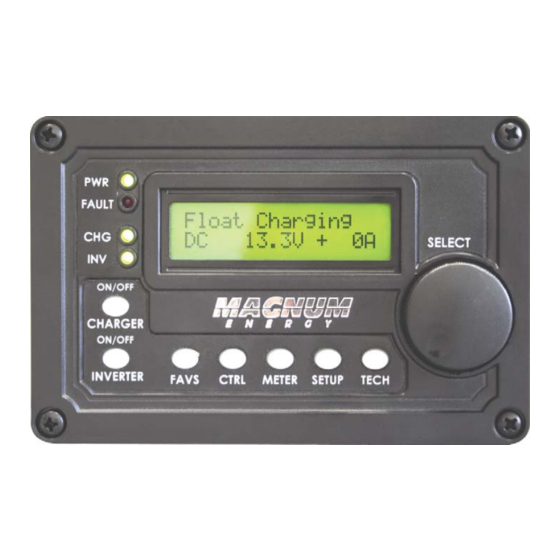
Info: Hold down the SELECT knob for 10 seconds to refresh the LCD display. Float Charging 13.34V + 0A Menu Rotary LCD Display Buttons SELECT Knob Figure 3-1, Front Panel Setup Features © 2021 Magnum Energy, Inc. Page 8... -
Page 16: Figure 3-2, Setup Menu Navigation
Rotate the SELECT knob to the desired setting. When the bottom line shows the Set Search Watts desired setting: 10 Watts 5. Press the SELECT knob to save this setting. Figure 3-2, SETUP Menu Navigation Page 9 © 2021 Magnum Energy, Inc. -
Page 17: Remote Buttons And Menu Items
Info: If the menu selected to be stored under the FAVS button is not a valid option, the remote displays “Cannot be FAV”. Status Example: 02 Invert Setup is a menu heading. 02 Invert Setup 02A Search Watts Example: 02A Search Watts is a menu item. 5 Watts © 2021 Magnum Energy, Inc. Page 10... -
Page 18: Favs Button And Menus
. If another menu item is saved in the F5 location, the only way to bring Gen Control back into the F5 location is to reset the remote to its factory defaults using the TECH: 08 Load Defaults menu (page 41). Page 11 © 2021 Magnum Energy, Inc. -
Page 19: Ctrl (Control) Button And Menus
ACIn Control Rotate to Auto Connect desired Bottom line Press to edit Press selection: shows current setting setting 02 CHG Control 03 Gen Control 04 PT Control Figure 3-4, CTRL Button and Menus © 2021 Magnum Energy, Inc. Page 12... - Page 20 See SETUP menu 02E for more information on the Set Connect SOC menu settings. • ACIn - Disabled – Disconnects incoming AC when selected. This setting will prevent incom- ing AC from connecting to the inverter/charger. Page 13 © 2021 Magnum Energy, Inc.
- Page 21 04 PT Control is used for controlling a charge controller that is connected to the system. See Sec- tions 10.1 and 10.2 for information on setting up the PT charge controller using the ME-ARC’s SETUP and CTRL buttons. © 2021 Magnum Energy, Inc. Page 14...
-
Page 22: Meter Button And Menus
AC output voltage as a nominal 120-volt value. To calculate: add the voltage from each hot out (i.e., HOT 1 to NEUTRAL and HOT 2 to NEUTRAL) and divide by two. Page 15 © 2021 Magnum Energy, Inc. - Page 23 Info: If the 02F Input AC2 menu displays voltage (~ 50v), but the generator is off or nothing is connected to the AC2 input, the AC2 neutral-to-ground bond connection is not correct or not connected. © 2021 Magnum Energy, Inc. Page 16...
-
Page 24: Figure 3-6, Current Flow - Inverter Mode
= -10 Amps AC 02C Input Amps 02B Load Amps 20AAC Inverter 10 Amps AC 20 Amps AC TO LOADS Amp meters 02D Inv/Chg Amps -10 Amps AC Figure 3-8, Current Flow – Load Support Mode Page 17 © 2021 Magnum Energy, Inc. -
Page 25: Setup Button And Menus
SETUP menus. After fi ve minutes from the last button push, the display automatically returns to the remote’s Home screen and the PIN must be reentered in order to access the SETUP menus. Refer to the TECH: 05 SETUP PIN section for more information. © 2021 Magnum Energy, Inc. Page 18... -
Page 26: Figure 3-9, Setup Button And Menus
Power Save feature off by selecting OFF from the Pwr Save menu option. Info: Pressing the SELECT knob causes the remote to exit Power Save mode. However, rotating the SELECT knob will not cause the remote to come out of Power Save mode. Page 19 © 2021 Magnum Energy, Inc. - Page 27 , then the Search Watts feature should be used. However, if some small loads (i.e., digital clocks, satellite receivers, answering machines, etc.,) are required to be on, then this feature should be turned off (Set Search Watts = OFF). © 2021 Magnum Energy, Inc. Page 20...
- Page 28 AC power to be connected and used until the disconnect setting is reached. 3. When using a dual source inverter/charger such as the MSH4024RE, the AC In control features only work with the GRID IN (AC1) input. Page 21 © 2021 Magnum Energy, Inc.
- Page 29 (and to charge the battery). When the energy source can again deliver enough power to raise the battery voltage to the Disconnect volts setting, the inverter disconnects from the utility and again powers the inverter loads from the battery. © 2021 Magnum Energy, Inc. Page 22...
- Page 30 Disconnect SOC setting or the inverter may not disconnect from the incoming AC because the battery may not be charged to a high enough SOC level to meet the Disconnect SOC setting. Page 23 © 2021 Magnum Energy, Inc.
- Page 31 Default setting: 30 Amps Ranges: 5-60 Amps (one amp increments) Settings for MSH4024RE: ◊ Set AC Input Amps (AC1 and AC2) Default settings: AC1=30 Amps, AC2=20 Amps Ranges: 5-60 Amps (one amp increments) © 2021 Magnum Energy, Inc. Page 24...
- Page 32 ◊ Set VAC Dropout (AC1 only) – Sets at what AC voltage—from the HOT IN 1 to NEUT IN 1 terminals—the inverter/charger will connect to or disengage from the incoming AC. Default setting: 80 VAC (150 VAC for export models) Range: 60-100 VAC, UPS Mode Page 25 © 2021 Magnum Energy, Inc.
- Page 33 BTS is below 77°F (25°C), and decrease if higher than 77°F (25°C). This ensures the batteries receive the correct charge voltage regardless of temperature. © 2021 Magnum Energy, Inc. Page 26...
- Page 34 Info: The LFP battery type selection forces the charger to go into the Bulk charge mode each time AC is connected. If AC is reconnected less than two minutes after being disconnected, the charger will return to the previous charge mode. Page 27 © 2021 Magnum Energy, Inc.
-
Page 35: Table 3-1, Battery Type To Charge Voltages (Fi Xed Voltage)
BTS is below 77° F (25° C), and decrease if higher than 77° F (25° C). This ensures the batteries receive the correct charge voltage regardless of temperature. © 2021 Magnum Energy, Inc. Page 28... - Page 36 BMK (under METER: 05D DC Amps-BMK) will be used by the CC/CV’s Max Charge Amps setting instead of the inverter’s DC calculated current (shown under METER: 01B DC Amps)—as it is more accurate (+/- .1 ADC). Page 29 © 2021 Magnum Energy, Inc.
-
Page 37: Figure 3-10, Cv Charge Done Time/Amps Stages (Inv/Chg)
C/20, where C=Battery Bank’s To- tal Amp Hours. Basically, they take approximately 5% of the total battery bank size and consider the battery totally charged when the charger’s return amps drops to this level. © 2021 Magnum Energy, Inc. Page 30... -
Page 38: Table 3-2, Battery Amp/Hrs Capacity To Suggested Absorb Time
DC volts level that you want the batteries to fall before starting a new charge. Default: 12.0 VDC (12v), 24.0 VDC (24v), 48.0 VDC (48v) Range: 12.0-16.0 VDC (12v), 24.0-32.0 VDC (24v), 48.0-64.0 VDC (48v) Page 31 © 2021 Magnum Energy, Inc. -
Page 39: Figure 3-11, Hold Cv Chg Vdc Charge Stages (Inv/Chg)
EQ Volts setting (≤0.1v/12-volt systems, ≤0.2v/24-volt systems, or ≤0.4v/48-volt systems); b) Pauses when in Charger Standby; c) Clears when EQ is fi nished, the battery goes to Bulk/Absorb or Float, or EQ is stopped. © 2021 Magnum Energy, Inc. Page 32... - Page 40 If a battery monitor is not installed, the Absorb Done Amps setting relies on the METER: 01B DC Amps value to determine when to transfer out of the Absorption charge mode. This is the most accurate DC amperage measurement. Page 33 © 2021 Magnum Energy, Inc.
- Page 41 * C/5 or C/20 rate – charge rates are commonly expressed as a ratio of the total amp-hour (AH) capacity of the battery bank. For example, with a 400 AH battery bank (C = 400), the C/5 charge rate is 80 A (400/5 = 80 A). © 2021 Magnum Energy, Inc. Page 34...
- Page 42 The charger will continue to cycle between Float and Full Charge as long as incoming AC is available. See Figure 3-12. Note: These battery voltages are the fully charged voltages of a battery at rest. Page 35 © 2021 Magnum Energy, Inc.
-
Page 43: Figure 3-12, Final Charge Stage - Multi-Stage
Setup Figure 3-12, Final Charge Stage – Multi-Stage Figure 3-13, Final Charge Stage – Float Figure 3-14, Final Charge Stage – Silent © 2021 Magnum Energy, Inc. Page 36... - Page 44 Note: If “CC/CV Controlled” displays on this menu’s screen, you will not be able to adjust the settings as “CC/CV” has been selected as the battery type from the 03C Battery Type menu. Info: Once equalizing begins, the METER: 03C Since EQ Start timer resets to zero days. Page 37 © 2021 Magnum Energy, Inc.
- Page 45 SETUP: 04 AGS Setup/SETUP: 05 BMK Setup/SETUP: 06 PT Setup Refer to Sections 7.0, 8.0, and 10.0 respectively for detailed information on the AGS/BMK/PT SETUP menus that are available from the ME-ARC remote’s SETUP button. © 2021 Magnum Energy, Inc. Page 38...
-
Page 46: Tech Button And Menus
ME-ARC will be available. The ME-ARC has limited functions as a second remote connected to a router. Refer to the ME-RTR Owner’s Manual (PN: 64-0020) for a complete list of active menus when the ME-ARC is connected to a router. Page 39 © 2021 Magnum Energy, Inc. -
Page 47: Figure 3-16, Inverter Fault History Screens
CAUTION: Before using the Clear Faults feature, be sure you do not want the fault history data for any device (inverter, AGS, or PT controller). Once fault history data has been cleared, it cannot be retrieved © 2021 Magnum Energy, Inc. Page 40... - Page 48 PIN number. Once you enter the SETUP menus in FAVS, the PIN number can be entered and the SETUP button is locked. The SETUP menus in FAVS are now accessible without having to enter the PIN number. See FAVs button info. Page 41 © 2021 Magnum Energy, Inc.
-
Page 49: Table 3-3, Inverter/Charger Default Settings On Me-Arc
LECT knob until “PIN = 0000” displays (approximately 7 seconds). Enter a new PIN number. TECH: 06 Ext Control External Control is a read only menu. Magnum Energy has adopted an open protocol policy which allows certain functions of the inverter/charger to be controlled externally—such as with a third party communications device. -
Page 50: Menu Maps: Me-Arc Remote Control
O5 BMK Meters [Status/Fault] Refer to ACLD METER menu maps in Section 9.2.3 O6 ACLD Meters [Status/Fault] Refer to PT METER menu maps in Section 10.2.3 O7 PT Meters Figure 4-1, FAVS/CTRL/METER Button Menu Maps Page 43 © 2021 Magnum Energy, Inc. -
Page 51: Figure 4-2, Setup Button Menu Map
80% to 100% SOC Range: 20% to 99% Range: 21% to 100% 02F Power Up Set Power Up Always OFF Always = SETUP button menu map continues on next page Figure 4-2, SETUP Button Menu Map © 2021 Magnum Energy, Inc. Page 44... -
Page 52: Figure 4-3, Setup Button Menu Map
0-250 ADC Set Max CC/CV OFF, 0.1-25.5 Hrs Time = 12.0 Hrs Set Recharge 12.0-16.0 VDC Volts = 12.0 SETUP button menu map continues on next page Figure 4-3, SETUP Button Menu Map Page 45 © 2021 Magnum Energy, Inc. -
Page 53: Figure 4-4, Setup/Tech Button Menu Maps
Read Only displays Remo te: 02 Versions 02 V ersions AGS: Inverter: Pres s SELECT BMK: Rout er: ACLD : TECH button menu map continues on next page Figure 4-4, SETUP/TECH Button Menu Maps © 2021 Magnum Energy, Inc. Page 46... -
Page 54: Figure 4-5, Tech Button Menu Map
Set Search Watts Default/Current 5 Watts Setting Rotate SELECT = current setting* = Settings/Range OFF, 5A-60A * For this menu map, the arrow denotes the factory default setting Figure 4-5, TECH Button Menu Map Page 47 © 2021 Magnum Energy, Inc. -
Page 55: Operation
The green CHG LED turns on and off with the button. This button is also used to initiate an Equalize charge. For more information on using the Equalize Charging feature, see “Equalizing” under Section 5.3.2. © 2021 Magnum Energy, Inc. Page 48... -
Page 56: Menu Buttons
ON/OFF INVERTER button to turn the inverter function off . If the green INV LED is off , inverter power will NOT be available to run your critical loads if the external AC power is interrupted. Page 49 © 2021 Magnum Energy, Inc. -
Page 57: Charger Mode
If the CHG LED on: Settings/Info... message scrolls with See Section 5.3.2 a secondary screen Only INV LED on: message, refer to See Section 5.3.1 Section 5.3.3. Figure 5-2, System Status Screen (Example) © 2021 Magnum Energy, Inc. Page 50... -
Page 58: Inverter Mode Status Messages
Unknown Mode ## – This status message displays when the inverter/charger has sent an operational status code that the ARC remote does not identify. Remedy: Call Technical Support at Magnum Energy (425-353-8833) for assistance in identifying and understanding the actual fault status. - Page 59 How long should I equalize? While the batteries are gassing, monitor the specifi c gravity read- ings every hour. When the specifi c gravity readings no longer increase, the Equalization charge is complete and should be stopped. © 2021 Magnum Energy, Inc. Page 52...
-
Page 60: Secondary Scrolling Status Messages
Note: Requires that the optional ME-AGS-N Auto Gen Start controller be installed. • Max Charge Time – The charger has fi nished Absorption charge mode as the 03F Max Charge Time setting has been exceeded. Page 53 © 2021 Magnum Energy, Inc. -
Page 61: Fault Mode Messages
Info: While in Charger mode, the inverter’s AC input breaker could nuisance trip if the loads on the inverter’s output exceeds the current rating of the inverter’s input circuit breaker. © 2021 Magnum Energy, Inc. Page 54... - Page 62 (see Sections 6.2 & 6.3). Remedy: After performing the reset, turn the inverter on. If the fault does not clear after the reset, the inverter may require service. Page 55 © 2021 Magnum Energy, Inc.
- Page 63 (see Section 6.2). If the fault continues, disconnect all the inverter’s AC output wires and perform a power reset (Section 6.3). If this fault does not clear after doing the power reset, the inverter will require service. © 2021 Magnum Energy, Inc. Page 56...
- Page 64 (listen and make sure you hear an audible “click” from the connectors at both inverters). Info: This fault has been known to occur when a Magnum Energy accessory is plugged into the Stack Port, but the installation is not using multiple inverters in a stacked confi...
-
Page 65: Led Indicator Guide
AC power to the loads if utility or generator power is lost. Inverter is in Search mode (the AC load is below the SETUP: BLINKING 02A Search Watts setting). © 2021 Magnum Energy, Inc. Page 58... -
Page 66: Troubleshooting
Inverter is not Ensure the inverter batteries are connected to the connected and the inverter is operating batteries. correctly without any AC power connected (can invert and power AC loads from batteries). Page 59 © 2021 Magnum Energy, Inc. -
Page 67: Troubleshooting Tips
(BTS) temperature. If the BTS is installed, the charge voltage settings will increase if the temperature around the BTS is below 77°F (25°C), and decrease if the temperature around the BTS is higher than 77°F (25°C). © 2021 Magnum Energy, Inc. Page 60... -
Page 68: Using A Me-Ags-N Controller
04K Gen 100% SOC Start Days** ≥ Ver 5.3 TECH: 04 Fault History 04B AGS Faults ≥ Ver 5.0 * Only MS-PAE, MS-PE, or MSH Series inverters ** Requires the ME-BMK (Battery Monitor) Page 61 © 2021 Magnum Energy, Inc. -
Page 69: Setting Up The Ags Using The Me-Arc
<100% for a set 100% SOC Start Days # of days Note¹: Only applicable to MS-PAE, MS-PE and MSH inverters. Note²: Autostart/stop conditions using SOC require a ME-BMK to be installed. © 2021 Magnum Energy, Inc. Page 62... - Page 70 If you are unsure what loads might be running or where to set the start delay, error on setting a shorter time such as a default of two minutes (to protect batteries from over-discharge). Page 63 © 2021 Magnum Energy, Inc.
- Page 71 Range: 0-127 Sec, 1-127 Min (1-sec increments up to 127 sec, then 1-min increments) Note¹: When the inverter’s BTS is connected, the actual absorb charge voltage will increase or decrease to ensure correct charging as the battery temperature changes. © 2021 Magnum Energy, Inc. Page 64...
- Page 72 Set Stop Amps Delay – This setting determines the amount of time that the AC load must continuously remain below the Stop Gen AC Amps setting before the generator autostops. Default setting: 120 Sec Range: 0-127 Sec, 1-127 Min (1-sec increments up to 127 sec, then 1-min increments) Page 65 © 2021 Magnum Energy, Inc.
- Page 73 If the charger is allowed to exit the Bulk/Absorption charge mode (i.e., go to Float/Silent), the battery SOC may never reach 100%. Note¹ – For a 4000 watt inverter, set Start Gen AC Amps at 25A. © 2021 Magnum Energy, Inc. Page 66...
- Page 74 Default setting: 2.0 Hrs Range: 0.5-25.5 Hrs (0.5 hour increments) Info: The Run Time in this menu uses the METER: 04C Gen Run Time menu’s displayed value to determine the generator’s run time. Page 67 © 2021 Magnum Energy, Inc.
- Page 75 Gen Run Temp Time setting. This means you could set the time to the lowest time setting (0.5 Hrs), knowing the generator will attempt to run until the temperature setting is met. © 2021 Magnum Energy, Inc. Page 68...
- Page 76 ◊ Set Stop Quiet Hour – Set the hour for Quiet Time to stop. ◊ Set Stop Quiet Minute – Set the minute for Quiet Time to stop. ◊ Set Stop Quiet AM-PM – Set AM or PM for the stop of Quiet Time. Page 69 © 2021 Magnum Energy, Inc.
- Page 77 Note¹: This voltage is scaled depending on your battery system; ≤0.3 for 12-volt systems, ≤0.6 for 24-volt systems, and ≤1.2 for 48-volt systems. Note²: Requires the optional Battery Monitor Kit (ME-BMK or ME-BMK-NS) to be installed and enabled. © 2021 Magnum Energy, Inc. Page 70...
- Page 78 Info: The Gen Exercise feature identifi es the number of days since the generator has last run by using the Since Gen Run Days timer which is shown under the METER: 04E Since GenRun display. Page 71 © 2021 Magnum Energy, Inc.
- Page 79 AC input from connecting. Also, when either warm- up or cooldown is activated, any AC source (i.e., grid or generator) connected to the inverter’s AC input will disconnect until the time period (warm-up or cooldown) is over. © 2021 Magnum Energy, Inc. Page 72...
- Page 80 If the charger is allowed to exit the Bulk/Absorption charge mode (i.e., go to Float/Silent), the battery SOC may never reach 100%. Page 73 © 2021 Magnum Energy, Inc.
-
Page 81: Ags Functional Tests
AGS by setting the remote’s 03 Gen Control setting to “AUTO” (see Section 7.2.1). If the ME-ARC displays a generator fault, or the AGS’s STATUS LED continues to blink or shows a fault condition (solid red LED indication), refer to your AGS owner’s manual for assistance. © 2021 Magnum Energy, Inc. Page 74... -
Page 82: Operating/Monitoring The Ags Using The Me-Arc
(i.e., Cooldown). Info: If the generator is manually started from the generator control panel or a generator remote panel, selecting OFF on the ME-ARC remote may not shut down the generator. Page 75 © 2021 Magnum Energy, Inc. -
Page 83: Enabling The Ags
Press the ME-ARC remote’s METER button, rotate the SELECT knob to the 04 AGS Meter menu, and then press the SELECT knob to access the AGS meter’s read-only menus. Rotate the SELECT knob to view the various AGS meters. © 2021 Magnum Energy, Inc. Page 76... - Page 84 The ME-AGS-N (≥Ver 5.3): resets to 0.0 when another generator autostart is triggered. Info: This display is used by the SETUP: 04F Max Gen Run Time menu to determine the generator’s maximum run time when started automatically. Page 77 © 2021 Magnum Energy, Inc.
- Page 85 This menu displays how many hours the generator has run since this “hour meter” was last reset. This menu is helpful if you would like to keep track of how long the generator has run from a specifi c point; for example, after the generator has been serviced. © 2021 Magnum Energy, Inc. Page 78...
-
Page 86: Figure 7-1, Ags Fault History Screens
Day(s) since fault occurred Fault Temp AGS DC voltage H1 14.2 VDC at time of fault Fault history number AGS temp Fault Temp sensor at time of fault Figure 7-1, AGS Fault History Screens Page 79 © 2021 Magnum Energy, Inc. -
Page 87: Starting And Stopping The Generator
Gen Run VDC settings are used to determine when the generator will autostop. If 04A Gen Run VDC is set to OFF, the Start/Stop Volts Delay and Stop Gen Volts values that were entered prior to selecting OFF will still be used to autostop the generator. © 2021 Magnum Energy, Inc. Page 80... -
Page 88: Ags Menu Maps
Days = OFF Default/Current Setting … = rotate SELECT knob = all screens not included ** For this menu map, the arrow denotes the factory default settings Figure 7-2, AGS CTRL/METER Menu Map (Section 1) Page 81 © 2021 Magnum Energy, Inc. -
Page 89: Figure 7-3, Ags Setup Menu Map (Section 2)
Set Stop Amps Set Stop Amps Set Stop Amps Delay = 0 Sec Delay = 120 Sec Delay = 127 Min SETUP Menu continues on next page Figure 7-3, AGS SETUP Menu Map (Section 2) © 2021 Magnum Energy, Inc. Page 82... -
Page 90: Figure 7-4, Ags Setup Menu Map (Section 3)
00:00P Set Quiet Time Set Quiet Time Set Quiet Time Topoff = 30Min Topoff = 120Min Topoff = OFF SETUP Menu continues on next page Figure 7-4, AGS SETUP Menu Map (Section 3) Page 83 © 2021 Magnum Energy, Inc. -
Page 91: Figure 7-5, Ags Setup/Tech Menu Map (Section 4)
Press SELECT AGS Fault... AGS Fault... AGS Fault... 00.0 VDC D- 0 HH:MM Each AGS fault has 3 screens. See Figure 7-1 for more info. Figure 7-5, AGS SETUP/TECH Menu Map (Section 4) © 2021 Magnum Energy, Inc. Page 84... -
Page 92: Ags Remote Status Messages
Ready The CTRL: 03 Gen Control menu is set to AUTO, and the AGS is ready to autostart the generator based on the active autostart settings under the SETUP: 04 AGS Setup menus. Page 85 © 2021 Magnum Energy, Inc. -
Page 93: Table 7-4, Ags Remote Start Statuses
Fault Topoff Generator failed to autostart in Start Topoff mode. Fault VDC Generator failed to autostart in Start VDC mode. Fault 100% SOC Generator failed to autostart in 100% SOC Start Days mode. © 2021 Magnum Energy, Inc. Page 86... -
Page 94: Table 7-6, Ags Default Settings On Me-Arc
(e.g., Start Gen AC Amps) is satisfi ed by its autostop condition (e.g., Stop Gen AC Amps). Once the generator has completed this autostart/autostop cycle, the AGS immediately begins to monitor for any active autostart/autostop settings again. Page 87 © 2021 Magnum Energy, Inc. -
Page 95: Ags Troubleshooting Using The Me-Arc
AGS controller is getting power. 2. Ensure the communications cable is connected from the Network port on the Magnum inverter to the NETWORK port on the ME-AGS-N. 3. Ensure you have the correct communications cable. © 2021 Magnum Energy, Inc. Page 88... -
Page 96: Resolving Ags Faults Using The Me-Arc
Info: The Max Gen Run Time menu uses the SETUP: 04B Gen Run Time display to determine the generator’s run time. Cooldown and warm-up times are not included in the Gen Run Time display. Page 89 © 2021 Magnum Energy, Inc. -
Page 97: How To Clear Ags Faults
CAUTION: Before using the Clear Faults feature, be sure you do not want the fault history for any device (inverter, AGS, or PT controller). Once fault history data has been cleared, it cannot be retrieved © 2021 Magnum Energy, Inc. Page 90... -
Page 98: Using A Bmk
Using a BMK: Setup Using a BMK This section discusses how to set up and monitor Magnum’s BMK (battery monitor kit) using the menu options in the ME-ARC remote. IMPORTANT: A BMK must be connected and communicating with the ME-ARC in order to set up and/or monitor its operation. -
Page 99: Bmk Operation/Monitoring With The Me-Arc
fi ciency value is recalculated and the Amp Hours In/Out read-out resets to the recalculated value. Info: To maintain the accuracy of the METER: 05B Battery SOC display and to keep the batteries in good condition, charge the batteries to 100% occasionally (~ x1/week). © 2021 Magnum Energy, Inc. Page 92... -
Page 100: Monitoring The Bmk Using The Me-Arc
Auto setting, the AH I/O value is recalculated after the battery has been fully charged (100% SOC) and ≥0.5% of the battery capacity has been discharged. If the sense module is disconnected from power, the AH I/O value resets to zero. Page 93 © 2021 Magnum Energy, Inc. - Page 101 However, they automatically synchronize once the BMK’s METER: 05B Battery SOC menu reaches 100% SOC (or you can manually synchronize by momentarily removing the network cable from the BMK). © 2021 Magnum Energy, Inc. Page 94...
-
Page 102: Bmk Menu Maps
(press and hold the SELECT knob for 3 seconds to reset values) = rotate SELECT knob = Current setting** ** - For this menu map, the arrow denotes the factory default settings Figure 8-2, BMK METER/SETUP Menu Map Page 95 © 2021 Magnum Energy, Inc. -
Page 103: Bmk Remote Status Messages
The BMK has lost its factory-set internal calibration reference. Power-up Fault A fault occurred during the BMK’s power-up sequence. Unknown Fault ## A fault code that is not recognized by the remote. No Comm Refer to Table 8-1 above. © 2021 Magnum Energy, Inc. Page 96... -
Page 104: Figure 8-3, Bmk Fault Message (Example)
Factory Fault – The BMK has lost its factory-set internal calibration reference. Remedy: Reset the battery monitor by removing all power from the BMK. If the fault remains or returns after resetting, the BMK will require repair at a Magnum Energy factory service facility. -
Page 105: Using An Acld
This read-only menu displays the voltage regulation set-point after it has been compensated based on the battery temperature sensor (BTS) reading shown. METER: 06E ACLD Version This read-only menu displays the software version of the ACLD controller. © 2021 Magnum Energy, Inc. Page 98... -
Page 106: Me-Arc Remote's Acld-Specifi C Tech Menus
Menu Button METER Press button Inverter/Charger Status [Status/Fault] 06 ACLD Meters Menu Item Press SELECT Menu Selection 06A ACLD Status [Status/Fault] ACLD Status/Meter R = rotate SELECT knob Figure 9-1, ACLD METER Menu Map Page 99 © 2021 Magnum Energy, Inc. -
Page 107: Acld Remote Status Messages
While in this status, if the battery voltage falls to a very low level, another Bulk/Absorb regulation stage will start. * – These settings are determined by the battery type settings in the Magnum inverter—which are communicated to the ACLD. © 2021 Magnum Energy, Inc. Page 100... -
Page 108: Acld Troubleshooting Using The Me-Arc
Remedy: This fault requires a reset of the ACLD. Press the ON/OFF switch on the side of the ACLD controller to remove power to the unit, and then press the ON/OFF switch again to restore power. If fault recurs, contact Magnum Energy for service. •... -
Page 109: Using A Pt Charge Controller
Because settings can be automatically changed once CC/ CV has been selected, if a diff erent battery type is selected, then all charge settings must be reviewed to ensure they are correct for the new battery type selection. © 2021 Magnum Energy, Inc. Page 102... - Page 110 fi nd out what the correct return amp settings are for your batteries. Note: After choosing Set CV Chg Done Amps, the Set Max CC/CV Time and Set Recharge Volts settings must be determined (see next page). Default: 20 ADC Range: 0-250 ADC Page 103 © 2021 Magnum Energy, Inc.
-
Page 111: Figure 10-1, Cv Charge Done Time/Amps (Pt Controller)
48.8 VDC (48-volt systems), respectively. Default: 12.0 VDC (12v), 24.0 VDC (24v), 48.0 VDC (48v) Range: 9.0-16.0 VDC (12v), 18.0-32.0 VDC (24v), 36.0-64.0 VDC (48v) Figure 10-1, CV Charge Done Time/Amps (PT Controller) © 2021 Magnum Energy, Inc. Page 104... -
Page 112: Figure 10-2, Hold Cv Charge Volts (Pt Controller)
EQ Volts setting, and clears when the controller status goes to Float Charging. It clears automatically when the EQ charging fi nishes, or can be manually cleared by selecting Float Start (under the CTRL: 04A PT CHG Ctrl menu). Page 105 © 2021 Magnum Energy, Inc. -
Page 113: Figure 10-3, Multi-Stage Charging (Pt Controller)
Check with your battery manufacturer to fi nd out what the correct return amp settings are for your batteries. Default setting: 20 ADC Range: 0-250 ADC © 2021 Magnum Energy, Inc. Page 106... - Page 114 The Max Charge Rate setting only limits the charging on each controller individually, not on all controllers. Page 107 © 2021 Magnum Energy, Inc.
- Page 115 11.0 VDC - 11.5 VDC (for a 12-volt system). Info: The Bulk Start – Volts feature uses the DC voltage displayed from the METER: 07C Bat Volts-PT menu to determine when to start another Bulk cycle. © 2021 Magnum Energy, Inc. Page 108...
- Page 116 Volts setting, depending on if you want the Aux Relay to work as active low or active high. Default setting: 14.0 VDC (12V), 28.0 VDC (24V), 56.0 VDC (48V) Range: 8.0-16.6 (12V), 16.0-33.2 (24V), 32.0-66.4 (48V) Page 109 © 2021 Magnum Energy, Inc.
- Page 117 PowerSave, the display and Fault LED will come on and stay on as long as a fault is active. Default setting: 15 Min Range: OFF, 1-60 Min (1-min increments) © 2021 Magnum Energy, Inc. Page 110...
-
Page 118: Operating/Monitoring The Pt Controller Using The Me-Arc
SETUP: 06 PT Setup menu to ensure the batteries are fully charged at the end of a regular multi-stage charge cycle. CAUTION: Frequently restarting the Bulk charge cycle may result in overcharging of the batteries. Page 111 © 2021 Magnum Energy, Inc. - Page 119 PT controller fault is detected (see Section 5.3.4 “Fault Mode Messages” for a list of PT controller faults). Note: The Aux Relay automatically disengages when the PT fault is cleared. © 2021 Magnum Energy, Inc. Page 112...
- Page 120 fi xated on the maximum power point. Note¹ – In each of these time sweeps, the PT controller continually increments to fi nd the MPP. Page 113 © 2021 Magnum Energy, Inc.
-
Page 121: Monitoring The Pt Charge Controller
25°C (77°F). This may give the appearance that the batteries are being overcharged when cold and undercharged when hot. However, this volt- age change improves the performance of the batteries in cold weather and reduces gassing in hot weather. © 2021 Magnum Energy, Inc. Page 114... - Page 122 PT data is continually updated for the current day (i.e., Today’s data). Info: Press and hold the SELECT knob for 3 seconds to return to the 07H PT Data main menu from any screen within the PT Data matrix. Page 115 © 2021 Magnum Energy, Inc.
- Page 123 04C PT Faults – This menu displays a history of the last nine PT controller faults. Information for each fault displays from the most recent fault (H1) to the earliest/past recorded faults (H2 up to H9). Note: See Section 3.2.5 for procedures on clearing PT fault history data. © 2021 Magnum Energy, Inc. Page 116...
-
Page 124: Figure 10-4, Pt Fault History Screens
Alarm ON Volts = 10.0 (12V), 20.0 (24V), 40.0 (48V) Alarm ON Delay = 10 Sec PT Alarm Alarm OFF Volts = 14.0 (12V), 28.0 (24V), 56.0 (48V) Alarm OFF Delay = 10 Sec PowerSave PT Display 15 Min Page 117 © 2021 Magnum Energy, Inc. -
Page 125: Pt Charge Controller Menu Maps
Unknown Fault ## Int NTC-PT UnknownStatus ## 07E Bat Amps-PT 07D Target Volts METER button menus 14.0 VDC / 100F 100.0 ADC continue on next page Figure 10-5, PT Charge Controller CTRL/METER Menu Map © 2021 Magnum Energy, Inc. Page 118... -
Page 126: Figure 10-6, Pt Charge Controller Meter Menu Map
07H PT Data main menu data menus for that from any screen within the PT Data matrix. particular day Figure 10-6, PT Charge Controller METER Menu Map Page 119 © 2021 Magnum Energy, Inc. -
Page 127: Figure 10-7, Pt Charge Controller Setup Menu Map
Set Max Charge 06D Max Charge OFF, 0.1-25.5 Hrs Time = 12.0 Hrs Time = 12.0 Hrs SETUP button menu map continues on next page Figure 10-7, PT Charge Controller SETUP Menu Map © 2021 Magnum Energy, Inc. Page 120... -
Page 128: Figure 10-8, Pt Charge Controller Setup Menu Map
Press button Inverter/Charger Status [Status/Fault] 07 PT Meters Menu Item Press SELECT Menu Selection 07A PT Status Press SELECT PT Status/Meter R = rotate SELECT knob Figure 10-8, PT Charge Controller SETUP Menu Map Page 121 © 2021 Magnum Energy, Inc. -
Page 129: Pt Charge Controller Remote Status Messages
Info: The Aux Relay can be activated manually; or activated automatically based on battery voltage or if a PT controller fault occurs. Refer to the CTRL: 04B PT Aux Relay Control menu to see the selection that is used to activate the Aux Relay. © 2021 Magnum Energy, Inc. Page 122... -
Page 130: Table 10-4, Pt Remote Fault Statuses
The PT controller turned off because the charger’s inductors have ex- (F16) ceeded their safe operating temperature (≥32˚C/≥270˚F). Unknown Fault The PT controller turned off because the PT controller has sent a fault code that cannot be determined by the ME-ARC remote. (F##) Page 123 © 2021 Magnum Energy, Inc. -
Page 131: Table 10-5, Pt Remote Power Statuses
High Battery In (F04) fault. Unknown Power ## This status message (with the hex code number) displays when the ARC (P##) remote cannot determine the power status code that was received. © 2021 Magnum Energy, Inc. Page 124... -
Page 132: Controller Troubleshooting Using The Me-Arc
Using a PT Controller: Troubleshooting 10.3 PT Controller Troubleshooting using the ME-ARC This section assists in using your remote control to identify a fault, and to resolve an abnormal operational condition detected within your AGS system. 10.3.1 PT Controller Fault Message Screens When a PT fault is detected, the ME-ARC’s red FAULT LED lights and the fault status is displayed on the LCD screen (see Figure 10-9 example). - Page 133 CAUTION: The PT controller can be damaged if the voltage to the PV input terminals is more than 200 VDC above the battery voltage or greater than the 240 VDC maximum, whichever is less. © 2021 Magnum Energy, Inc. Page 126...
- Page 134 PV terminals is >5 volts above the battery voltage. • UnknownFault ## – The PT controller has sent a fault code that cannot be determined by the ARC. Remedy: Contact Magnum Energy Technical Support (800-553-6418) for assistance in identifying the actual fault condition. Page 127...
-
Page 135: Remote Feature To Inverter Compatibility
4. If your inverter does not have the required compatibility level for a feature/setting you want, contact Magnum Energy for a software upgrade. Info: The ME-ARC compatibility matrix below is also available online to download or to print as a single page document. - Page 136 Appendix A – ME-ARC Compatibility Matrix Features/Settings Model/ Level Default Menu Selections/ Main Menu Required Heading/Item Adjustments Range 02E Input AC1 MSH models 02 AC Read Read Only Meters Only 02F Input AC2 MSH-RE 03A Charge Time 03B Since Absorb Read Read Only ≥Level 1...
- Page 137 AC2 Input Amps = 5-60 only U.S. Charger AC1 = 60-100 VAC, UPS Mode 80 VAC Models Setup MSH-RE 03B VAC Dropout AC2 = 60-100 VAC 70 VAC Models Export 110-190 VAC, UPS Mode 150 VAC models © 2021 Magnum Energy, Inc. Page 130...
- Page 138 Appendix A – ME-ARC Compatibility Matrix Features/Settings Model/ Level Default Menu Selections/ Main Menu Required Heading/Item Adjustments Range Gel, Flooded, AGM1, AGM2 ≥Level 1 Flooded Absorb (12.0-16.0)* 14.4* Float (12.0-16.0)* 13.2* ≥Level 3 [2] EQ (12.0-16.0)* 15.6* EQ Done (0.1-25.5) 4.0 Hrs Max Charge = 200ADC...
- Page 139 Max CC/CV Time = OFF, 06A Battery Type 12.0 Hrs 0.1-25.5 Hrs Setup Recharge = 9.0-16.0* Volts 12.0* Absorb (12.0-16.6)* 14.4* Float (12.0-16.6)* 13.2* ≥Level 1 EQ (12.0-16.6)* 15.6* EQ Done (0.1-25.5) 4.0 Hrs ≥Level 5 © 2021 Magnum Energy, Inc. Page 132...
- Page 140 Appendix A – ME-ARC Compatibility Matrix Features/Settings Model/ Level Default Menu Selections/ Main Required Menu Heading/Item Adjustments Range Amps = 0-250 ADC 20 ADC Max CC/CV Time = 12.0 Hrs OFF, 0.1-25.5 Hrs 06A Battery Type ≥Level 1 Recharge = 9.0-16.0* V 12.0* Hold CV Chg VDC Time = 0.1-25.5 Hrs...
-
Page 141: Limited Warranty
How to Receive Repair Service If your product requires warranty service or repair, contact: • Sensata Technologies (Magnum Energy products) at: Telephone: 800-553-6418 & 651-653-7000 Fax: 651-653-7600 Email: InverterInfo@Sensata.com If returning the product directly to Sensata Technologies for repair, you must: 1. - Page 142 Magnum Energy Products Sensata Technologies www.SensataPower.com ME-ARC Owner’s Manual (PN: 64-0030 Rev F)
Need help?
Do you have a question about the ME-ARC Series and is the answer not in the manual?
Questions and answers