
Subscribe to Our Youtube Channel
Related Manuals for Magnum Energy ME-MR Series


Summary of Contents for Magnum Energy ME-MR Series
- Page 1 ME-MR Inverter Remote Control Owner’s Manual (for Revision 1.0 or higher) www.aarrss.com...
- Page 2 Since the use of this manual and the conditions or methods of installation, operation, use and maintenance of the ME-MR are beyond the control of Magnum Energy Inc., this company does not assume responsibility and expressly disclaims liability for loss, damage or expense, whether direct, indirect, consequential or incidental, arising out of or anyway connected with such installation, operation, use, or maintenance.
-
Page 3: Table Of Contents
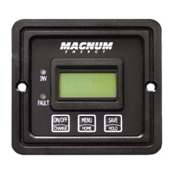
Table 6.1, Remote Troubleshooting ..........34 List of Figures Figure 1-1, Front Panel Features ............ 2 Figure 2-3, Remote Control Connections ........5 Figure 4-1, Inverter/Charger Menu Map ........18 Figure 6-1, Performing an Inverter Reset ........36 ©2009 Magnum Energy Inc. -
Page 4: Overiew
“MENU/HOME” button also serves as a “HOME” button to return directly to the “Status” menu • SAVE or HOLD Pushbutton - button serves as a “SAVE” button to save settings when in the SETUP menus The “HOLD” button stops the status screen scrolling. ©2009 Magnum Energy Inc. -
Page 5: Installation
AC power is connected to the inverter. While monitoring the front of the remote, connect the other end of the cable into the RJ11 jack on the back-side of the remote (see fi gure 2- ©2009 Magnum Energy Inc. - Page 6 Bezel using the Bezel as a template. Mark and predrill 4 1/8” holes. Mount the Bezel using the four #6 x 3/4” screws. Next mount the remote to the Bezel using the two #6 x 1/2” Phillips fl at head screws. ©2009 Magnum Energy Inc.
-
Page 7: Figure 2-3, Remote Control Connections
R J1 1 C o n n e ctio n R e m o te C a b le R E M O T E P o rt (b lu e ) Figure 2-3, Remote Control Connections ©2009 Magnum Energy Inc. -
Page 8: Setup
• Change Pushbutton - This button allows you to quickly scroll through and select various menu items and settings after pressing the menu pushbut- ton. • Save Pushbutton - This button saves the menu item displayed on the screen. A saved setting is indicated by arrow symbol. ©2009 Magnum Energy Inc. - Page 9 SHORE SHORE SHORE ....5 Amps 15 Amps 30 Amps Figure 3-1, SHORE: Shore Max Selections ©2009 Magnum Energy Inc.
- Page 10 H O L D If this setting is correct , press men u button to access different m enu item s press press press SEARCH SEARCH SEARCH ....5 Watt 20 Watt Figure 3-2, SEARCH: Search watts ©2009 Magnum Energy Inc.
-
Page 11: Table 3.1, Battery Amphrs To Absorb Charging Time
BAT AHRS BAT AHRS BAT AHRS ....200 AH 400 AH 800 AH Figure 3-3, SETUP: 03 Batt Amphrs Selections ©2009 Magnum Energy Inc. -
Page 12: Table 3.2, Battery Size To Battery Amp-Hours (Estimated)
“series string” and the amp-hour capacity doesn’t change. Each “series string” is connected together in parallel to increase the amp-hour capacity. Add the amp-hour capacity of each “series string” connected in parallel to determine the total amp-hour capacity of the battery bank. ©2009 Magnum Energy Inc. -
Page 13: Table 3.3, Battery Type To Charge Voltages
BAT TYPE BAT TYPE BAT TYPE BAT TYPE ..... Flooded AGM 1 AGM 2 Figure 3-4, SETUP: 04 Battery Type Selections ©2009 Magnum Energy Inc. - Page 14 CHG RATE CHG RATE CHG RATE ....10 % 50 % 100 % Figure 3-5, SETUP: 05 Charge Rate Selections ©2009 Magnum Energy Inc.
- Page 15 LBCO LBCO LBCO ....9 VDC 10 VDC 11 VDC Figure 3-3, LBCO: Low Battery Cut Out ©2009 Magnum Energy Inc.
- Page 16 If this setting is correct , press men u button to access different m enu item s press press press VAC DROP VAC DROP VAC DROP ....60 VAC 80 VAC 100 VAC Figure 3-7, SETUP: 06 VAC Dropout Selections ©2009 Magnum Energy Inc.
- Page 17 Warning: Only Equalize in well ventilated areas. Consult your battery manufacturer for recommendations on Equalizing batteries. Info: Equalization charging is not available if GEL or AGM 2 is selected under the SETUP: 04 Battery Type menu. ©2009 Magnum Energy Inc.
- Page 18 Info: When “Model: UNKNOWN” is displayed, the remote is not able to determine the inverter model, this is due to an older inverter model or an inverter revision newer than the remote; all remote menu selections and features that are available in the inverter will function normally. ©2009 Magnum Energy Inc.
-
Page 19: Table 3.4, Inverter/Charger Default Settings
LBCO = 10 VDC (12-volt models), 06 Low Battery Cut Out 20.0 VDC (24-volt models); or 40.0 VDC (48-volt models). 07 VAC dropout Dropout = 80VAC (150VAC for export) 08 Power Save PwrSave = On (15min) 09 Equalize Disabled ©2009 Magnum Energy Inc. -
Page 20: Menu Map: Me-Mr Remote Control
S av es s elec tion in s etup m enu H O L D H old 5 s ec onds s tops s tatus m enu s c rolling and “holds ” SAVE s c reens H O L D Figure 4-1, Inverter/Charger Menu Map ©2009 Magnum Energy Inc. -
Page 21: Operation
The top and bottom lines provides the inverter/charger status, setup menus and tech information which is detailed in this section. This display automatically powers up with the current system status on the top line and the Home Screen on the bottom line. ©2009 Magnum Energy Inc. - Page 22 Info: The ME-MR remote control is an inverter only controller. In order to display a Magnum Energy accessory you need to use the ME-RC50 remote control. Please refer to the ME-RC50 remote control manual on the Magnum Energy website at www. magnumenergy.
- Page 23 Use these status messages along with the Status LED’s to determine the inverter/charger’s current operating status and to help troubleshoot the system if a fault occurs. There are three operating modes of the inverter/charger: • Inverter Mode • Charger Mode • Fault Mode ©2009 Magnum Energy Inc.
- Page 24 Invert appears on the LCD. The INV (green) LED’s are on solid. The FAULT (red) LED is off. Invert 12.6V Figure 5-4, Inverting Mode • Invert - The inverter is providing AC voltage on its output by inverting power from the batteries. ©2009 Magnum Energy Inc.
- Page 25 04 Battery Type setting) while bulk charging. During this stage, the DC charging current decreases as the battery becomes charged. This charge stage continues until the Absorb Charging time (determined by the SETUP: 03 Battery AmpHrs setting) is fi nished. ©2009 Magnum Energy Inc.
- Page 26 4 hours “Float Charging”. This cycle helps to ensure the batteries are monitored and maintained; and continues as long as AC power is continuously connected to the AC input. ©2009 Magnum Energy Inc.
- Page 27 If in doubt, disconnect the DC loads to prevent damage. Info: Equalization charging is not available if GEL or AGM 2 is selected under the SETUP: 04 Battery Type menu. ©2009 Magnum Energy Inc.
- Page 28 34 VDC (24-volt models), or 68 VDC (48-volt models). Remedy: This fault usually only occurs when an external DC charg- ing source is charging the inverter’s battery bank. Turn off any other additional charging source to allow the DC voltage level to drop. ©2009 Magnum Energy Inc.
- Page 29 Once the AC loads are reduced or the output wiring is corrected; the inverter can be restarted after a manual restart has been accomplished. ©2009 Magnum Energy Inc.
- Page 30 AC voltage from an external AC source has been detected on the inverters AC output. When the unit shuts down because of this fault condition, an inverter reset will be required to resume operation (see section 6.2 to reset the inverter). ©2009 Magnum Energy Inc.
- Page 31 AC output or the wires are incorrectly wired. Once the AC loads are reduced or the output wiring is corrected; manually restart the inverter to resume operation. If this fault condition continues after all these recommendation, perform a inverter reset (see section 6.2). ©2009 Magnum Energy Inc.
- Page 32 Remedy - If this fault occurs while inverting, reduce load on the inverter. If it occurs while charging, turn down the Charge Rate. If it occurs often ensure the inverter has adequate ventilation and the internal cooling fans are operational. ©2009 Magnum Energy Inc.
- Page 33 (listen and make sure you hear an audible “click” from the connectors at both inverters). Info: This fault has been known to occur when a Magnum Energy accessory is plugged into the Stack Port, but the installation is not using multiple inverters in a stacked confi...
- Page 34 E R R O R! N T C S nsr Figure 5-30, Internal NTC Fault • NTC Snsr - This fault message displays and the inverter shuts down because the internal NTC (temperature sensor) circuit has been activated. ©2009 Magnum Energy Inc.
-
Page 35: Table 5.1, Led Indicator Guide
Inverter is in search mode (the AC load is below BLINKING the SETUP: 01 Search Watts setting). Normal operation. FAULT (red) A fault conditionhas been detected, check the LCD displayto fi nd and correct the cause. ©2009 Magnum Energy Inc. -
Page 36: Troubleshooting
Inverter is not Ensure inverter batteries are connected to connected and inverter is batteries. operating correctly without any AC power connected (can invert and power AC loads from batteries). ©2009 Magnum Energy Inc. - Page 37 Temperature Sensor (BTS) temperature. If the BTS is installed, the charge voltage settings will increase if the temperature around the BTS is below 77° F (25° C) and decrease if the temperature around the BTS is higher than 77° F (25° C). ©2009 Magnum Energy Inc.
-
Page 38: Figure 6-1, Performing An Inverter Reset
Info: There may be a momentary spark when the positive battery cable is connected to the inverter’s terminal; this is normal and in- dicates that the inverter’s internal capacitors are being charged. ©2009 Magnum Energy Inc. -
Page 39: Limited Warranty
3. During the limited warranty period, Magnum Energy will repair, or replace at Magnum Energy’s option, any defective parts, or any parts that will not properly operate for their intended use with factory new or rebuilt replacement items if such repair or replacement is needed because of product malfunction or failure during normal usage. - Page 40 Magnum Energy, Inc. 2211 West Casino Rd. Everett, WA 98204 Phone: 425.353.8833 Fax: 425.353.8390 Web: www.magnumenergy.com PN: 64-0031 Rev A...
Need help?
Do you have a question about the ME-MR Series and is the answer not in the manual?
Questions and answers