Xilinx Virtex-7 FPGA VC7203 Characterization Kit IBERT Getting Started Manual
Hide thumbs
Also See for Virtex-7 FPGA VC7203 Characterization Kit IBERT:
- Getting started manual (74 pages) ,
- User manual (65 pages) ,
- Getting started manual (43 pages)

Related Manuals for Xilinx Virtex-7 FPGA VC7203 Characterization Kit IBERT


Summary of Contents for Xilinx Virtex-7 FPGA VC7203 Characterization Kit IBERT
- Page 1 Virtex-7 FPGA VC7203 Characterization Kit IBERT Getting Started Guide Vivado Design Suite 2013.3 UG847 (v4.0) November 6, 2013...
-
Page 2: Revision History
(including loss of data, profits, goodwill, or any type of loss or damage suffered as a result of any action brought by a third party) even if such damage or loss was reasonably foreseeable or Xilinx had been advised of the possibility of the same. -
Page 3: Table Of Contents
Appendix A: Additional Resources Xilinx Resources ............41 Solution Centers . - Page 4 VC7203 IBERT Getting Started Guide Send Feedback UG847 (v4.0) November 6, 2013...
-
Page 5: Overview
Configuring the FPGA, page 13 Launching the Vivado Design Suite Software, page 14 Starting the SuperClock-2 Module, page 16 Viewing GTX Transceiver Operation, page 23 Closing the IBERT Demonstration, page 23 VC7203 IBERT Getting Started Guide www.xilinx.com Send Feedback UG847 (v4.0) November 6, 2013... -
Page 6: Requirements
The hardware and software required to rebuild the IBERT demonstration designs are: • Xilinx Vivado Design Suite version 2013.3 • PC with a version of the Windows operating system supported by Xilinx Vivado Design Suite Setting Up the VC7203 Board This section describes how to set up the VC7203 board. -
Page 7: Extracting The Project Files
The GTX IBERT demonstration operates one GTX Quad at a time. This section describes how to test GTX Quad 115. The remaining GTX Quads are tested following a similar series of steps. VC7203 IBERT Getting Started Guide www.xilinx.com Send Feedback UG847 (v4.0) November 6, 2013... -
Page 8: Connecting The Gtx Transceivers And Reference Clocks
Note: Figure 1-1 is for reference only and might not reflect the current revision of the board. X-Ref Target - Figure 1-1 Figure 1-1: GTX Quad Locations www.xilinx.com VC7203 IBERT Getting Started Guide Send Feedback UG847 (v4.0) November 6, 2013... - Page 9 For the GTX IBERT demonstration, the output clock frequencies are preset to 156.25 MHz. For more information regarding the SuperClock-2 module, see HW-CLK-101-SCLK2 SuperClock-2 Module User Guide (UG770). VC7203 IBERT Getting Started Guide www.xilinx.com Send Feedback UG847 (v4.0) November 6, 2013...
-
Page 10: Attach The Gtx Quad Connector
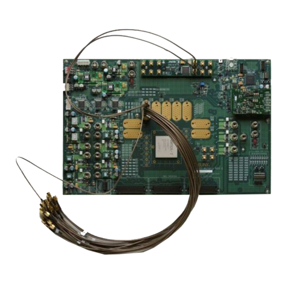
X-Ref Target - Figure 1-5 Figure 1-5: BullsEye Connector Attached to Quad 115 www.xilinx.com VC7203 IBERT Getting Started Guide Send Feedback UG847 (v4.0) November 6, 2013... -
Page 11: Gtx Transceiver Clock Connections
To ensure good connectivity, it is recommended that the adapters be secured with a wrench; however, do not over tighten the SMAs. X-Ref Target - Figure 1-6 Figure 1-6: SMA F-F Adapter VC7203 IBERT Getting Started Guide www.xilinx.com Send Feedback UG847 (v4.0) November 6, 2013... - Page 12 VC7203 board with the cable connections required for the Quad 115 GTX IBERT demonstration. X-Ref Target - Figure 1-8 Figure 1-8: Cable Connections for Quad 115 GTX IBERT Demonstration www.xilinx.com VC7203 IBERT Getting Started Guide Send Feedback UG847 (v4.0) November 6, 2013...
-
Page 13: Configuring The Fpga
Table 1-1: SD Card Contents and Configuration Addresses Demonstration ADR2 ADR1 ADR0 Design GTX Quad 113 GTX Quad 114 GTX Quad 115 GTX Quad 116 GTX Quad 117 GTX Quad 118 VC7203 IBERT Getting Started Guide www.xilinx.com Send Feedback UG847 (v4.0) November 6, 2013... -
Page 14: Launching The Vivado Design Suite Software
Start Vivado Design Suite on the host computer and click Flow > Open Hardware Manager (highlighted in Figure 1-10). X-Ref Target - Figure 1-10 Figure 1-10: Vivado Design Suite, Open Hardware Manager www.xilinx.com VC7203 IBERT Getting Started Guide Send Feedback UG847 (v4.0) November 6, 2013... - Page 15 An Open Hardware Target wizard pops up. Click Next on the first window. In the Vivado CSE Server Name window, make sure localhost:60001 is entered for the Server name. Click Next and it opens the server to connect to the Xilinx TCF agent. VC7203 IBERT Getting Started Guide www.xilinx.com...
-
Page 16: Starting The Superclock-2 Module
SuperClock-2 module. The SuperClock-2 module features two clock-source components: 1) An always-on Si570 crystal oscillator and, 2) an Si5368 jitter-attenuating clock multiplier. Outputs from either device can be used to drive the transceiver reference clocks. www.xilinx.com VC7203 IBERT Getting Started Guide Send Feedback... - Page 17 Properties window, enter the file path to the Probes file associated with the Q115 IBERT design (vc7203_q115.ltx) (Figure 1-13). X-Ref Target - Figure 1-13 Figure 1-13: Adding the Probes File VC7203 IBERT Getting Started Guide www.xilinx.com Send Feedback UG847 (v4.0) November 6, 2013...
- Page 18 Chapter 1: VC7203 IBERT Getting Started Guide In the Hardware window, right-click XC7VX485T_1 and select Refresh Device (Figure 1-14). X-Ref Target - Figure 1-14 Figure 1-14: Refresh Device www.xilinx.com VC7203 IBERT Getting Started Guide Send Feedback UG847 (v4.0) November 6, 2013...
- Page 19 X-Ref Target - Figure 1-15 Figure 1-15: Run Tcl Script... To view the SuperClock 2 settings in the VIO core, select the following signals: u_scm2/u_vio_sclk2_control/si570_start u_scm2/u_vio_sclk2_control/si570_addr[6:0] u_scm2/u_vio_sclk2_control/si5368_start u_scm2/u_vio_sclk2_control/si5368_addr[6:0] VC7203 IBERT Getting Started Guide www.xilinx.com Send Feedback UG847 (v4.0) November 6, 2013...
- Page 20 ROM address changes the reference clock(s) frequency. The complete list of pre-programmed SuperClock-2 frequencies and their associated ROM addresses is provided in Table 1-2, page X-Ref Target - Figure 1-16 Figure 1-16: SuperClock-2 Module VIO Core www.xilinx.com VC7203 IBERT Getting Started Guide Send Feedback UG847 (v4.0) November 6, 2013...
- Page 21 Add (+) button. For this project, connect the following links: MGT_X1Y8/TX to MGT_X1Y8/RX MGT_X1Y9/TX to MGT_X1Y9/RX MGT_X1Y10/TX to MGT_X1Y10/RX MGT_X1Y11/TX to MGT_X1Y11/RX VC7203 IBERT Getting Started Guide www.xilinx.com Send Feedback UG847 (v4.0) November 6, 2013...
- Page 22 Chapter 1: VC7203 IBERT Getting Started Guide This is shown in Figure 1-18. X-Ref Target - Figure 1-18 Figure 1-18: Create Links Window www.xilinx.com VC7203 IBERT Getting Started Guide Send Feedback UG847 (v4.0) November 6, 2013...
-
Page 23: Viewing Gtx Transceiver Operation
Closing the IBERT Demonstration To stop the IBERT demonstration: Close the Vivado Design Suite application by selecting File > Exit. Place the main power switch SW1 in the off position. VC7203 IBERT Getting Started Guide www.xilinx.com Send Feedback UG847 (v4.0) November 6, 2013... -
Page 24: Superclock-2 Frequency Table
334.125 Generic 285.000 OBSAI 76.800 SMPTE435M 668.250 Generic 290.000 OBSAI 153.600 XAUI 78.125 Generic 295.000 Generic 300.000 Generic 365.000 Generic 430.000 Generic 305.000 Generic 370.000 Generic 435.000 www.xilinx.com VC7203 IBERT Getting Started Guide Send Feedback UG847 (v4.0) November 6, 2013... -
Page 25: Creating The Gtx Ibert Core
For more details on generating IBERT cores, refer to Vivado Design Suite User Guide: Programming and Debugging (UG908). Start the Vivado Design Suite. VC7203 IBERT Getting Started Guide www.xilinx.com Send Feedback UG847 (v4.0) November 6, 2013... - Page 26 X-Ref Target - Figure 1-20 Figure 1-20: Initial Window, Vivado Design Suite When the Create a New Customized IP Location dialog window opens (not shown), click Next. www.xilinx.com VC7203 IBERT Getting Started Guide Send Feedback UG847 (v4.0) November 6, 2013...
- Page 27 Figure 1-21: Select Device Back on the Manage IP Settings window, select Verilog for Target language, Vivado Simulator for Target simulator, Mixed for Simulator language, and a directory to save VC7203 IBERT Getting Started Guide www.xilinx.com Send Feedback UG847 (v4.0) November 6, 2013...
- Page 28 Chapter 1: VC7203 IBERT Getting Started Guide the customized IP (Figure 1-22). Click Finish. X-Ref Target - Figure 1-22 Figure 1-22: Manage IP Settings www.xilinx.com VC7203 IBERT Getting Started Guide Send Feedback UG847 (v4.0) November 6, 2013...
- Page 29 In the Vivado IP Catalog window, open the Debug & Verification folder, then open the Debug folder, and double-click IBERT 7 Series GTX (Figure 1-23). X-Ref Target - Figure 1-23 Figure 1-23: IP Catalog VC7203 IBERT Getting Started Guide www.xilinx.com Send Feedback UG847 (v4.0) November 6, 2013...
- Page 30 LineRate (Gbps) to 12.5, then use the drop-down to change the Refclk (MHz) to 156.250. Do not change the other defaults (Figure 1-24). X-Ref Target - Figure 1-24 Figure 1-24: Customize IP - Protocol Definition www.xilinx.com VC7203 IBERT Getting Started Guide Send Feedback UG847 (v4.0) November 6, 2013...
- Page 31 Protocol Selected next to QUAD_113, and select MGTREFCLK1 113 in the Refclk Selection drop-down menu (Figure 1-25). X-Ref Target - Figure 1-25 Figure 1-25: Customize IP - Protocol Selection VC7203 IBERT Getting Started Guide www.xilinx.com Send Feedback UG847 (v4.0) November 6, 2013...
- Page 32 1-26). Press OK. A Generate Output Products window opens. Leave the defaults unchanged, and press Generate. X-Ref Target - Figure 1-26 Figure 1-26: Customize IP - Clock Settings www.xilinx.com VC7203 IBERT Getting Started Guide Send Feedback UG847 (v4.0) November 6, 2013...
- Page 33 1-27). Specify a location to save the design, press OK, and the design opens in a new Vivado design tools window. X-Ref Target - Figure 1-27 Figure 1-27: Open IP Example Design VC7203 IBERT Getting Started Guide www.xilinx.com Send Feedback UG847 (v4.0) November 6, 2013...
- Page 34 Add the top level ports from top_scm2.v to the module declaration and instantiate the top_scm2 module in the example ibert wrapper (Figure 1-29). Click File > Save File. www.xilinx.com VC7203 IBERT Getting Started Guide Send Feedback UG847 (v4.0) November 6, 2013...
- Page 35 Creating the GTX IBERT Core X-Ref Target - Figure 1-29 Figure 1-29: SuperClock-2 in the Example IBERT Wrapper VC7203 IBERT Getting Started Guide www.xilinx.com Send Feedback UG847 (v4.0) November 6, 2013...
- Page 36 IBERT design (Figure 1-30). X-Ref Target - Figure 1-30 Figure 1-30: Design Sources File Hierarchy 14. Click Run Synthesis in the Flow Navigator, which synthesizes the design. www.xilinx.com VC7203 IBERT Getting Started Guide Send Feedback UG847 (v4.0) November 6, 2013...
- Page 37 15. When synthesis is done, a Synthesis Complete window pops up. Select Open Synthesized Design and click OK (Figure 1-31). X-Ref Target - Figure 1-31 Figure 1-31: Synthesis Completed VC7203 IBERT Getting Started Guide www.xilinx.com Send Feedback UG847 (v4.0) November 6, 2013...
- Page 38 Debug Core Options tab in the Cell Properties window and change C_USER_SCAN_CHAIN* to 2 (Figure 1-32). Click File > Save Constraints. X-Ref Target - Figure 1-32 Figure 1-32: Debug Core Options for dbg_hub www.xilinx.com VC7203 IBERT Getting Started Guide Send Feedback UG847 (v4.0) November 6, 2013...
- Page 39 Yes. X-Ref Target - Figure 1-33 Figure 1-33: Generate Bitstream 18. When implementation completes, navigate to the project directory and locate the resultant bitstream here: \ibert_7series_gtx_0\example_project\ibert_7series_gtx_0_exampl e\ibert_7series_gtx_0_example.runs\impl_1\. VC7203 IBERT Getting Started Guide www.xilinx.com Send Feedback UG847 (v4.0) November 6, 2013...
- Page 40 Chapter 1: VC7203 IBERT Getting Started Guide www.xilinx.com VC7203 IBERT Getting Started Guide Send Feedback UG847 (v4.0) November 6, 2013...
-
Page 41: Appendix A: Additional Resources
Virtex-7 FPGA VC7203 Characterization Kit documentation Virtex-7 FPGA VC7203 Characterization Master Answer Record (AR 52383) These Xilinx documents and sites provide supplemental material useful with this guide: UG957, VC7203 Virtex-7 FPGA GTX Transceiver Characterization Board User Guide UG770, HW-CLK-101-SCLK2 SuperClock-2 Module User Guide... - Page 42 Appendix A: Additional Resources www.xilinx.com VC7203 IBERT Getting Started Guide Send Feedback UG847 (v4.0) November 6, 2013...
-
Page 43: Appendix B: Warranty
For any breach by Xilinx of this limited warranty, the exclusive remedy of Customer and the sole liability of Xilinx shall be, at the option of Xilinx, to replace or repair the affected products, or to refund to Customer the price of the affected products. The availability of replacement products is subject to product discontinuation policies at Xilinx. - Page 44 Appendix B: Warranty www.xilinx.com VC7203 IBERT Getting Started Guide Send Feedback UG847 (v4.0) November 6, 2013...
Need help?
Do you have a question about the Virtex-7 FPGA VC7203 Characterization Kit IBERT and is the answer not in the manual?
Questions and answers