Xilinx Virtex-7 FPGA VC7215 Getting Started Manual
Characterization kit ibert
Hide thumbs
Also See for Virtex-7 FPGA VC7215:
- Getting started manual (74 pages) ,
- User manual (65 pages) ,
- Getting started manual (44 pages)

Related Manuals for Xilinx Virtex-7 FPGA VC7215


Summary of Contents for Xilinx Virtex-7 FPGA VC7215
- Page 1 Virtex-7 FPGA VC7215 Characterization Kit IBERT Getting Started Guide Vivado Design Suite 2014.4 UG970 (v7.0) November 24, 2014...
-
Page 2: Revision History
Xilinx’s limited warranty, please refer to Xilinx’s Terms of Sale which can be viewed at www.xilinx.com/legal.htm#tos; IP cores may be subject to warranty and support terms contained in a license issued to you by Xilinx. Xilinx products are not designed or intended to be fail-safe or for use in any application requiring fail-safe performance;... -
Page 3: Table Of Contents
Appendix A: Additional Resources Xilinx Resources ............41 Solution Centers . - Page 4 VC7215 Getting Started Guide UG970 (v7.0) November 24, 2014...
-
Page 5: Overview
Two GTH transceiver power supply modules (installed on board) • SuperClock-2 module, Rev 1.0 (installed on board) • 12V DC power adapter • USB cable, standard-A plug to Micro-B plug VC7215 Getting Started Guide www.xilinx.com Send Feedback UG970 (v7.0) November 24, 2014... -
Page 6: Setting Up The Vc7215 Board
CONTROL VOLTAGE header, J18, and place another jumper across Si570 INH header J11. d. Screw down a 50Ω SMA terminator onto each of the six unused Si5368 clock output SMA connectors: J7, J8, J12, J15, J16 and J17. www.xilinx.com VC7215 Getting Started Guide Send Feedback UG970 (v7.0) November 24, 2014... -
Page 7: Extracting The Project Files
The Vivado project files required to run the IBERT demonstrations are located in rdf0294-vc7215-ibert-2014-4.zip on the SD card provided with the VC7215 board. They are also available online at the Virtex-7 FPGA VC7215 Characterization Kit website. The ZIP file contains these files: •... -
Page 8: Running The Gth Ibert Demonstration
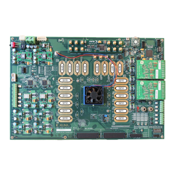
GTH transceiver Quads on the VC7215 board. Note: Figure 1-1 is for reference only and might not reflect the current revision of the board. X-Ref Target - Figure 1-1 Figure 1-1: GTH Quad Locations www.xilinx.com VC7215 Getting Started Guide Send Feedback UG970 (v7.0) November 24, 2014... - Page 9 For the GTH IBERT demonstration, the output clock frequencies are preset to 325.00 MHz. For more information regarding the SuperClock-2 module, refer to HW-CLK-101-SCLK2 SuperClock-2 Module User Guide (UG770) [Ref VC7215 Getting Started Guide www.xilinx.com Send Feedback UG970 (v7.0) November 24, 2014...
-
Page 10: Attach The Gth Quad Connector
Hold the connector flush with the board and fasten it by tightening the two captive screws. X-Ref Target - Figure 1-5 Figure 1-5: BullsEye Connector Attached to Quad 115 www.xilinx.com VC7215 Getting Started Guide Send Feedback UG970 (v7.0) November 24, 2014... -
Page 11: Gth Transceiver Clock Connections
SMAs. X-Ref Target - Figure 1-6 Figure 1-6: SMA F-F Adapter X-Ref Target - Figure 1-7 Figure 1-7: TX-To-RX Loopback Connection Example VC7215 Getting Started Guide www.xilinx.com Send Feedback UG970 (v7.0) November 24, 2014... - Page 12 VC7215 board with the cable connections required for the Quad 115 GTH IBERT demonstration. X-Ref Target - Figure 1-8 Figure 1-8: Cable Connections for Quad 115 GTH IBERT Demonstration www.xilinx.com VC7215 Getting Started Guide Send Feedback UG970 (v7.0) November 24, 2014...
-
Page 13: Configuring The Fpga
The FPGA can also be configured through Vivado Design Suite using the .bit files available on the SC card or online (as collection rdf0294-vc7215-ibert-2014-4.zip) at the Virtex-7 FPGA VC7215 Characterization Kit website. To configure from the SD card: Insert the SD card labeled IBERT #1 provided with the VC7215 board into the SD card reader slot located on the bottom side (upper right corner) of the VC7215 board. - Page 14 GTH Quad 216 GTH Quad 217 GTH Quad 218 GTH Quad 219 IBERT #3 USB/UART LED Scroll Pushbuttons DIP Switches Place the main power switch SW1 to the ON position. www.xilinx.com VC7215 Getting Started Guide Send Feedback UG970 (v7.0) November 24, 2014...
-
Page 15: Setting Up Vivado Design Suite
Start Vivado Design Suite on the host computer and click Flow > Open Hardware Manager (shown in Figure 1-10 X-Ref Target - Figure 1-10 Figure 1-10: Vivado Design Suite, Open Hardware Manager VC7215 Getting Started Guide www.xilinx.com Send Feedback UG970 (v7.0) November 24, 2014... - Page 16 An Open Hardware Target wizard pops up. Click Next on the first window. In the Hardware Server Settings window, select Local server (target is on local machine). Click Next to open the server and connect to the Xilinx TCF JTAG cable.
- Page 17 X-Ref Target - Figure 1-12 Figure 1-12: Select Hardware Target In the Open Hardware Target Summary window, click Finish. The wizard closes and the Vivado Design Suite opens the hardware target. VC7215 Getting Started Guide www.xilinx.com Send Feedback UG970 (v7.0) November 24, 2014...
-
Page 18: Starting The Superclock-2 Module
In the Hardware Device Properties window, enter the file path to the Q115 probes file (vc7215_ibert_q115_debug_nets.ltx) in the extracted IBERT files from the SD card (Figure 1-13). X-Ref Target - Figure 1-13 Figure 1-13: Adding the Probes File www.xilinx.com VC7215 Getting Started Guide Send Feedback UG970 (v7.0) November 24, 2014... - Page 19 If the FPGA was not programmed using the SD card, provide both the programming and the probes files, and select Program Device. X-Ref Target - Figure 1-14 Figure 1-14: Refresh/Program Device VC7215 Getting Started Guide www.xilinx.com Send Feedback UG970 (v7.0) November 24, 2014...
- Page 20 1-15). In the following Run Script window, navigate to the setup_scm2_325_00.tcl script in the extracted files and click OK. X-Ref Target - Figure 1-15 Figure 1-15: Run Tcl Script www.xilinx.com VC7215 Getting Started Guide Send Feedback UG970 (v7.0) November 24, 2014...
- Page 21 ROM address changes the reference clock(s) frequency. The complete list of pre-programmed SuperClock-2 frequencies and their associated ROM addresses is provided in Table 1-2, page X-Ref Target - Figure 1-16 Figure 1-16: SuperClock-2 Module VIO Core VC7215 Getting Started Guide www.xilinx.com Send Feedback UG970 (v7.0) November 24, 2014...
- Page 22 Links window by right-clicking and selecting Create Links, or by clicking the Create Links button (Figure 1-17). X-Ref Target - Figure 1-17 Figure 1-17: Serial I/O Analyzer - Create Links... www.xilinx.com VC7215 Getting Started Guide Send Feedback UG970 (v7.0) November 24, 2014...
- Page 23 MGT_X1Y20/TX to MGT_X1Y20/RX MGT_X1Y21/TX to MGT_X1Y21/RX MGT_X1Y22/TX to MGT_X1Y22/RX MGT_X1Y23/TX to MGT_X1Y23/RX This linking is shown in Figure 1-18. X-Ref Target - Figure 1-18 Figure 1-18: Create Links Window VC7215 Getting Started Guide www.xilinx.com Send Feedback UG970 (v7.0) November 24, 2014...
-
Page 24: Viewing Gth Transceiver Operation
Increase the TX differential swing of the transceiver (to compensate for any loss due to PCB process variation). • Click the respective TX Reset button followed by BERT Reset. www.xilinx.com VC7215 Getting Started Guide Send Feedback UG970 (v7.0) November 24, 2014... -
Page 25: Closing The Ibert Demonstration
62.500 SATA 75.000 Generic 240.000 GigE 125.000 SATA 150.000 Generic 245.000 GigE 250.000 SATA 300.000 Generic 250.000 GigE 500.000 SATA 600.000 Generic 255.000 GPON 187.500 74.250 Generic 260.000 VC7215 Getting Started Guide www.xilinx.com Send Feedback UG970 (v7.0) November 24, 2014... - Page 26 Generic 340.000 Generic 405.000 Generic 470.000 Generic 345.000 Generic 410.000 Generic 475.000 Generic 350.000 Generic 415.000 Generic 480.000 Generic 355.000 Generic 420.000 Generic 485.000 Generic 360.000 Generic 425.000 www.xilinx.com VC7215 Getting Started Guide Send Feedback UG970 (v7.0) November 24, 2014...
-
Page 27: Creating The Gth Ibert Core
New IP Location. X-Ref Target - Figure 1-20 Figure 1-20: Initial Window, Vivado Design Suite When the Create a New Customized IP Location dialog box opens (not shown), click Next. VC7215 Getting Started Guide www.xilinx.com Send Feedback UG970 (v7.0) November 24, 2014... - Page 28 Part field. A Select Device window pops up. Use the drop-down menu items to narrow the choices. Select the xc7vx690tffg1927-3 device (Figure 1-21). Click OK. X-Ref Target - Figure 1-21 Figure 1-21: Select Device www.xilinx.com VC7215 Getting Started Guide Send Feedback UG970 (v7.0) November 24, 2014...
- Page 29 IP (Figure 1-22). Click Finish. Note: Make sure the directory name does not include spaces. X-Ref Target - Figure 1-22 Figure 1-22: Manage IP Settings VC7215 Getting Started Guide www.xilinx.com Send Feedback UG970 (v7.0) November 24, 2014...
- Page 30 Next, in the IP Catalog window, open the Debug & Verification folder, then open the Debug folder, and double-click IBERT 7 Series GTH (Figure 1-23). X-Ref Target - Figure 1-23 Figure 1-23: IP Catalog www.xilinx.com VC7215 Getting Started Guide Send Feedback UG970 (v7.0) November 24, 2014...
- Page 31 LineRate (Gbps) to 13.0. Then use the drop-down menu to change the Refclk (MHz) to 325.00. Keep the defaults for other fields (Figure 1-24). X-Ref Target - Figure 1-24 Figure 1-24: Customize IP - Protocol Definition VC7215 Getting Started Guide www.xilinx.com Send Feedback UG970 (v7.0) November 24, 2014...
- Page 32 In the Protocol Selection tab, use the Protocol Selected drop-down menu next to QUAD_115 to select Custom 1 / 13.0 Gbps (Figure 1-25). X-Ref Target - Figure 1-25 Figure 1-25: Customize IP - Protocol Selection www.xilinx.com VC7215 Getting Started Guide Send Feedback UG970 (v7.0) November 24, 2014...
- Page 33 Package Pin and J26 for N Package Pin (the FPGA pins that the system clock connects to), and ensure the Frequency is set to 200.00 (Figure 1-26). Press OK. X-Ref Target - Figure 1-26 Figure 1-26: Customize IP - Clock Settings VC7215 Getting Started Guide www.xilinx.com Send Feedback UG970 (v7.0) November 24, 2014...
- Page 34 OK, A Generate Output Products window opens. Leave the defaults unchanged, and press Generate. The design opens in a new Vivado window. X-Ref Target - Figure 1-27 Figure 1-27: Open IP Example Design www.xilinx.com VC7215 Getting Started Guide Send Feedback UG970 (v7.0) November 24, 2014...
- Page 35 OK. The SuperClock-2 Module Design Sources and Constraints are automatically added to the example design (Figure 1-28). X-Ref Target - Figure 1-28 Figure 1-28: Sources after Running add_scm2.tcl VC7215 Getting Started Guide www.xilinx.com Send Feedback UG970 (v7.0) November 24, 2014...
- Page 36 (Figure 1-29). Click File > Save File. X-Ref Target - Figure 1-29 Figure 1-29: SuperClock-2 in the Example IBERT Wrapper www.xilinx.com VC7215 Getting Started Guide Send Feedback UG970 (v7.0) November 24, 2014...
- Page 37 13. In the Sources window, Design Sources should now reflect that the SuperClock-2 module is part of the example IBERT design (Figure 1-30). X-Ref Target - Figure 1-30 Figure 1-30: Design Sources File Hierarchy VC7215 Getting Started Guide www.xilinx.com Send Feedback UG970 (v7.0) November 24, 2014...
- Page 38 15. When synthesis is done, a Synthesis Complete window pops up. Select Open Synthesized Design and click OK (Figure 1-32). X-Ref Target - Figure 1-32 Figure 1-32: Synthesis Completed www.xilinx.com VC7215 Getting Started Guide Send Feedback UG970 (v7.0) November 24, 2014...
- Page 39 Debug Core Options tab in the Cell Properties window. Change C_USER_SCAN_CHAIN* to 3 (Figure 1-33). Click File > Save Constraints. X-Ref Target - Figure 1-33 Figure 1-33: Debug Core Options for dbg_hub VC7215 Getting Started Guide www.xilinx.com Send Feedback UG970 (v7.0) November 24, 2014...
- Page 40 18. When the Bitstream Generation Completed dialog window appears, click Cancel (Figure 1-35). X-Ref Target - Figure 1-35 Figure 1-35: Bitstream Generation Completed 19. The generated bitstream can be found in the following directory: ..\ibert_7series_gth_0\ibert_7series_gth_0_example\ibert_7serie s_gth_0_example.runs\impl_1 www.xilinx.com VC7215 Getting Started Guide Send Feedback UG970 (v7.0) November 24, 2014...
-
Page 41: Appendix A: Additional Resources
Virtex-7 FPGA VC7215 Characterization Kit Virtex-7 FPGA VC7215 Characterization Kit documentation Virtex-7 FPGA VC7215 Characterization Kit Master Answer Record (AR 55180) These Xilinx documents provide supplemental material useful with this guide: VC7215 Virtex-7 FPGA GTH Transceiver Characterization Board User Guide (UG972) - Page 42 Appendix A: Additional Resources www.xilinx.com VC7215 Getting Started Guide Send Feedback UG970 (v7.0) November 24, 2014...
-
Page 43: Appendix B: Warranty
For any breach by Xilinx of this limited warranty, the exclusive remedy of Customer and the sole liability of Xilinx shall be, at the option of Xilinx, to replace or repair the affected products, or to refund to Customer the price of the affected products. The availability of replacement products is subject to product discontinuation policies at Xilinx. - Page 44 Appendix B: Warranty www.xilinx.com VC7215 Getting Started Guide Send Feedback UG970 (v7.0) November 24, 2014...
Need help?
Do you have a question about the Virtex-7 FPGA VC7215 and is the answer not in the manual?
Questions and answers