Table of Contents
Advertisement
Quick Links
Advertisement
Table of Contents

Related Manuals for Martin Audio MLA


Summary of Contents for Martin Audio MLA
- Page 1 Multi-cellular Loudspeaker Array User Guide...
-
Page 2: Table Of Contents
MLA System USER GUIDE Contents Introduction ..................................15 About This Manual ................................15 Important Safety Instructions ............................... 16 MLA/MLD MLA Compact ..............................16 Merlin ....................................16 Electrical Compliance ................................17 Unpacking the Units ................................17 MLA ...................................... 18 Mechanical Design................................19 Rigging .................................... - Page 3 Rated Power (2) ................................41 Dispersion ..................................41 Crossover Frequencies ..............................41 Audio input ................................... 41 Network ..................................41 Amplifier Module ................................41 Power Supply ................................41 General ..................................42 Accessories ..................................42 Notes ..................................... 42 MLA System User Guide V2.1...
- Page 4 Notes ..................................... 60 MLA Compact ..................................61 Mechanical Design................................62 Rigging ....................................62 Acoustic Design ................................. 64 Low Frequency ................................64 Mid-Range ..................................66 High Frequency ................................67 FIR Crossovers ................................68 Amplifier module ................................69 MLA System User Guide V2.1...
- Page 5 Mechanical Design................................77 Flying Upgrade ................................. 78 Rigging ....................................78 Acoustic Design ................................. 80 Amplifier module ................................80 Connections ..................................80 Mains .................................... 81 Audio & network ................................82 Essential Maintenance ..............................83 Tools Required ................................83 MLA System User Guide V2.1...
- Page 6 Audio Inputs .................................. 89 Audio Outputs ................................89 USB ....................................89 Processing Functions ................................ 89 Menu Tree ..................................91 Main....................................91 Inputs .................................... 91 Outputs ..................................91 System Setup ..................................92 Network Settings ................................92 Specifications ..................................94 MLA System User Guide V2.1...
- Page 7 Files & Utilities ................................106 Power Settings .bat file ............................... 106 Matlab Components ..............................106 Java Runtime ................................106 Martin Audio Software Backup ........................... 106 Network Information ..............................106 Picostation Configuration ............................106 Standard Configuration .............................. 106 Manually Configuring the Wireless Access Point (WAP) ..................... 108...
- Page 8 Calibration ..................................118 Battery Replacement ..............................121 MLA Compact Flying Grid ..............................123 Calibration ..................................123 MLA to MLA Compact Transition Grid ..........................124 Mains Distro- High Voltage ..............................125 Distro Mk1 ..................................125 Distro Mk2 ..................................125 Mains Distro Low Voltage ..............................126 Flightcases ..................................
- Page 9 Mk1 MLA Grid Case ..............................131 Mk2 MLA Grid Case ..............................131 Mk3 Grid Case ................................132 Mk1 MLA Compact Flying Frame Case ........................133 Mk2 MLA Compact Flying Frame Case ........................133 Tablet PC Case ................................134 Mk1 Tablet PC Case ..............................134 Mk2 Tablet PC Case ..............................
- Page 10 Air Absorption ................................202 Goals ................................... 202 Optimise EQ’s ................................204 View the SPL ................................... 205 Individual Graph Windows ............................. 207 Adding additional arrays ..............................211 Deleting an array ................................ 211 Exporting the Optimisation..............................212 MLA System User Guide V2.1...
- Page 11 Help ..................................... 223 Tool bar ..................................225 Project Workspace ..............................227 Working Offline ................................232 Adding Merlin, MLA, MLD and MLX ........................... 232 Adding MLA Compact & DSX ............................233 Adding MLA Mini ................................ 234 Adding DD12 ................................237 Adding PSX .................................. 237 Arranging the Array components ..........................
- Page 12 Block PEQ ..................................290 Sub Array/Block Ganging ............................291 MLA Mini ..................................292 MLA Mini Cell check ..............................292 Assigning Zones in MLA Mini ............................293 MLA Mini PEQ ................................296 MLA Mini Ganging ..............................298 Array Ganging ................................298 Zone Ganging ................................
- Page 13 Starting a Firmware Update............................381 MLA/MLD Conversion Tool ............................385 MLA Pick Load spreadsheet ..............................388 Ground Stacking ................................. 391 MLA Compact Pick Load Spreadsheet ..........................394 Ground Stacking ................................. 396 System Wiring ..................................398 Mains ....................................398 U-Net ....................................399 Ethernet ..................................
- Page 14 MLA System USER GUIDE MLA Flown under MLX ..............................432 Ground Stacked MLA arrays ............................434 Rigging MLA Compact ................................ 439 Ground Stacking MLA Compact ............................449 MLA System User Guide V2.1...
-
Page 15: Introduction
This manual explains in detail the individual components that comprise a complete system which may be MLA, MLA Compact, MLA Mini or even a combination of all three. System wiring and rigging is explained and the two key software packages are covered. -
Page 16: Important Safety Instructions
Only use attachments / accessories specified by Martin Audio. Use only with wheelboard and rigging hardware specified by Martin Audio. When moving the MLA using the supplied wheelboard, caution should be used to avoid injury from the cabinet tipping over. -
Page 17: Electrical Compliance
Please retain all packaging in case you need to return the unit. Please think of our environment. When the product has reached the end of its useful life, please dispose of it responsibly through a recycling centre. MLA System User Guide V2.1... -
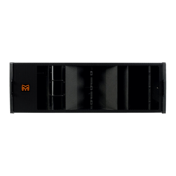
Page 18: Mla
USER GUIDE The MLA is a three-way active Multicellular loudspeaker with each cell comprising of a drive unit, a Class D high power, high efficiency amplifier and comprehensive digital signal processing. There are six cells in total, three high frequency, two mid and a low frequency cell comprising of a pair of 12"bass drivers. -
Page 19: Mechanical Design
Mechanical Design MLA Is designed mechanically to be an easy to handle, quick to rig, safe, rugged and stable touring loudspeaker. The cabinet is constructed predominantly from high grade 18mm birch plywood with rigging fabricated from powder coated steel and with decorative rubber end panels which also give improved stability when stacking on end. - Page 20 The pin MUST be repositioned until it is securely locked in place. The MLA has an improved front rigging bracket with a bar that runs the full height of the cabinet. This prevents the cabinets collapsing down on each other where there is more weight supported on the rear point; although this may only make a difference...
- Page 21 The rear bracket also has a parked position with the pin in a central hole which retains the linking bar when in transit One issue with previous Martin Audio rigging system was the difficulty experienced flicking the rear linking bar out of its parked position.
-
Page 22: Acoustic Design
- both on and off-axis. In contrast to systems which utilise direct radiators for the lows and mids, MLA’s all-horn design ensures that lows and mids are able to keep up with the very high efficiency HF section. MLA deliberately avoids the use of coaxial, co-entrant or cross-firing midrange/HF driver arrangements which introduce acoustic discontinuities that affect the on and off-axis frequency response of both mid and HF sections. -
Page 23: Mid-Range
MLA System USER GUIDE With an efficiency of 104dB @ 1m/2.83V, MLA’s Dual Hybrid® LF section has a big advantage. This is 6dB more than 98dB figure typical of a direct radiator design. MLA’s LF section utilises 2 x 12"(305mm)/3"(75mm) voice coil, neodymium drive units in Martin Audio’s trademark Hybrid low frequency horn configuration. - Page 24 MLA System USER GUIDE Another feature of MLA’s midrange horn is the HiBlade™ device, which modifies the wave-propagation in the horn throat. MLA System User Guide V2.1...
-
Page 25: High Frequency
* US Patent 6950530 High Frequency MLA’s HF section utilises 3 x 1"(25mm) exit neodymium compression drivers which feed separate, diffraction slot horns for true 90° horizontal constant directivity. In the vertical plane, MLA makes significant advances over previous thinking by adopting new vertical wavefront criteria. - Page 26 BEM models of a conventional horn show that the waveform expands as its travels down the horn to produce a convex vertical wavefront which would generally be too curved for an ideal array element. Placing a kite shaped “wedge"part-way down the horn* introduces a concavity in the waveform which compensates for this. MLA System User Guide V2.1...
-
Page 27: Fir Crossovers
FIR Crossovers Like all three-way systems, MLA’s low, mid and high frequency sections are combined by a crossover. Up to now, Linkwitz-Riley, 4th order filters have been the industry standard. With traditional filters like these, overlap at crossover can result in a non- symmetrical horizontal polar pattern if the devices being crossed-over are side by side. -
Page 28: Amplifier Module
Each MLA is fitted with a 6-channel amplifier module. Its Class D circuitry delivers a total of 3kW continuous and 6kW peak output, whilst producing significantly less heat than a linear output stage design. All channels share the same circuit topology and are driven from the same power supply. -
Page 29: Connections
Velcro. To fold the cowl flat, the straps are again used to pull the supporting triangles down left and right. MLA System User Guide V2.1... -
Page 30: Mains
Mains The MLA mains inlet is located on the rear of the cabinet and is a standard 16A Male 230V single phase IP44 rated Ceeform inlet connector. A comprehensive mains distribution system is supplied with the MLA systems which features female outlets rated at IP67. -
Page 31: Audio & Network
USER GUIDE The MLA has a universal PSU suitable for direct connection to virtually any mains voltage anywhere in the world. If you are not using the Martin Audio MLA distribution system a matching Ceeform 16A female outlet connector must be used. For outdoor use this should be rated at IP67, this is to ensure safe operating when any connectors are disconnected in damp conditions. -
Page 32: Block Diagram
Pin 3 -, Cold, out of phase. The signal source used to feed the MLA array must have line drive capabilities suitable for driving the combined load of the entire array. AES/EBU output connections are identical to analogue but cable used must be a dedicated 110Ω, low capacitance digital cable such as Belden 1800F or 1696A. -
Page 33: Essential Maintenance
Replacing the amplifier module There is no need to remove a cabinet from an array to replace a module if you can safely access the rear of the MLA speaker, the module can be replaced in situ. Disconnect all power, audio and network connections from the module. Undo all M5 Countersunk screws holding the rain cowl assembly with the appropriate size hex head driver. -
Page 34: Replacing A Compression Driver
110Ohms balanced, Receive and transmit termination Network CONNECTORS 2x IP68 rated 8-way, quick-release type PROTOCOL Unet Amplifier Module TYPE Six channel switch mode, fixed frequency PEAK OUTPUT POWER 4000W AVERAGE EFFICIENCY COOLING 4 x temperature controlled internal fans MLA System User Guide V2.1... -
Page 35: Power Supply
(1) Measured on-axis in open (4 ) space at 4 metres, then referred to 1 metre. (2) AES Standard ANSI S4.26-1984. (3) Measured in half-space at 1 metre with a tone burst signal, then referred back to open (4 ) space. (4) Calculated from 4m 2.83v sensitivity, referred to 1m. MLA System User Guide V2.1... -
Page 36: Mld
The rear bracket is slightly shorter than the MLA as the cabinet is not as tall at the back; it has a more exaggerated trapezoidal shape as a result of the greater vertical coverage angle. -
Page 37: Acoustic Design
USER GUIDE The rear bracket swings up as the MLA to join to an array but links to one position to give an angle of 13.75⁰. There is only a single hole in the bottom of the bracket to accommodate a second MLD in the array which will give a fixed angle between the two of 20⁰. -
Page 38: Connections
The mains inlet to the MLD in common with all larger format MLA series enclosures is a 16A male 230V Ceeform inlet connector. As the MLD is always going to be at the bottom of an array and will always be at 13.75⁰ to the MLA cabinet above it in an array which may already have a steep curve, the mains inlet may be angled upwards making ingress of water a possibility where systems are deployed outdoors. -
Page 39: Audio & Network
Audio & network The main connection panel is on the rear of the cabinet to the right and is identical to all MLA enclosures featuring a male input and female link 3 pin XLR for balanced analogue or AES/EBU digital input signals. Input type is selected via the Vu-Net software. -
Page 40: Essential Maintenance
Pin 3 -, Cold, out of phase. The signal source used to feed the MLA array must have line drive capabilities suitable for driving the combined load of the entire array. AES/EBU output connections are identical to analogue but cable used must be a dedicated 110Ω, low capacitance digital cable such as Belden 1800F or 1696A. -
Page 41: Specifications
1 x temperature controlled external fan MAXIMUM AMBIENT TEMPERATURE 45°C (113°F) for full output Power Supply TYPE Switch mode, fixed frequency with PFC AC INPUT OPERATING RANGE 100 – 240V ~ AC, 50 - 60Hz AC OVERVOLTAGE TOLERANCE 400V AC MLA System User Guide V2.1... -
Page 42: General
(1) Measured on-axis in open (4 ) space at 4 metres, then referred to 1 metre. (2) AES Standard ANSI S4.26-1984. (3) Measured in half-space at 1 metre with a tone burst signal, then referred back to open (4 ) space. (4) Calculated from 4m 2.83v sensitivity, referred to 1m. MLA System User Guide V2.1... -
Page 43: Mlx
Martin Audio’s Hybrid combined horn and reflex loaded acoustic design with IPAL driver and amplifier technology. The enclosure is a twin 18"design and is the same width as an MLA or MLD cabinet so can be flown using the same flying grid either as an independent array or a combined array using two grids. -
Page 44: Rigging
MLX rigging is a derivative of the MLA rigging system. As there is no requirement for multiple angles each rigging bar on all four corners at the bottom of the cabinet are relatively short with a single hole to locate into either the MLX below it or into the MLA flying grid for combination flown arrays. - Page 45 DSP to restrict levels to the safe operating limits;- MLA System User Guide V2.1...
- Page 46 The DSP in the IPAL system was developed with an innovative architecture that achieves an astonishing 10µs making it fast enough to easily handle any sudden transient deviations in the sub band. MLA System User Guide V2.1...
-
Page 47: Amplifier Module
Neutrik NL4’s which connect the drivers and LED’s to the module, the Neutrik p-pin XLR which connects the iPal pressure sensor and the Cat 5 cable that links to the iPal data port. Field replacement therefore is very quick and easy in the unlikely event of a module failure. MLA System User Guide V2.1... -
Page 48: Connections
The MLX mains inlet is located on the right of the amplifier module a standard 16A Male 230V single phase IP44 rated Ceeform inlet connector. A comprehensive mains distribution system is supplied with the MLA systems which features female outlets rated at IP67. -
Page 49: Audio & Network
Audio & network The main audio and network connection panel is identical to that on the MLA and is located on the rear of the amplifier module to the right. It features a male input and female link 3 pin XLR for balanced analogue or AES/EBU digital input signals. Input type is selected via the Vu-Net software. - Page 50 Pin 3 -, Cold, out of phase. The signal source used to feed the MLA array must have line drive capabilities suitable for driving the combined load of the entire array. AES/EBU output connections are identical to analogue but cable used must be a dedicated 110Ω, low capacitance digital cable such as Belden 1800F or 1696A.
-
Page 51: Ipal Firmware Upgrade
MLX. Parts Required All necessary software is supplied in a zip file which is e-mailed to all MLA users whenever an upgrade is released. Some hardware is also required to connect a PC to the module. As mentioned, the iPal port is RS485 so you will need an RS485 adaptor to connect between your PC and the module. There are a large number of these available from computer spares stockist however Martin Audio recommend the EasySync ES-U-3001-M available on line directly from EasySync;-... - Page 52 Make certain that the USB to RS485 adaptor is connected and working correctly and run the “Firmware updater 1.1.17"application. You will see the following window. Select “IPAL Firmware”;- Navigate to select "IPAL Firmware Updates Ver. 1.3.9\ipal_1.3.9.bin";- MLA System User Guide V2.1...
- Page 53 Select the COM port that your computer has used for the USB to RS485 convertor. This can be checked via Windows → Control Panel → Hardware and Sound → Device Manager;- Select the MLX Module that is connected using the check box and use the next arrow to update the firmware;- MLA System User Guide V2.1...
- Page 54 MLA System USER GUIDE You will see the Progress bar showing the update taking place;- Next install Power Control Manager;- "PowerControlManager_2.3.1_Setup.exe"and run the program;- MLA System User Guide V2.1...
- Page 55 Click ‘Find amplifiers’;- The MLX will be loaded into the application and will be visible in the Network panel on the left of the window. Double click on the amplifier symbol to open the MLX DSP;- MLA System User Guide V2.1...
- Page 56 MLA System USER GUIDE Click on the ‘Load’ button and navigate to the file “MLX_A02.pow"in the un-zipped upgrade folder;- The preset will load into the DSP;- MLA System User Guide V2.1...
- Page 57 It is recommended that a reference MLX cabinet is also present to compare acoustic output using the Mk1 Human Ear (not supplied by Martin Audio). Check LED lights on upgraded MLX cabinets with power connected. If either LED lights, connect the MLX cabinet to VU-Net software and reload the current (build48) firmware. MLA System User Guide V2.1...
-
Page 58: Essential Maintenance
MLA System USER GUIDE Essential Maintenance Coming Soon Tools Required Coming Soon Replacing the amplifier module Coming Soon Replacing a driver Coming Soon MLA System User Guide V2.1... -
Page 59: Specification
Extensively braced multi-laminate birch and poplar ply construction FINISH Textured black PU coating PROTECTIVE GRILLE Black HEX perforated steel FITTINGS Proprietary rigging system Bar handles on each side Protective Rubber side-cheeks incorporating skids Wheel-board Transit cover Weather Protection Cowl MLA System User Guide V2.1... -
Page 60: Accessories
(1) Measured on-axis in open (4 ) space at 4 metres, then referred to 1 metre. (2) AES Standard ANSI S4.26-1984. (3) Measured in half-space at 1 metre with a tone burst signal, then referred back to open (4 ) space. (4) Calculated from 4m 2.83v sensitivity, referred to 1m. MLA System User Guide V2.1... -
Page 61: Mla Compact
MLA Compact was launched as the second product in the multicellular range to bring the proven benefits of the large format MLA system to a wider range of applications not requiring the full power and throw that MLA provides or where size and weight restrictions call for a smaller lighter system. -
Page 62: Mechanical Design
Rigging MLA Compact Rigging is a simplified version of the array style rigging employed on Martin Audio line arrays and the MLA system. As with these systems the rigging is a fixed front system with angles between cabinets adjustable from 0.5⁰ to 10⁰ by using the rear rigging brackets and selecting the correct hole in the bottom half of the rear bracket;-... - Page 63 The cabinets are joined using machined quick-release pins. There are an identical design to the MLA pins but a smaller size. These have spring loaded ball bearings at the end of the pin which protrude beyond the outer diameter of the pin thus locking them in place.
-
Page 64: Acoustic Design
HF sections. The MLA Compact’s mid and HF horns are completely separate – a key factor in its ability to produce consistent horizontal constant directivity coverage. This gives startlingly consistent frequency response when listening off-axis and “walking the field”. - Page 65 LF section maintaining the 100 degree system beamwidth down to 250Hz and reducing mid-bass output at the sides and rear of the array. The LF drivers themselves are very high excursion with vented poles to reduce power compression and virtually eliminate turbulent air noise. MLA System User Guide V2.1...
-
Page 66: Mid-Range
— particularly in designs that use coaxial, co-entrant or cross-firing midrange arrangements for the mid/HF. MLA Compact has completely separate, mid and HF horns with horizontal constant directivity characteristics — so the horizontal off-axis response tracks the on-axis response exactly. Martin Audio has over 30 years’... -
Page 67: High Frequency
Mid frequency Horizontal Directivity at 10 degree intervals High Frequency MLA Compact’s HF section utilises 4 × 0.7"(19mm) exit neodymium compression drivers which feed separate horns for true 100° horizontal constant directivity. In the vertical plane, MLA Compact makes significant advances over previous thinking by adopting new criteria for vertical wavefront curvature. -
Page 68: Fir Crossovers
Placing a kite shaped “wedge"part-way down the horn* enables a specific, desired curvature to be achieved — depending on the shape of this wedge. In the case of MLA Compact, the HF wavefront is curved to provide a balance between optimal summation over distance and summation at the maximum inter-cabinet splay angle of 10°;-... -
Page 69: Amplifier Module
USER GUIDE MLA Compact’s VanishingPoint FIR filters give us the freedom to physically separate the mid and HF horns, so they do not compromise each other’s dispersion pattern, yet achieve the spatial performance of a single device – giving us the best of both worlds. -
Page 70: Connections
Velcro. To fold the cowl flat, the straps are again used to pull the supporting triangles down left and right. MLA System User Guide V2.1... -
Page 71: Mains
Mains The MLA mains inlet is located on the left of the amplifier module at the rear of the cabinet and is a standard 16A Male 230V single phase IP44 rated Ceeform inlet connector. A comprehensive mains distribution system is supplied with MLA Compact systems which features female outlets rated at IP67. -
Page 72: Block Diagram
Pin 3 -, Cold, out of phase. The signal source used to feed the MLA array must have line drive capabilities suitable for driving the combined load of the entire array. AES/EBU output connections are identical to analogue but cable used must be a dedicated 110Ω, low capacitance digital cable such as Belden 1800F or 1696A. -
Page 73: Essential Maintenance
Replacing the amplifier module There is no need to remove a cabinet from an array to replace a module if you can safely access the rear of the MLA Compact speaker, the module can be replaced in situ. Disconnect all power, audio and network connections from the module. Undo all M5 Countersunk screws holding the rain cowl assembly with the appropriate size hex head driver. -
Page 74: Tools Required
Vu-Net chapter for detailed instructions on how to do this. Tools Required Coming Soon Replacing a low frequency driver Coming Soon Replacing a mid driver Coming Soon Replacing a compression Driver Coming Soon Replacing a Diaphragm Coming Soon MLA System User Guide V2.1... -
Page 75: Specifications
MAXIMUM AMBIENT TEMPERATURE 45°C (113°F) for full output Power Supply TYPE Switch mode, fixed frequency with PFC AC INPUT OPERATING RANGE 100 – 240V ~ AC, 50 - 60Hz AC OVERVOLTAGE TOLERANCE 400V AC POWER FACTOR > 0.95 MLA System User Guide V2.1... -
Page 76: General
(1) Measured on-axis in open (4 ) space at 4 metres, then referred to 1 metre. (2) AES Standard ANSI S4.26-1984. (3) Measured in half-space at 1 metre with a tone burst signal, then referred back to open (4 ) space. (4) Calculated from 4m 2.83v sensitivity, referred to 1m. MLA System User Guide V2.1... -
Page 77: Dsx / Dsx-F
The DSX is designed to complement the MLA system and has been dimensioned accordingly. It is the same width and height as an MLX but is not as deep. It is therefore the same width as an MLA and is flown using the same flying grid which has additional drop-down bars to accommodate the shallower cabinet. -
Page 78: Flying Upgrade
As there is no requirement for multiple angles each rigging bar on all four corners at the bottom of the cabinet are relatively short with a single hole to locate into either the DSX below it or into the MLA flying grid for combination flown arrays;-... - Page 79 MLA System USER GUIDE The rigging bar hinges up and is secured in its stored position with a flying pin. MLA System User Guide V2.1...
-
Page 80: Acoustic Design
There is an exit space in the middle of the cabinet at the bottom to allow the cables to be neatly run up into the connection run into the cabinet with the cover closed. MLA System User Guide V2.1... -
Page 81: Mains
The DSX has a universal PSU suitable for direct connection to virtually any mains voltage anywhere in the world. It is supplied fitted with a 16A Ceeform single phase mains inlet. If you are not using the Martin Audio MLA distribution system a matching... -
Page 82: Audio & Network
Audio & network The main audio and network connection panel is identical to that on all other MLA family products and is located on the rear of the amplifier module to the right. It features a male input and female link 3 pin XLR for balanced analogue or AES/EBU digital input signals. -
Page 83: Essential Maintenance
AES/EBU output connections are identical to analogue but cable used must be a dedicated 110Ω, low capacitance digital cable such as Belden 1800F or 1696A. Essential Maintenance Coming Soon Tools Required Coming Soon Replacing the amplifier module Coming Soon Replacing a driver Coming Soon MLA System User Guide V2.1... -
Page 84: Specifications
General ENCLOSURE Extensively braced multi-laminate birch ply construction FINISH Textured black PU coating PROTECTIVE GRILLE Black HEX perforated steel FITTINGS Two Skids on base with mating channels on top Four interlocking skids on each side MLA System User Guide V2.1... -
Page 85: Accessories
(1) Measured on-axis in open (4 ) space at 4 metres, then referred to 1 metre. (2) AES Standard ANSI S4.26-1984. (3) Measured in half-space at 1 metre with a tone burst signal, then referred back to open (4 ) space. (4) Calculated from 4m 2.83v sensitivity, referred to 1m. MLA System User Guide V2.1... -
Page 86: Merlin
Introduction Merlin has the essential function for MLA, MLA Compact and MLA Mini systems of acting as the interface to connect a U-Net network to enabled products and to monitor and control them from a PC connected via Ethernet to the Merlin. - Page 87 Gives a visual indication of the level of signal present at the output. The meters have six segments displaying -24, -18, -6, -3, -1dB before limiting and the sixth indicates limiter operation. The USB connection is used as a service post for Firmware upgrades and diagnostics of the Merlin MLA System User Guide V2.1...
-
Page 88: Rear Panel Functions
The Ethernet connection is a standard 100BASE-T protocol computer network. Standard readily available CAT5 patch cables fitted with RJ45 connections should be used to connect between the Merlin Ethernet port and either directly to a PC or to an Ethernet U-Net MLA System User Guide V2.1... -
Page 89: Audio Inputs
The Merlin has a freely assignable 4 x 10 routing matrix allowing any input to be routed to any or all of the 10 outputs. The diagram below shows the processing path on each of the 4 inputs. MLA System User Guide V2.1... - Page 90 MLA System USER GUIDE The diagram below shows the processing path for each of the ten outputs which follow the routing matrix MLA System User Guide V2.1...
-
Page 91: Menu Tree
This diagram shows the input menu accessed by pressing the Input menu button buttons below the bargraph meters for each of the four input channels Outputs This diagram shows the output menu also accessed by pressing the Output menu button buttons below the bargraph meters for each of the ten output channels MLA System User Guide V2.1... -
Page 92: System Setup
< Network Settings Press the ‘Enter’ Button and you will see the current setting for the IP Type;- IP Type: Dynamic IP Addr: 192.168.0.20 To change to Static press enter, the display will show the following;- MLA System User Guide V2.1... - Page 93 IP Addr: 10.10.10.33 Three presses of the ‘Back’ button will return you to the main menu. Power cycle the Merlin and return to the Network Settings submenu to double check that the settings are correct. MLA System User Guide V2.1...
-
Page 94: Specifications
2 x 24 Character black LCD display Meters 6 segment LED bargraph input and output metres Dimensions (H) 1U 44mm (W) 482mm (D) 310mm (H) 1U 1 ¾” (W) 19” (D) 12” Weight 4.6Kg (10.1lbs) MLA System User Guide V2.1... -
Page 95: U-Hub
Converting TCP/IP to U-NET protocol, U-Hub allows MLA Series enclosures to self-address and identify their position within an array, as well as supporting a simple-to-use redundant loop. With U-Hub, an MLA Series system with onboard U-NET can be seamlessly integrated into a TCP/IP network and controlled via VU-NET software. -
Page 96: Block Diagram
U-Net port 2 on the U-Hub to complete the loop. System Example This diagram illustrates the wiring to the array for a system as described above (note that mains connections have been omitted for clarity); - MLA System User Guide V2.1... - Page 97 The return from the side hang goes to the second link pair input with the output also carrying audio input 3 to feed the sub array. Finally, the last network connection goes from the final sub back to port 2 on the U-Hub to close the U-Net loop. MLA System User Guide V2.1...
-
Page 98: Audio Connections
XLR pin2. The ‘Cold’ conductor or cable screen should be connected to XLR pin 1 with a short connection made between pin 1 and pin 3. MLA System User Guide V2.1... -
Page 99: U-Hub Network Connections
The two pairs of linked ODU connectors are wired as shown in the block diagram. Pins 1, 2, 3 & 6 are linked together, pins 4 and 5 on the link out connectors have the audio signal from the corresponding audio input. The same cable wiring configuration should be used for all network connections. MLA System User Guide V2.1... -
Page 100: Panel Layouts
6. U-Net Status- The U-Net LED will illuminate green when a good connection is made to a U-Net enabled device connected to port 2 7. Power Indicator- This red indicator is lit when power is applied MLA System User Guide V2.1... -
Page 101: Rear Panel
3. Ethernet- Neutrik Ethercon allowing an ethernet connection using wither a standard CAT5E connector or an Ethercon cable. 4. Analogue / AES EBU Audio Inputs- Carries audio feed to the three ODU audio outputs combined with the U-Net network. MLA System User Guide V2.1... -
Page 102: Introduction
Input cables should be balanced XLR using 3-core cable with a shield. Most signal processing and mixing products also use XLR connections, so the cable can be a male to female XLR or “microphone” cable. Network Connections should be made using ODU U-Net cables or adaptors available as accessories from Martin Audio. IP Selection The U-Hub can communicate over the ethernet network which has been configured for static or dynamic IP. -
Page 103: Accessories
Cables A full range of U-Net cables in various lengths are available for connections within an MLA series system; - All cables use Belden 1305A tour grade CAT5E cable and feature the 8-pin ODU connector which is fitted with a unique over- moulded strain relief making them incredibly robust. -
Page 104: Adaptors
U-Net and audio signals the dedicated adaptor assembly part number PWAxxxxx is used. This receives the combined U-Net and audio feed from the U-Hub and splits it into independent ODU and XLR cables to connect to the U-Net port and audio input on all MLA series products. MLA System User Guide V2.1... -
Page 105: Tablet Pc
Tablet PC MLA and MLA Compact systems are supplied with a high specification tablet PC to control and monitor systems. Original systems were supplied with a Lenovo ThinkPad which has since been superseded and current systems are supplied with a Panasonic Toughbook. -
Page 106: Xirrus Wifi Monitor
The Xirrus Wi-Fi monitor is a Windows desktop gadget offering a “radar" simulated graphic representation of Wi-Fi signals in proximity of the tablet. This is very useful when connecting to the MLA or MLA System wirelessly and to check how crowded the Wi-Fi band at the venue is allowing you to make an informed decision on whether to switch to a hard-wired connection if the wi- fi network is over-crowded. - Page 107 Username: ubnt Password: ubnt Click login button Click on the System tab. Under Configuration Management click the browse button and find the file called MLA WAP Config v1. Click the upload button, and then Apply. The WAP has now been configured.
-
Page 108: Manually Configuring The Wireless Access Point (Wap)
The Wireless Access Point (WAP) has now been configured; they can be re-configured using the files installed on the tablet PC Specification Please note that as with most computer systems, specifications change extremely frequently so please contact Martin Audio if you have any questions regarding the latest specification for production systems. -
Page 109: Hard Drive
1 x 4-in-1 SD Card Reader (SD/SDHC/SDXC/MMC slot) 1 x Express Card 54mm 1 x Smart Card Reader Wi-Fi Intel Centrino Wireless N-2200 2x2 BGN Dimensions 305.0mm x 228.7mm x 270 - 31.3mm (12"x 9"x 1.06"- 1.23") MLA System User Guide V2.1... -
Page 110: Mla Master Rack
Mk1 Master The Master rack is housed in a 16U 19"rack flightcase and is the principal control for any MLA or MLA Compact System. It houses either one or two Mains distros to power up to four arrays, a Merlin processor, a Pakedge Ethernet switch, Merlin Patch Panel and the Picostation DHCP server and associated power supplies. -
Page 111: Mk 2 Master
The patch panel wiring loom has been modified to allow the tray to easily slide in and out with all connections now fed through a bulk umbilical down one side which is dressed with expandable braided sleeving for additional protection. MLA System User Guide V2.1... - Page 112 XLR so the feed can be routed over any existing audio lines that are run from Front of House to stage. A receiver is housed in the new Front of House rack, details below. MLA System User Guide V2.1...
- Page 113 The Copper Link adaptor uses one of the Switch ports and feeds the patch panel copper link adaptor XLR. This is still an Ethernet connection so is colour coded red but is differentiated from the standard Ethernet connections by virtue of using an XLR and not the ODU connectors used for all other Ethernet connections;- MLA System User Guide V2.1...
-
Page 114: Mla Slave Rack
The New version of the Slave rack whilst housing identical components has a dedicated patch panel as the new Master panel is such a departure. This eliminates the unused Ethernet connection leaving the single Merlin Ethernet port which is now labelled accordingly on the silk screen;- MLA System User Guide V2.1... - Page 115 MLA System USER GUIDE MLA System User Guide V2.1...
-
Page 116: Mla Foh Rack
The right side of the draw holds the Copper Link components at the bottom protected by a metal plate. This leaves a space for storing additional cables, Sharpies, PVC tape et cetera. MLA System User Guide V2.1... - Page 117 MLA System USER GUIDE MLA System User Guide V2.1...
-
Page 118: Mla Flying Grid
The MLA flying Grid is the principal system for deployment of MLA systems. When used with a two point suspension system it can be used to fly up to 24 MLA or 15 MLX or a maximum of 6 MLX with 12 MLA flown below in a combination array (note that this configuration requires two grids). - Page 119 Now turn on the reader and check the reading. It needs to be calibrated to exactly match the test reference. Adjustment is done using the ‘ZERO’ control one the right hand end of the reader;- MLA System User Guide V2.1...
- Page 120 USER GUIDE This is supplied by the manufacturer with an adjustment knob but this may have been removed by Martin Audio so that once calibrated the controls can be covered with a label to prevent accidentally changing the calibration. If the knob is still present carefully remove it as you will need it out of the way for the span calibration.
-
Page 121: Battery Replacement
The battery is in the upper half with the rest of the circuitry, with the reader top half face down it is in the bottom right corner;- MLA System User Guide V2.1... - Page 122 Ease the battery out, pull the clip off the terminals, clip the new battery onto the battery lead and replace it in the upper half of the case. The bottom is fitted back on and clips into place. Turn the reader on to check the new battery has been fitted correctly and is working ok. MLA System User Guide V2.1...
-
Page 123: Mla Compact Flying Grid
MLA Compact Flying Grid The MLA Compact flying Grid is supplied in pairs with all MLA Compact systems. It enables flying of up to 24 MLA Compact when using a two point lift, or 12 enclosures from a single point. Ground stack systems of up to 6 Compact can also be employed using the same grid with the addition of ground stack bars which as supplied as part of the system. -
Page 124: Mla To Mla Compact Transition Grid
MLA System USER GUIDE MLA to MLA Compact Transition Grid Coming Soon MLA System User Guide V2.1... -
Page 125: Mains Distro- High Voltage
Distro Mk2 The latest version of the Distro has a few enhancements following feedback from MLA partners. The 32A Ceeform inlet has been rotated through 90⁰ anticlockwise as it had been found that the cover on the cable mount mating connector would obstruct the connector panel above in racks with two distros. -
Page 126: Mains Distro Low Voltage
Mains Distro Low Voltage For territories with lower mains voltage supplies below 200V AC, a high current mains distro is available. All MLA products have switch mode power supplies so they can be used at any mains voltage anywhere in the world however the lower the mains voltage the higher the current draw for consistent power output therefore the distro is required to cater for a much higher current draw. -
Page 127: Flightcases
The flightcase is fabricated from laminated ply with a distinctive black textured laminate. All aluminium extrusions and steel fittings; butterfly catches, handles and ball corners are finished in black. The case is silk screened with the MLA Logo in white. -
Page 128: Low Voltage Rack Case
4U space at the top for the Merlin and network products. It is constructed from black laminated ply and has always used natural, silver extrusions and fittings. It has front and rear lids both secured with four butterfly catches. MLA System User Guide V2.1... -
Page 129: Cable Trunk
The exterior if finished in black textured laminate with black extrusions and fittings. It has four 4"blue wheel casters with two braked versions at the front of the case. MLA System User Guide V2.1... -
Page 130: Mk2 Cable Truck
MLA System User Guide V2.1... -
Page 131: Grid Cases
There are an additional two flip handles, one at each end to help guide the case. The case is fitted to a robust wheelboard with four 4"blue wheel castors two of which on one side are braked versions. The case still retains the black textured laminate and black fittings finish. MLA System User Guide V2.1... -
Page 132: Mk3 Grid Case
MLA System USER GUIDE Mk3 Grid Case As with all cases in the range the MLA Grid case has been upgraded with more rugged fittings all of which are natural silver finish. MLA System User Guide V2.1... -
Page 133: Mk1 Mla Compact Flying Frame Case
Mk1 MLA Compact Flying Frame Case The Compact flying grid case is similar in principal to the MLA case but is scaled down as befitting the smaller, lighter grid. It is a shallow trunk-style case with a tall lid. With the lid removed the two grids are located on each side with a central partition which has storage at the top in the gap between each grid position. -
Page 134: Tablet Pc Case
The lid is hinged down one side and secured with two small butterfly catches. A single flip handle is fitted for transportation. The exterior if finished in black textured laminate with black extrusions and fittings with the MLA logo silk screened on the lid. -
Page 135: Mk2 Tablet Pc Case
“tour bus friendly”. It now just holds the tablet PC, power supply, Leica Disto D8 and the adapter barrel. As with all other cases the hardware has been switched to natural silver finish. MLA System User Guide V2.1... -
Page 136: Mla Compact Twin Case
MLA Compact Twin Case The MLA Compact Flightcase is a combined wheelboard and flightcase for transporting a pair of MLA Compact. The Compact attach to the wheelboard face down and are pinned together using the front rigging bracket. The wheelboard has a pair of butterfly latches at each end and bumpers along the sides to allow the flightcase lid to locate securely. -
Page 137: Front Of House Case
As a new flightcase to the range it is manufactured from textured black laminated ply with high grade fittings and extrusion in natural silver finish;- MLA System User Guide V2.1... -
Page 138: Cabling
Cabling MLA and MLA Systems are supplied with all necessary cabling so that all is required is to supply mains power to the racks and an audio source to the arrays and the system is ready to go. High grade cables are essential; there is little point in designing the most revolutionary speaker system in the world if it fails due to cables not up to the rigors of touring. -
Page 139: 6-Way Breakout Loom
MLA System USER GUIDE longest cable run that may be required. This will result in excess cable when used with MLA or MLA Compact but this can be neatly taped behind the array when all connections have been made. 6-way breakout loom ASF12006 is a six channel breakout loom with six cable outlets of equal length intended for ground stacked systems. -
Page 140: Network
Network cables fall into two categories, U-Net and Ethernet. U-Net is the network protocol that is used to communicate with all MLA devices; the Merlin Processor and all cabinet types; MLA, MLD, MLA Compact, MSX, MLX and DSX. The protocol is broadly similar to Ethernet but with a number of significant enhancements. -
Page 141: Adaptors
MLA System USER GUIDE PWA00038 This is an 800mm (2.5 ft) cable used to link MLA or MLA Compact cabinets in an array. PWA00039 This is a 3m (10ft) cable for linking MLX or DSX subs. PWA00051 A 5m (16ft) cable for short runs to ground stacked systems where a rack is positioned close to the cabinets PWA00063 A 15m (50ft) cable for longer runs from racks to ground stacked arrays. -
Page 142: Audio
MLA and MLA Compact flying grids. All audio connections are protected by the cabinet rain cowl but the inclinometer sensor is completely exposed which is why the additional protection is required for the connectors. -
Page 143: Array Looms
The Tourmate array cable is 5m shorter than the 35m network, audio and an inclinometer cables so is naturally going to be the shortest run. There is likely to be some excess cable which should be coiled and taped into the loom at the rack end prior to the break-out. MLA System User Guide V2.1... - Page 144 23' 10.6" Length of array based on a dead hang with all angles at 0.5° in the case of MLA and MLA compact or 0° for MLX and DSX. Array will of course get shorter as intercabinet angles are increased This picture shows a typical array loom in the larger end of the Cable Trunk.
-
Page 145: Display V2.1
Compact, MLA Mini or a combination of any of these systems to generate the inter-cabinet angles and the DSP optimisation parameters which can then be quickly and easily uploaded to the hardware over the U-Net system network or in the case of MLA Mini directly using a USB connection. -
Page 146: Index Plots
With this system highly accurate parameters can be produced that are as close as possible to the desired goals in a reasonable time frame. This is a very basic explanation, in fact it is Martin Audio's development of the revolutionary but phenomenally complex digital algorithm that the application uses to refine the optimisation which give the best possible results in a reasonable time frame. - Page 147 This is the Index plot of a completely un-optimised system. The horizontal axis as mentioned is frequency. As we cannot optimise very low frequencies the graph starts at 50Hz going all the way up to 20KHz. The vertical axis is now the 2D slice of the venue MLA System User Guide V2.1...
- Page 148 200 is the venue ceiling and the last section of the graph is the back of the venue behind the array;- This shows the bottom portion of the index plot corresponds to the stage and “pit” leading up to the start of the audience coverage. MLA System User Guide V2.1...
- Page 149 MLA System USER GUIDE This section of the index plot corresponds to the first portion of the audience plane up to the reference point. MLA System User Guide V2.1...
- Page 150 This is the section from the reference point to the back of the audience area. The strong band of red indicated the front of the balcony which is getting a great deal of direct sound prior to optimising the system. MLA System User Guide V2.1...
- Page 151 MLA System USER GUIDE This is the narrow section corresponding to the rear wall. MLA System User Guide V2.1...
- Page 152 MLA System USER GUIDE This is the response on the ceiling MLA System User Guide V2.1...
- Page 153 We can also take a look at the actual frequency response on a conventional graph at any specific point on the plot to better understand what we are looking at. Just to re-emphasis, these plots are prior to any system optimisation; they show the response of an array flown with all angles at 0.5⁰! MLA System User Guide V2.1...
- Page 154 We can now look at an optimised system, this is what a perfect system would look like if it wasn’t for little inconveniences such as the laws of physics, the impossible dream of perfect coverage at all frequencies for the entire audience with no spill whatsoever anywhere else;- MLA System User Guide V2.1...
- Page 155 And to demonstrate how close the system can get to the perfect coverage, here is the same venue with an array consisting of 16 MLA plus 1 MLD optimised to obtain a front to back differential of 0dB- exactly the same spl everywhere. The audience target has been given maximum priority ignoring non-audience and hard avoid areas;-...
- Page 156 MLA System User Guide V2.1...
-
Page 157: Application Menu
The Help menu brings up a set of options for the project which can be selected to suit the design you are working on MLA System User Guide V2.1... -
Page 158: Getting Started
‘Apply’ button will appear when the optimisation is complete. Export The Export option ensures that the exported filename matches the array name making it easier to identify which optimisation corresponds to a given Display optimisation when uploading to the system via Vu-Net. MLA System User Guide V2.1... -
Page 159: Add An Array
The following window will appear;- In the first drop-down you must select the type of array, either ‘None’ MLA, MLAC (MLA Compact) or 'MLAM' meaning MLA Mini. Select MLA Mini, “None” has very limited use (perhaps for silent discos?). - Page 160 USER GUIDE And ground stack up to six;- For MLA Mini there are more variations, for a flown system with the MSX ground stacked or rack mount amplifier modules you can fly from 2 to 16 in increments of one cabinet;-...
- Page 161 MLA System USER GUIDE When flying with subs the maximum is 12 MLA Mini;- For ground stacked systems either on the floor or on top of the MSX, the maximum is 8 cabinets;- MLA System User Guide V2.1...
- Page 162 This feature forces you to complete the project design process in the correct, logical order. Once you have completed each section you are then able to go back and access any of the completed parts of the design. MLA System User Guide V2.1...
-
Page 163: Slice Tab
Choose the one which has the shell you wish to use. Note that only the shell data is imported, the array and other optimisation parameters are ignored;- Click import and the Slice Editor window appears with the shell already drawn; MLA System User Guide V2.1... -
Page 164: Draw A Shell
1.8 metres high (this can be edited once you have completed the drawing). Next move the mouse in an anticlockwise direction moving the mouse to the approximate position of each node and click to add the node. You MUST draw the shell anticlockwise, MLA System User Guide V2.1... -
Page 165: Edit The Shell
MLA System User Guide V2.1... -
Page 166: Using Survey
The best method is to use a laser measure such as the Leica Disto D510 which is supplied as part of full MLA and MLA Compact systems and is available from Martin Audio as an optional accessory. - Page 167 Enable Survey to return to standard mode and you will be able to add the array. Once your drawing is perfectly accurate, click on the Fit drawing to Extents button to maximise it in your window. MLA System User Guide V2.1...
-
Page 168: Position The Array
It shows the space occupied by the MSX subs. The size of the rectangle expands depending on how many MSX may possibly be above the MLA Mini, one for four Mini, two for eight Mini and so on. The rigging tab allows accurate calculations when this mode is selected as we will see. -
Page 169: Editing The Audience Region
Assuming you have drawn an accurate representation of the venue (and remember that the more accurate the D2 project, the better the audible results), you have now finished entering the venue slice and can click on ‘Done’ to close the window. MLA System User Guide V2.1... -
Page 170: Coverage Tab
The default setting usually has the stage hard avoid also including the stage front and the “pit” between the stage and audience start as hard avoid. This is not only MLA System User Guide V2.1... -
Page 171: Changing Plane Properties
If you get several wrong you can click on the Reset which returns all planes to the default that you started with. Here is our example with all planes changed to what we need;- MLA System User Guide V2.1... -
Page 172: Audience Offsets
In a similar fashion to changing Plane properties, you click on the Offset type first, and then hover over the required audience plane and click when the correct plane is highlighted with the same bold white dashed line. Note that all planes have to be MLA System User Guide V2.1... -
Page 173: Air Absorption Compensation
However, be careful not to overdo it if not really necessary as you could run the risk of running out of headroom in the upper frequency bands. The Edit button brings up the window into which you can enter the necessary environmental conditions;- MLA System User Guide V2.1... -
Page 174: Target Delta Selection
This unassuming little box is one of the most powerful features of Martin Audio multicellular systems, whist all other systems on the market are trying desperately to achieve a 3dB drop in level for every doubling of distance away from their arrays, with MLA Mini you can simply specify exactly the loudness contour across the venue. - Page 175 DSP is going to have to work to achieve the results you have requested. With a huge array of 22 MLA enclosures, it was possible to achieve a 0dB start/stop delta in the Tokyo Dome, the furthest seat being around 550 feet from the array.
- Page 176 SPL, 100 or 105dB and you will achieve a higher output from the system. Once you have determined your Start and Stop Deltas you can click on Done to close the Coverage window and you can move on to the Splay tab. MLA System User Guide V2.1...
-
Page 177: Splay Angle Tab
There is a drop-down arrow next to each cabinet allowing you to manually select a cabinet angle. We will discuss this option later. At the bottom of the list is a rest button which will return all angles to 0.5⁰. Current Acoustic Output This shows an Index Plot of the system prior to the optimisation process. MLA System User Guide V2.1... -
Page 178: Coverage / Current Best Optimised Output
3.25° beyond the upper line and 3.25° lower than the bottom line for MLA or 10° lower if MLD are used at the bottom of the array. For MLA Compact and MLA Mini it will be 5° higher and 5° lower. The lines are not intended to show the vertical coverage, just where the array is actually mechanically pointing by default. -
Page 179: Calculation
6 for ground stacked MLA or MLA Compact, 8 for ground stacked MLA Mini 12 for MLA Mini flown with MSX. -
Page 180: Array Diagram
The number of enclosures can also be edited at this stage. Perhaps a cabinet has been damaged in transit and won’t physically attach to the array or perhaps you decide to add MLD cabinets to the bottom of an MLA array you can over-type the number shown to the maximum number allowed. -
Page 181: Optimisation Progress
When the optimisation is finished you will see the array diagram with the array now stationary. The yellow polished version will be superimposed above the green un-polished version. The accurate lower trim height is also displayed;- MLA System User Guide V2.1... - Page 182 If we click on ‘Use’ the angles calculated will be imposed onto the Splay Angles list. With the Auto Use Splay enabled we will see the calculated angles immediately applied to the array. Here we see a “before” and “after”;- MLA System User Guide V2.1...
- Page 183 If the number entered is a valid entry the box will briefly flash green and your new value will be displayed. If you enter an invalid number, for example if you try and enter more than 16 MLA Mini, the box will briefly flash red and will default to the maximum value.
-
Page 184: Rig Tab
The rigging tab displays all the mechanical information required for rigging a system including the array height, lower trim, mass and all splay angles. As the rigging hardware is different for the three types of MLA System there are variations in how the Rig Tab appears so we will look at the types of system individually starting with MLA The left hand section shows the system flown by default using the flying frame from a single point. - Page 185 Note that the examples shown are for an array which is possible to fly. If the optimisation creates an array that is impossible to realise within the capabilities of the flying frame the array diagram will show a warning flag as shown here;- MLA System User Guide V2.1...
- Page 186 The first option for mounting determines how the array is to be deployed Using the Mounting drop-down;- For MLA there are only two options, flown or ground stacked. Ground stack is only available for an array of six boxes or less, if the array is larger than six you will see this message;-...
- Page 187 USER GUIDE There are options for the flying of systems, when flying MLA there are two positions on the flying grid from which they can be fitted; front and rear. This gives different angle options depending on whether the array has a steep upward or downward tilt.
-
Page 188: Ground Stacking
This shows the mass that each point will see, in this example 833Kg for the front point and 141Kg for the rear point. Ground Stacking Assuming you have 6 MLA or less you have the option of ground stacking. MLA System User Guide V2.1... - Page 189 'On Ground' will result in a Lower trim equal to the stage. For either option the results section will also update showing the total array mass and the required ground stack bar and number to use to get the closest angle to the design figure;- MLA System User Guide V2.1...
-
Page 190: Mla Compact
USER GUIDE The MLA ground stack bar has three holes, one which locates in the flying frame and two holes labelled 'A' and 'B' which are used in the rear rigging bracket holes to achieve the desired up or down tilt. In this this example hole A is used in the 4° hole to achieve the aim angle of 2°. - Page 191 And a ground stack system like this;- The principal difference is how the ground stack information is displayed. MLA Compact has two versions of ground stack bar, a long bar for arrays requiring a down-tilt as shown in the example above, and a short bar for arrays that require an up-tilt. As the example above shows, the Aiming panel shows which type of bar;-...
- Page 192 MLA System USER GUIDE Here we see a ground stack array which has an up-tilt;- The aiming panel looks similar but is specifying the short ground stack bar;- MLA System User Guide V2.1...
-
Page 193: Mla Mini
MLA System USER GUIDE MLA Mini MLA Mini has several deployment option for both flown and ground stacked systems. This changes the options and information in the rigging panel Flown system The Window for a flown MLA mini system appears like this;- If we look first at the Mounting panel we have a number of options;-... - Page 194 As with MLA and MLA Compact systems you can select 1 or 2 point hangs, the difference is that even with the maximum flown MLA Mini, either 16 alone or 12 with 3 MSX, they will still be within BGVC1 limits from a single point. 2 point does of course give you the flexibility of trimming the array angle by fine adjustment of one or other hoists.
- Page 195 Note that there are two angles that need to be defined when flying with MSX subs. The main array angle set by using the appropriate hole in the flying grid, and the angle between the MSX and the MLA Mini which is set using the rear rigging bracket on the MLA Mini Transition frame.
-
Page 196: Ground Stacking
Here we see an eight box MLA Mini ground stack;- The principal difference with MLA Mini is in the Mounting Options;- We now have the option to stack on top of the subs. This option will add the MSX subs below the array, a single sub for 1 to 4 cabinets and two MSX for 5 to 8 cabinets. - Page 197 The Array Diagram will update to show the Subs;- As with ground stacked MLA and MLA Compact ground stacked systems, if the array is not already locked to the ground using the option in the Slice tab, you can select it here;- As this may change the array height you will see the same pop-up window prompting you to re-calculate splay angles.
-
Page 198: Pole Mount
Pole Mount The final option for rigging is pole mount available for two to four MLA Mini on top of a single MSX using the ASF20071 wind-up distance pole which is supplied with either the fixed or adjustable pole mount assemblies or can be purchased as an accessory and used with the MLA Mini Universal Bracket (ASF20051) and the Pole Mount Adaptor (ASF20045). - Page 199 This is provide for pole mount deployment by the 'Fix Height' button;- Clicking this will lower the array, again showing the warning pop-up that the array height will change;- The array is now at a sensible height above the MSX;- MLA System User Guide V2.1...
- Page 200 By clicking 'Use Nearest' the angle will revert to -18° the array diagram will update and the design aim will update and turn green;- The same applies in the unlikely event of the optimisation arriving at an array angle that requires the bottom cabinet to have an angle greater than 0°, an up-tilt in other words;- MLA System User Guide V2.1...
- Page 201 Clicking on 'Use Nearest' will change the Bottom angle to zero and update the diagram and Design Aim;- Once you have finished with the Rig Tool, click ‘Done’ to close the window so you can advance to the Equalisation optimisation using the EQ tab. MLA System User Guide V2.1...
-
Page 202: Eq Tab
The temperature, humidity and pressure can be entered into this window Goals The Goals section is the critical point where we activate and set the values and balance of goals for the EQ optimisation. MLA System User Guide V2.1... - Page 203 33% position. It will not however reset the figures for the goals, if you have changed these you will need to change them back manually. To show the optimisation results, we have set the faders as follows;- MLA System User Guide V2.1...
-
Page 204: Optimise Eq's
The levels closely match the relative importance that was allocated to each of the three objective functions, target in green is close to 100%, hard avoid in blue hovering around 80% and non-audience around the 50% mark. MLA System User Guide V2.1... -
Page 205: View The Spl
The cursor is shown as a thicker grey line on the Index plot. The cursor position is also shown on the venue slice as a white asterix. As you move your cursor position on the index plot the white asterix MLA System User Guide V2.1... - Page 206 Here we see the response right at the back of the balcony which is still quite astonishingly flat. We can be very satisfied that we have achieved an extremely good even coverage for all audience members in this venue. It is also worth taking a look at how well we have avoided the stage;- MLA System User Guide V2.1...
-
Page 207: Individual Graph Windows
The Window can be very useful for comparing graphs from different optimisations, storing them for future use or looking at them in more detail. The window is opened by right clicking on any of the views listed above, this is an example of a Venue Diagram from the Coverage Tab;- MLA System User Guide V2.1... - Page 208 The save function allows you to store the current figure in a file location of your choice. Navigate to a suitable location, the name will default to a highlighted "untitled" prompting you to give it an appropriate name before clicking 'Save' to store the file. MLA System User Guide V2.1...
- Page 209 The 3D view below is one of our sample venues. The spl colours now also correspond to the vertical axis "z" axis of the graph so you can very easily identify peaks and troughs in the spl profile. MLA System User Guide V2.1...
- Page 210 You can continue to click on new positions on the graph to obtain readings for as long as the Data Cursor button is selected. Insert Colorbar adds a reference bar to the graph;- Insert Legend is a function to add a key to the graph but this has not been adopted in Display 2.1 MLA System User Guide V2.1...
-
Page 211: Adding Additional Arrays
You will notice however that the tab for the first array is still present;- We will add a second array of eight MLA Mini to be used as side hangs so will name them “Sides”. Once you have entered the name, click on Add and a new tab will be created;-... -
Page 212: Exporting The Optimisation
Export Root section, navigate to a convenient file location, and if necessary create a new folder first to drop the file into. The Export Root will show the file location;- MLA System User Guide V2.1... -
Page 213: Exporting To Dxf
Clicking on the button brings up the following Window;- As with Balloon Exports the first stage is to select which of the arrays in your project you wish to Export using the drop-down at the top of the window;- MLA System User Guide V2.1... - Page 214 When you are happy with your choice of parameters, click the Export button. The black window will show the progress of the Export;- When the Export is finished you will see an indication in the widow;- Click the Done button to close the Export window. Here is an example of a DXF export viewed in AutoCad;- MLA System User Guide V2.1...
- Page 215 MLA System USER GUIDE MLA System User Guide V2.1...
-
Page 216: Vu-Net
EQ optimisations are uploaded from the program and cabinet firmware is checked and updated. Vu-Net is supplied ready installed on the Lenovo tablet PC supplied with MLA and MLA Compact systems. It is an optional method of control for full use of MLA Mini and DD12. -
Page 217: Window Components
You will notice that the top left of the main window has your project name and a number of options on the toolbar are now available. Window components The window has a number of distinct sections with their own function;- Menu and Toolbar MLA System User Guide V2.1... -
Page 218: File
‘Save All’ will save all projects running in the file simultaneously. ‘Print’ will print the system layout in the main system overview window. ‘Exit’ will close the application Edit The Edit menu has a number of functions available;- MLA System User Guide V2.1... -
Page 219: Preferences
‘Apply’. Note that if you have a Merlin open in the project window the change will not be visible until you close it and reopen. Firmware update: The next option is Firmware update;- MLA System User Guide V2.1... - Page 220 This shows the web URL for the system to search for firmware updates which will be covered in the Firmware chapter. This should not be changed unless notification is received from Martin Audio to do so. If however it accidentally gets changed or deleted it is possible to reset all Default parameters by clicking on the Restore Defaults button.
- Page 221 Note that if you are connecting to MLA Mini, DD12 or PSX via their integral USB port, no IP address will be visible. This function is only applicable to networks supported by Merlins.
- Page 222 These display two temperatures, the hottest of the amplifier modules, the module concerned indicated by a number from 1 to 3 for MLA and MLA Compact (the amplifier modules are two channel). The second value is the temperature of the module DSP section.
-
Page 223: Tools
Mechanically and electrically these are identical, they simply need a firmware conversion so the system is aware of what type of enclosure they are powering. An MLD module can be converted to an MLA or more commonly an MLA module to an MLD. - Page 224 Welcome opens the splash screen that is displayed when Vu-Net is run for the first time;- The lines ‘Go to Martin Audio website’ and Go to MLA website are hyperlinks and clicking on them will take you directly to the respective website if your PC is connected to the internet.
-
Page 225: Tool Bar
U-Net nodes in the Merlin. The final pair of icons will reverse the position of any selected objects. Perhaps you have an MLA array to the right of an MLX array and you would rather position them round the other way, you just select both arrays and click on the ‘Reverse order horizontally’... - Page 226 If you are sure you wish to proceed you can select ‘Yes’ if not click on ‘No’ and the window will disappear, the audio will remain routed. This function mutes every input and output MLA System User Guide V2.1...
-
Page 227: Project Workspace
Project Workspace The workspace is divided into several sections which can each be opened, closed or in the case of the ancillary section, “detached" as a floating window. By default the workspace appears like this;- MLA System User Guide V2.1... - Page 228 The palette on the left is used to manually enter system components when working off line (in normal use, Device Discovery is used to find all connected components). If you need to maximise the workspace the palette can be minimised by clicking on the white triangle in the top left corner of the palette;- MLA System User Guide V2.1...
- Page 229 Arrays will have a further arrow which if clicked will show all individual cabinets. This screen grab shows an enlarged project window in which the User Guide system has been expanded and one of the MLA arrays and one of the MLX arrays have also been expanded;-...
- Page 230 The Properties window will show the properties for any element selected in the System diagram. The example above shows the properties for a Merlin in an off line project. There are a number of options available for the Properties display selected by the icons in the top right corner of the window;- MLA System User Guide V2.1...
- Page 231 The network status shows the status of the network connection to all elements in all projects running in Vu-Net. This screen shot shows the network status of the elements in three projects, one MLA/MLD/MLX, one MLA Compact/DSX and an MLA mini system;-...
-
Page 232: Working Offline
A click anywhere else in Vu-Net will de-select the Merlin. Adding an MLA/MLD array is done by clicking on the icon and then in the project window, you will see the following window;- Enter the number of MLD required in the array. In the majority of systems this will be one or two. They will automatically be added to the bottom of the array. -
Page 233: Adding Mla Compact & Dsx
MLA System USER GUIDE Note that you must enter the total number of cabinets including the MLD, NOT the number of MLA. The array will appear in the workspace like this;- The array is coloured red to show that it is off line. Note that the largest array that can be added is a total of 24 cabinets which matches the maximum flown array from the flying grid. -
Page 234: Adding Mla Mini
Adding MLA Mini MLA Mini is deployed in blocks of four MLA Mini plus an MSX sub or amplifier module to driver them. This makes entry to Vu- Net a little different. First you need to specify how the system is to be physically deployed, the following window appears when you select MLA Mini Array and click in the System Diagram workspace;-... - Page 235 10. Two double fills pairs the Mini to create two fills for various applications. If you have selected the deployment options 1, 2, 3, 4, 5, 6 or 7 you will next be asked to select the number of MSX + 4 MLA Mini systems;-...
- Page 236 MLA System USER GUIDE Next a systems with MSX ground stacked horizontally and MLA Mini flown;- Finally a single system with the MLA Mini pole mounted;- MLA System User Guide V2.1...
-
Page 237: Adding Dd12
A box will appear round all selected items until you release the mouse button whereupon all objects within the box will be selected. You can draw the box from any corner in any direction. MLA System User Guide V2.1... - Page 238 Again the arrays are not very well aligned but a simple click of the vertical alignment button and they are perfectly in line. The fourth button will swap the horizontal position of all selected elements;- MLA System User Guide V2.1...
- Page 239 MLA System User Guide V2.1...
- Page 240 Note: this button reverses the port positions in the system diagram ONLY. It does NOT make and electrical changes to the two U-Net ports, it is purely and simply a graphical change. MLA System User Guide V2.1...
-
Page 241: Device Discovery
Every subsequent press of Device Discovery will find any new elements that have been introduced to the network. MLA System User Guide V2.1... - Page 242 IP address shown at the top. All devices connected to that U-Net loop will be listed grouped by type. Next press the ‘Run Wizard’ button and an individual Wizard will run for all categories, the first will be MLA, MLD or MLA Compact;-...
- Page 243 If this has happened you will see the LEDs on the actual cabinets flashing from bottom to top and you MUST click ‘REVERSE ORDER’ to MLA System User Guide V2.1...
- Page 244 ‘Ground Stacked’ and if this is how your subs are deployed you can select the number of columns to reflect in Vu- Net exactly how they are positioned;- This could even mean making the columns equal the number of enclosures where a broadside array is being deployed;- MLA System User Guide V2.1...
- Page 245 MLA System USER GUIDE Once you have selected the array configuration select ‘Next’ and you will see a similar window to the one for MLA, MLD or MLA Compact;- Repeat the process of flashing LED badges to ensure that the cabinets are in the correct order. If any are in the wrong position use drag and drop to reposition them.
- Page 246 Synchronise button for that device in the extreme right column. The device will attempt a further synchronisation which should result in a success and a green ‘OK’. A complete successful synchronisation will appear like this;- MLA System User Guide V2.1...
- Page 247 PC. You can click ‘Finish’ and a further ‘Finish’ on the Device Discovery Report window. Repeat the procedure for all connected Merlins which will all have their own U-Net ring of elements. Once this is completed the Vu-Net workspace will appear as shown;- MLA System User Guide V2.1...
-
Page 248: Device Discovery Mla Mini
NL4 reaching the upper-most cabinet. Here is a small MLA Mini system with a pair of MSX Subs and 8 MLA Mini. We have connected via the USB connection on one of the MSX and the two are linked together with U-Net cables;- If we click on 'Run Wizard' we see the following Window;-... - Page 249 MLA System USER GUIDE This now shows two arrays each comprising of a single MSX and 4 MLA Mini. Click 'Next' and the next window is where we select the desired deployment;- This shows the two MLA Mini array which are deployed in the fault methods of Flown in front of MSX. The drop-down box shows all other options;-...
- Page 250 MLA System USER GUIDE For a larger system the options will change, for example, as the maximum for pole mount is 4 cabinets, 8 or more in an array will remove this option;- MLA System User Guide V2.1...
- Page 251 MLA System USER GUIDE There are however additional options for ground stacked systems of eight or more MLA Mini, the black arrow against these brings out the option for stacking the MSX either horizontally or vertically;- Selecting the various modes will change the array thumbnails accordingly and also importantly shows how the arrays should be cabled.
- Page 252 Ground stacked on MSX which is available for up to 8 cabinets appears like this, not the cable which unlike flown has the longer NL4s running up to the top cabinet;- Pole mounted (only available for four cabinets), adds a pole;- MLA System User Guide V2.1...
- Page 253 MLA System USER GUIDE There are two options to use Mini as front fills, either as four single cabinets or two pairs;- Finally you can ground stack the Mini next to the MSX;- MLA System User Guide V2.1...
- Page 254 Once you have selected the appropriate deployment you can check the arrays by flashing the LED's on the front of the MSX as with MLA and MLA Compact cabinets. You can select 'ALL ON' to illuminate every cabinet in an array useful for identifying which array is which where two or more are in use, and 'BY ONE' which will flash all MSX in an array sequentially so you can check that they are in the correct order;-...
- Page 255 Once the cabinet sequence is corrected you can proceed by clicking next and synchronising the system;- Once complete the arrays will appear on the System Diagram window with the thumbnail representing how you have selected the system deployment. Here is an eight box system flown from MSX;- MLA System User Guide V2.1...
- Page 256 MLA System USER GUIDE This is a flown system with the MSX flown behind the Mini;- Eight mini ground-stacked on their MSX;- MLA System User Guide V2.1...
- Page 257 MLA System USER GUIDE Eight flown Mini with ground-stacked MSX stacked vertically and horizontally;- Similarly ground stacked with MSX in both horizontal and vertical modes;- MLA System User Guide V2.1...
- Page 258 MLA System USER GUIDE MLA System User Guide V2.1...
-
Page 259: On Line Operation
We now have the facility to Disconnect from the system whenever necessary, at the end of the night when a show is finished for example. Click on the ‘DISCONNECT’ button;- You will see the Disconnecting System Window appear;- Next you will see the following message;- MLA System User Guide V2.1... - Page 260 (no connection) or a red (connection with network errors) U-Net port. By hovering your mouse over a port displaying an error you will see details outlining the nature of the issue;- MLA System User Guide V2.1...
-
Page 261: Right-Click Menu
A cabinet off-line will appear in red at the position in the array;- The network is monitored in real time so as soon as any network or cabinet issues have been resolved the connections and cabinets will return to the regular colour scheme;- Right-Click menu MLA System User Guide V2.1... -
Page 262: Renaming
Merlin configuration, ‘Inputs’ just the input PEQ and delays and ‘Outputs’, all parameters from the output channels ignoring the inputs. The *.meq file can be saved and re-used in future projects or distributed to other MLA partners for use with other systems. -
Page 263: Defining Zones
As an example, we will take a twelve cabinet array and divide it into three zones; the MLD, the lower six MLA and the top five MLA. - Page 264 MLA System USER GUIDE We want our top zone to consist of five MLA to click on the 10 shown in the top array and type “5”. The quantity of cabinets is no longer 12 so the total is flagged red;- Now type a “6"in the middle zone, we have restored the total to 12 so the total is shown green once again;-...
-
Page 265: Synchronize
MLA with MLD where the same functionality is available for MLA Compact. All differences between the two will be explained Double clicking on an MLA/MLD or Compact array or right clicking and selecting ‘Open’ will open a new window as an additional tab as shown;-... - Page 266 A value between 15 and -40 can be entered, is a value higher than 15 is typed, it will default to 15dB, if a value lower than -40 is typed it will default to -40. MLA System User Guide V2.1...
- Page 267 The entire array is shown as a thumbnail diagram with each cell shown on every enclosure, on the left is an MLA/MLD array, on the right is MLA Compact, both have been zoned in the same way;-...
- Page 268 The enclosures are grouped in their zones which are labelled on the left. The type of cabinet is shown on the left under the Martin Audio logo, the MLD is also a slightly different greenish colour. The cells in each enclosure are labelled next to their meters.
- Page 269 However, as mentioned, until notified otherwise, ALWAYS keep ‘Back Panel’ selected. The second panel will display ‘No Device’ and will be greyed out, the third panel will allow selection of either Analogue (the default selection) or AES3 Digital;- MLA System User Guide V2.1...
-
Page 270: Array Cell Check
Each cell can be muted from this section, this can be done by individual cells or the entire cabinet depending on the selection mode selected;- MLA System User Guide V2.1... - Page 271 Or an entire cabinet can be muted by clicking on the button to the right of each enclosure regardless of which mode you have selected;- This is how an entire muted enclosure is shown;- Pressing the Mute Array button;- Will mute every cell in the array;- MLA System User Guide V2.1...
- Page 272 U-Net array and network will still appear functioning as normal just with the indication that the cabinet amplifiers are off. To use the function first click in the Mute Output Stage box in the top left of the window;- MLA System User Guide V2.1...
- Page 273 ENABLED button. The button will then display ‘DISABLED’;- MLA System User Guide V2.1...
- Page 274 0 to 120dB and the Hold time can range from 0 to 5,000 milliseconds. Default values are threshold of -84, Depth 10 and Hold time of 5000 for MLA and MLD and -67, 10 and 5000 for MLA Compact. These can be restored at any time by clicking the Restore Defaults button.
-
Page 275: Peq Tab
This is the EQ window which is common to MLA, MLD and MLA Compact;- The window has three sections, the buttons along the top, the graphic display window and the controls on the right of the window. - Page 276 EQ centre frequency, the vertical position is the cut or boost applied. A blue rectangle is an active EQ, a grey rectangle is an EQ that has been bypassed. The green rectangle identifies the cut-off frequency of the highpass filter. MLA System User Guide V2.1...
- Page 277 Frequency, Gain or Q. If however you copied only say ‘Frequency’, when you go to Paste you will find that only ‘Frequency’ is available with ‘All’, ‘Gain’ and ‘Q’ greyed out. The final section on the right of the window is the Properties panel;- MLA System User Guide V2.1...
- Page 278 Next is a Filter type. Click on this and the drop down shows the options for each filter band;- The default is ‘Peak’, a standard parametric EQ; the other options are 2 order Low Shelf and 2 order High Shelf. Below are the three principal faders for adjusting the filter parameters;- MLA System User Guide V2.1...
- Page 279 The High pass filter only has a single fader for the corner frequency. This may be adjusted in exactly the same way as the faders for the PEQ’s. The ‘Type’ drop down offers three types of filter and slopes from 6dB up to 48dB per octave;- MLA System User Guide V2.1...
-
Page 280: Array & Zone Ganging
Array & Zone Ganging MLA Systems have a highly versatile set of ganging options to help make system set-up consistent across arrays or zones. This is the ganging page for a project consisting of two main MLA Compact arrays each of 12 enclosures and divided into three zones, plus two side hangs each of six MLA Compact. -
Page 281: Array Ganging
Array ganging has the option of excluding the Lowpass filter, equalisation or gain from ganging. That is the purpose of the small white boxes above each. Clicking in any of the boxes will exclude that parameter from the ganged array. This array has PEQ excluded from all arrays and gain from the two side hang arrays;- MLA System User Guide V2.1... - Page 282 If we click on the tab for one of the side hangs, the ganging tab looks similar but as we also excluded the gain, that is also not coloured red to show that it is not part of the ganging;- MLA System User Guide V2.1...
-
Page 283: Zone Ganging
This system has the entire side hangs ganged and all three zones ganged across the two main arrays. Not that the parameter exclusion still apply to zones so in this example gains are not ganged;- MLA System User Guide V2.1... -
Page 284: X-Array Ganging
(array or zone) in use you will see the following window;- You will need to remove any gangs by clicking again on the array name or zone number boxes. Once this is done, click on the parameter again, you will see this window;- MLA System User Guide V2.1... - Page 285 You can repeat this for every array you wish to include. For example if we wanted to have the high pass filter ganged for all four arrays in our previous example we would end up with the following;- MLA System User Guide V2.1...
-
Page 286: Zone Filter Ganging
MLX & DSX Arrays MLX and DSX share many similar features to MLA, MLD and MLA Compact and are virtually identical to each other with regards to Vu-Net operation. Double clicking on a six box MLX array brings up this window;- And DSX looks like this;-... - Page 287 Sub arrays when zoned are referred to as ‘blocks’ rather than zones. The array thumbnail is almost identical to the MLA/MLD and MLA Compact just with a single LED level meter to reflect the single cell. The temperature readout will always show ‘1’ and display the temperature of the single amplifier channel on the top line...
- Page 288 “blocks" are numbered from top to bottom;- Both subs have exactly the same LED, Array Mute, delay and input routing as for MLA, MLD and MLA Compact;- There is however the significant difference of there being no snapshot name as subs do not have snapshot capability and there is an additional button “SHOW OUTPUT"...
- Page 289 When you have finished setting output parameters you can close the output window with a further click on the SHOW OUTPUT button. Any amplifiers that have been switched off will have the AMPS OFF indication above the temperature read-out;- MLA System User Guide V2.1...
-
Page 290: Block Peq
Block PEQ Equalisation in the subs is referred to as ‘Block PEQ’ on the tab. It is almost identical to the EQ page for the MLA, MLD and MLA Compact with a low pass filter replacing the high pass as you might expect;- There are also ten PEQ filters at your disposal, each with exactly the same functionality and control. -
Page 291: Sub Array/Block Ganging
Sub Array/Block Ganging Sub arrays can be ganged in virtually identical fashion to MLA, MLD and Compact, either by entire array, Zones (blocks), X-Array filters or individual zone filters. Ganging can be very useful for Cardioid arrays but it is important to remember that delays and polarity are NOT ganged;... -
Page 292: Mla Mini
Vu-Net. Double clicking on an array (regardless of how the system has been deployed), brings up the following Window;- As you can see, the main array window is almost identical to the other MLA System components; there are the usual six zones available each with a gain fader and mute switch. -
Page 293: Assigning Zones In Mla Mini
Unlike the other systems, unmuting a cell will mute all others which speeds up the testing process as you no longer need to manually re-mute the last cell you listened to. As with the other cabinets, the array noise gate is accessible but in MLA Mini there is only the option to Enable or Disable the gate;- When you have completed any testing, click on the HIDE button;-... - Page 294 By default, MSX are assigned to zone 1 and all MLA Mini to zone 2. Reassigning zones is extremely simple. In our example we will keep the MSX assigned to zone 1, the top four MLA Mini to zone 2, the next two to zone 3 and the final two to zone 4. First click on the Zone 1 label;-...
- Page 295 Now click on Zone 3 and there will not be any illuminated cabinets. Next click on boxes five and six, these will turn green;- This indicates that these cabinets are now part of zone three. Finally click on Zone 4 and then the final two MLA Mini;-...
-
Page 296: Mla Mini Peq
If we click again on zone four the solid block of colour disappears leaving just the coloured outline to show which boxes are members of which zone. The array is now fully zoned as we wanted it;- MLA Mini PEQ The MLA Mini Zone PEQ window appears like this;- MLA System User Guide V2.1... - Page 297 EQ panel on the right or directly entering the required values in the windows at the bottom of the EQ panel. Zones 2 to 6 all have a high pass filter and six bands of PEQ;- MLA System User Guide V2.1...
-
Page 298: Mla Mini Ganging
Note that for this example we have a Vu-Net project consisting of two main left and right arrays each with two MSX and eight MLA Mini, plus two “side" arrays each with a single MSX and four Mini. The larger array has four zones; one for MSX and three for the array, the side arrays have three zones with the Mini divided into two;-... -
Page 299: Zone Ganging
2 of the side arrays. Zone 3 is ganged across all four arrays and finally zone 4 on the main arrays have also been ganged (the side hangs do not have a fourth zone). We have excluded Mute from the ganging of all four arrays;- MLA System User Guide V2.1... -
Page 300: Dd12
As there are no array-related options with the DD12 the ‘Run Wizard’ merely synchronises with all connected cabinets so the software reflects the settings in the devices. A system connected via USB will appear like this;- A system connected via Merlin like this;- MLA System User Guide V2.1... - Page 301 USER GUIDE Each DD12 icon in the overview screen features a Martin Audio logo. Double-clicking on this will illuminate the LED on the cabinet front grille to assist in identifying each DD12 which is very useful when multiple units are deployed.
- Page 302 If you select ‘Export stored preset’ you can select any of the presets – factory or user – stored in the DD12 and save them to file;- MLA System User Guide V2.1...
- Page 303 Click on the required preset and you will see a Window asking you to confirm your selection;- If you clicked on a preset accidentally or change your mind you can click on ‘Cancel’, otherwise select ‘OK’. You will see the following window;- MLA System User Guide V2.1...
- Page 304 ‘Save Preset’ allows you to store the current configuration including all settings that you may have modified. It brings up a similar window showing all User Locations;- Click on your required location and select ‘Save’, this brings up this window;- MLA System User Guide V2.1...
- Page 305 ‘Delete’ removes the selected DD12. You will be prompted with the following Window to confirm the delete;- If you selected Delete accidentally or have changed your mind, click ‘No’, otherwise click ‘Yes’ and the DD12 will be removed from the project. MLA System User Guide V2.1...
-
Page 306: Overview
12"driver and the high frequency amplifier driving the compression driver and show level prior to limit. If the levels reach the yellow segment you have reached the limiter threshold. A red segment indicated 3dB of gain reduction in the limiter. MLA System User Guide V2.1... - Page 307 DD12 overview Window. A global change will bring up the flowing window;- Click ‘Cancel’ if you have changed your mind or ‘OK’ to accept the change of input mode. All DD12’s will display the new input selection. MLA System User Guide V2.1...
- Page 308 Clicking ‘OK’ will confirm the selection and the preset will load. The Preset select window can be closed. The currently active Preset is displayed on the Preset button;- Polarity will invert the phase of the cabinet. A confirmation window will appear;- MLA System User Guide V2.1...
- Page 309 LED and light the LED on the next or previous DD12. The EQ button will open the EQ tab for that particular DD12. The EQ window is virtually identical to all other Vu-Net controlled devices;- MLA System User Guide V2.1...
- Page 310 Right-click and drag up and down to adjust the filter Q factor. The graph will adjust and the audio adjustment will be made in real time. The final section on the right of the window is the Properties panel;- MLA System User Guide V2.1...
- Page 311 Next is a Filter type. Click on this and the drop down shows the options for each filter band;- The default is ‘Peak’, a standard parametric EQ; the other options are 2 order Low Shelf and 2 order High Shelf. Below are the three principal faders for adjusting the filter parameters;- MLA System User Guide V2.1...
- Page 312 The High pass filter only has a single fader for the corner frequency. This may be adjusted in exactly the same way as the faders for the PEQ’s. The ‘Type’ drop down offers three types of filter and slopes from 12dB up to 48dB per octave;- To summarise, there are four ways to adjust filter parameters;- MLA System User Guide V2.1...
-
Page 313: Zones
G is dark green H is purple I is orange J is black All functions on cabinets in the same zone will be duplicated regardless of which cabinet in the zone is used to make adjustments;- MLA System User Guide V2.1... -
Page 314: Noise Gate
Once enabled the Threshold, Depth and Hold Time can be adjusted, either by manually typing a value or using the up/down arrows to scroll though values. The default values are Threshold at -67dB, Depth of 10dB and Hold time of 5000ms. MLA System User Guide V2.1... -
Page 315: Psx
Merlin or directly via USB. The Device discovery will show all connected cabinets;- As there are no array-related options with the PSX the ‘Run Wizard’ merely synchronises with all connected cabinets so the software reflects the settings in the devices. MLA System User Guide V2.1... - Page 316 A system connected via USB will appear like this;- Each PSX icon in the overview screen features a Martin Audio logo. Double-clicking on this will illuminate the LED on the cabinet front grille to assist in identifying each PSX which is very useful when multiple units are deployed.
- Page 317 ‘Load in background’ when checked allows you to select a snapshot location and upload a new file without disturbing the active snapshot, this can be done while audio is running through the system and will be completely inaudible. This way specific MLA System User Guide V2.1...
- Page 318 Note that you will see Factory Presets 1, 2 & 3 but only User Preset locations where a setting has been stored will be shown. ‘Load Preset’ allows you to load one of the already stored Presets. The Preset window appears;- MLA System User Guide V2.1...
- Page 319 If you clicked on a preset accidentally or change your mind you can click on ‘Cancel’, otherwise select ‘OK’. You will see the following window;- After which your newly selected prest will be highlighted in green;- MLA System User Guide V2.1...
- Page 320 ‘Save Preset’ allows you to store the current configuration including all settings that you may have modified. It brings up a similar window showing all User Locations;- Click on your required location and select ‘Save’, this brings up this window;- Type in your desired name and click ‘OK’, MLA System User Guide V2.1...
-
Page 321: Overview
‘Delete’ removes the selected PSX. You will be prompted with the following Window to confirm the delete;- If you selected Delete accidentally or have changed your mind, click ‘No’, otherwise click ‘Yes’ and the PSX will be removed from the project. Overview MLA System User Guide V2.1... - Page 322 PSX up to the maximum of +18dB, the yellow and red segments indicating that the level is getting close to the maximum. The output meters indicate level prior to limit. The yellow segments indicate the onset of limiting; the red segment indicates 4dB of gain reduction. MLA System User Guide V2.1...
- Page 323 The Preset button acts in the same way as the Load Preset function which is available from the right-click menu in the Project System Diagram. It will bring up the Prest Menu with the currently active Preset shown highlighted in green;- MLA System User Guide V2.1...
- Page 324 This can either be done individually for each PSX or globally using the Input switch at the bottom of the PSX overview Window. A global change will bring up the flowing window;- MLA System User Guide V2.1...
- Page 325 There are two buttons available for applying equalisation to the system, one for the Sub output and one for the Main. Clicking on either button will bring up an EQ Window virtually identical to other Vu-Net controlled devices, this is the Sub EQ window;- MLA System User Guide V2.1...
- Page 326 First we will look at the buttons along the top. First there are ten parametric EQ buttons plus the high pass filter for both EQ windows and low pass filter for the Sub EQ;- MLA System User Guide V2.1...
- Page 327 Right-click and drag up and down to adjust the filter Q factor on any of the peak or shelving bands. The graph will adjust and the audio adjustment will be made in real time. The final section on the right of the window is the Properties panel;- MLA System User Guide V2.1...
- Page 328 Next is a Filter type. Click on this and the drop down shows the options for each filter band;- The default is ‘Peak’, a standard parametric EQ; the other options are 2 order Low Shelf and 2 order High Shelf. Below are the three principal faders for adjusting the filter parameters;- MLA System User Guide V2.1...
- Page 329 The Limit is the threshold point in dB and can be adjusted from -18dBu to +2dBu. The Attack time can be adjusted from 0.3ms up to 90ms and the release is a factor of the attack time, either x2, x4, x8, x16, x32 or x64. MLA System User Guide V2.1...
-
Page 330: Zones
G is dark green H is purple I is orange J is black All functions on cabinets in the same zone will be duplicated regardless of which cabinet in the zone is used to make adjustments;- MLA System User Guide V2.1... -
Page 331: Noise Gate
Once enabled the Threshold, Depth and Hold Time can be adjusted, either by manually typing a value or using the up/down arrows to scroll though values. The default values are Threshold at -67dB, Depth of 10dB and Hold time of 5000ms. MLA System User Guide V2.1... -
Page 332: Merlin
Merlin The Merlin system controller is most often employed in MLA systems as a PC to U-Net interface however the Merlin is a four input, ten output audio processor with a host of extremely powerful functions available, all of which can be controlled via Vu- Net on exactly the same platform as MLA, MLA Compact, MLA Mini and other U-Net compatible systems . -
Page 333: Routing
As with All other MLA devices, the Merlin has the facility to accept a digital input over the U-Net network ready for when this feature is implemented. This is achieved by selecting the Unet option which can be done individually for each channel;-... - Page 334 USER GUIDE As with MLA, MLD and MLA Compact you will have the option to select a device and route from any of the available inputs or outputs on the network. This should be left un-selected until the feature is available in a future firmware upgrade.
-
Page 335: Input Channels
Note that the input and output names can be changed in the Input and Output tabs, the names will then be shown in the routing window. Input Channels The input and Output channel tabs are very similar to the PEQ window for MLA, MLD and MLA Compact with a few notable differences;- MLA System User Guide V2.1... - Page 336 There are additional options for the filter type selected by the ‘Type’ drop down;- High Shelf 2 order is a high shelf filter with gain available from -15dB to +15dB and Q from 0.25 up to 1.0;- MLA System User Guide V2.1...
- Page 337 Order is a low shelving filter also with +/-15dB of gain and Q factor from 0.25 to 1.0;- There are no dedicated high and low pass filters on the inputs but High pass and lowpass with variable Q are options for filter types;- MLA System User Guide V2.1...
- Page 338 These are a shortcut directly to the tabs for those functions. The other function that the Input Channel page features is the Channel name which can be edited in the box in the top right corner of the window;- MLA System User Guide V2.1...
-
Page 339: Output Channels
The last three buttons are short cuts to the delay, gain and limiter sections. The parametric EQ have the same options as the input channels, parametric, high and low pass 2 order shelving EQ and high and low pass filters with variable Q;- MLA System User Guide V2.1... -
Page 340: Delay
It is important to note that if you make any changes to routing after you have set delays, all delays on a re-routed channel will be reset to zero. This is how the routing window appears;- MLA System User Guide V2.1... - Page 341 The delay window displays the entire routing matrix and input and output channel names so it is easy to see where delays need to be applied. The input and output sections are broadly similar, first here is an input channel;- MLA System User Guide V2.1...
-
Page 342: Delay Link
A shows it can be linked to input B, C or D;- Similarly, Outputs can be linked to any of their other neighbours; here is the link drop-down for output 1 MLA System User Guide V2.1... - Page 343 10ms, output three 20ms and output four 30ms. We add 10ms to output 1 and see the following;- If we now increase the delay on Output one to 20ms we see this;- MLA System User Guide V2.1...
-
Page 344: Ganging
Whole Input / Output Ganging This is dealt with by using the panel on the right hand side of the window;- MLA System User Guide V2.1... - Page 345 You can see that the red squares by the channels that have been ganged have disappeared from the vertical column and are now in the horizontal line from channel one. You will see on the part ganging screen that all parameters for the ganged channels are now coloured red to indicate that they are all ganged together;- MLA System User Guide V2.1...
- Page 346 Input ganging works in exactly the same way, here we have ganged inputs A&B and C&D;- To clear a gang just click in the left hand column for any ganged channel and the ganging will be removed. Here we have removed channels three and four from the previous gang;- MLA System User Guide V2.1...
- Page 347 There are 10 channels of ganging available for each output parameter and 4 for the input parameters as signified by the coloured squares at the top of each part ganging section;- MLA System User Guide V2.1...
- Page 348 Part ganging is very versatile and highly complex ganging is possible using one or more of the available channels for each parameter. Note that this is a decidedly extreme example;- MLA System User Guide V2.1...
-
Page 349: Cross Device Ganging
They can be removed individually with a second click on each parameter however they can all be removed instantly by clicking on the ‘Clear Singles’ button;- All single gangs are removed but all “genuine" gangs with two or more selected parameters are untouched;- Cross Device Ganging MLA System User Guide V2.1... - Page 350 Now repeat the same operation for the other two Merlins, “Delay A" and “Delay B”. If you return to the Master Merlin and hover the cursor over output 1 we see this;- MLA System User Guide V2.1...
- Page 351 To remove cross device ganging, either right click on the input or output you wish to remove and click the ‘Remove’ button;- If you wish to clear all cross device ganging you can click the input or output Clear button as for all other types of ganging. MLA System User Guide V2.1...
-
Page 352: Loading Presets
2.1 or Display2 Mini. This is done using the Preset Loader which is found in the Tools menu;- This brings up the Preset Loader window. In this example we have a small MLA system with two 6 box arrays;- There are a number of options available but particularly when loading the first preset into an array the first step should always be to click on ‘Select D2P File’... - Page 353 In the above list of d2p files, “Simple 6 box setting" is an example of this. Note that the optimisation will always specify the type of cabinet, in this case MLA. You will be able to select any d2p file but will not be able to synchronise a file created for the wrong type of cabinet.
-
Page 354: Peq Files
USER GUIDE This example has two optimisations contained within the file, “User Manual 6 MLA" and “6 Box alt”. At this point you are able to select which file you would like to use by simply clicking and holding with the left mouse button and dragging and dropping from the available list onto the Assigned Presets boxes. - Page 355 Note that you do not have to have the same PEQ applied to every array and if you wish to change the file prior to Synchronisation just drag the new file over to the array and it will replace the existing file type;- MLA System User Guide V2.1...
-
Page 356: Other Options
Select the desired location using the drop down button. Load in Background is very useful for uploading new optimisations after your first files have been synchronised. Clicking on the Load in Background button removes the PEQ options and the window appears as follows;- MLA System User Guide V2.1... -
Page 357: Synchronise
Preset upload. You will see a series of Windows that show the process of the upload including the following;- The presets are loaded to each array in turn, in our example first the left array. The optimisation is then stored in a snapshot;- The snapshot will be recalled;- MLA System User Guide V2.1... - Page 358 It will repeat these steps for all arrays on the network. Once finished you will see this window;- You can then close the Preset Loader. It can be re-used whenever you wish to upload new optimisations. MLA System User Guide V2.1...
-
Page 359: Master Overview
Here we see a project with a variety of U-Net enabled devices connected including an array of one MLA and an MLD, a flown MLA Mini system, a PSX, DDD12 and a Merlin;- If we click on the Master Overview button;-... - Page 360 USER GUIDE The MLA array shows the input bargraph plus all Cell output bargraphs for all cabinets in the array, all other arrays and speakers show input and output levels and all Merlins display input and output meters. All bargraphs are updated in real time which makes monitoring an entire system very easy from a single page.
- Page 361 Note that when in Show Mode a pop-out Window will appear to confirm that you want to mute the array. Clicking on Delay opens a pop-out window showing the gain figure with a series of arrows for adjustment;- MLA System User Guide V2.1...
- Page 362 'Fit to screen' offers a quick method of re-sizing the window to ensure that all elements are visible. 'Reset Layout' will return all elements to the default positions in size order. You will see a prompt to confirm this action;- MLA System User Guide V2.1...
- Page 363 The Zoom in and out buttons will chance the zoom in steps of 10% up or down. This can also be achieved if you have a mouse connected with a scroll wheel. Zoom 1:1 restores the window to 100% regardless of whether any elements will be outside of the view. MLA System User Guide V2.1...
-
Page 364: Show Mode
Mute button anywhere in the system will bring up a confirmation window;- The window is slightly different for a zone mute;- For a DD12;- The Sub and main Mutes for the PSX have different mute messages;- And finally the input and output channels on a Merlin;- MLA System User Guide V2.1... - Page 365 Note that the Master system Mute on the toolbar is not affected by Show Mode, as it is so destructive it always produces a prompt to verify that you wish to proceed. The Output diagnostics for MLAS, MLA Compact or MLA Mini is also unavailable in Show Mode. Double clicking on the array thumbnail will bring up the following window;- If an array has the diagnostics window already open before activating Show Mode, the Mute Array button and individual cell mutes for each cabinet will be unavailable, you will see the following window if you click on any of these;-...
-
Page 366: Module Replacement
The module needs to be disconnected and removed from the cabinet. This is a straightforward process even with a cabinet deployed in a flown array as long as you can access the rear of the cabinet safely. See the specific section in the MLA and MLA Compact chapters for more details. - Page 367 When this is finished you will see the Device Discovery report, in this example there is a mixture of speakers, if you are just discovering a single array you will just see a list of all cabinets in the array and nothing else, other cabinets already established in the project will be ignored;- MLA System User Guide V2.1...
- Page 368 Click on 'Run Wizard' and you will be able to configure the cabinets into the appropriate arrays;- If you are discovering a single array make sure that the number in 'Total Number of ARRAYS' is set to 1 then click 'Next' or press Return MLA System User Guide V2.1...
- Page 369 You can also click on the "ALL ON" button to flash all cabinet LEDs in the array, this is guaranteed to irritate the lighting department who like to think that all lighting is under their control… Once this is done click 'Next' or press Return and the cabinets will Synchronise;- MLA System User Guide V2.1...
-
Page 370: Restore Optimisations
Restore Optimisations To upload the D2 optimisations click on the Tools menu and select 'Preset Loader';- This will bring up the Preset Loader window showing all arrays on the network, in this example there are two MLA arrays on the network;-... - Page 371 As we may not want to disturb the arrays that are working perfectly well we may want to just upload the optimisation to the new array with the module we have replaced. In this case drag the optimised file out of the array back to the "Available D2.1 presets" position and you will have the following;- MLA System User Guide V2.1...
- Page 372 'Load in Background' option, however it is likely that the system will have had some EQ changes made and in this instance it is necessary to store the PEQ for the array which is done by returning to the main project page and right-clicking on the array in the project overview;- MLA System User Guide V2.1...
- Page 373 You can select which Snapshot the array is stored in using the drop down and finally click the 'Preserve array names' button;- This will stop the Synchronisation overwriting the array name with the Preset name. The Window should look something like this;- MLA System User Guide V2.1...
- Page 374 MLA System USER GUIDE You can now click on 'Synchronise' and the synchronisation process will be displayed with a series of Windows;- MLA System User Guide V2.1...
-
Page 375: Check Input Settings
AES3 left or right for its input, the replacement module will still be set to Analogue. To rectify this, open the Array in Vu-Net by double clicking on it. You will see the array configuration in its own tab;- MLA System User Guide V2.1... -
Page 376: Test The Array
Test the Array MLA and MLA Systems have a comprehensive test function available which is well worth using following a module replacement. Double click on the array in the Project overview then double click on the array thumbnail on the right hand side to access the output Window;-... - Page 377 Don't be surprised if cells sound quite noticeably different, this is due to the phase and eq optimisation which is how an MLA system works. It relies on the cells working together to achieve the desired results so auditioned individually they can sound very strange.
- Page 378 If you haven't already switch off the pink noise source DO IT NOW! A sudden burst of an entire array reproducing pink noise is not a pleasant experience! The system is now fully functional and ready to use. MLA System User Guide V2.1...
-
Page 379: Firmware Updates
To make sure that you are loading the latest updates Vu-Net includes a system for checking that you have the latest firmware files installed so they are available to upgrade your system. The files are held in a server at Martin Audio and are accessed over the internet so to get the latest files you will need internet connectivity to your PC. - Page 380 The Second option is to proceed with the update using the already installed firmware files. This is perfectly acceptable if you have already uploaded the latest files following a message from Martin Audio that there is a new release, or if you have periodically gone on line to load the latest files routinely.
-
Page 381: Starting A Firmware Update
Clicking on the ‘PROCEED WITH FIRMWARE UPGRADE USING EXTERNAL VUA FILE’ button will bring up a file browser. Navigate to the drive where the VUA file is located, in this case on a Martin Audio USB Key;- Select the VUA file, it will be saved and the update wizard will commence. - Page 382 Vu-Net compares the discovered Firmware version with the latest version stored in its database and will indicate in the final column whether an upgrade is available. In this instance a single Merlin and twelve MLA have been found and all have up to date firmware however we can still proceed with an update to show how the process works.
- Page 383 Click Next and the upgrade will start. A progress window will appear showing the processes in the upgrade taking place. The system tackles one device at a time, placing it into Boot Mode, uploading the firmware and rebooting the device back into an operating mode;- MLA System User Guide V2.1...
- Page 384 MLA System USER GUIDE Once completed you will see the following;- Click ‘OK’ and then click on ‘Finish’ on the Update Progress Window. The update is complete. MLA System User Guide V2.1...
-
Page 385: Mla/Mld Conversion Tool
Conversion Tool can only change one cabinet at a time although it is unlikely you will need to do more than one in most situations. If you select an MLA you will have the option to convert to MLD and vice versa. In this example we will convert the last MLA in the list (MLA-049) to an MLD. - Page 386 One you have selected the firmware click on ‘Upgrade’, you will see a window which shows the progress of the firmware conversion;- When the conversion is finished you will see a confirmation window;- Click ‘OK’ and close the update progress monitor. Vu-Net will then re-scan U-Net to check all connected devices;- MLA System User Guide V2.1...
- Page 387 You will then see the same Window as previously showing all connected devices, note how the last enclosure in the list is now an MLD;- The window can be closed and a system discovered and used in the normal way. MLA System User Guide V2.1...
-
Page 388: Mla Pick Load Spreadsheet
The Input tab is where all details are entered. Opening the spreadsheet looks like this;- The first option is to choose front or rear mounting on the MLA Flying Grid. All data entry is done on the cells coloured light yellow. - Page 389 If you enter a ‘0’ it will display no cabinet. An angle of 0.5, 1, 2, 3, 4, 5, 6 or 7.5 will show as an MLA, entering 13.75 will add an MLD and entering 20 will add a second MLD. Enter all cabinet angles with no gaps between them;-...
- Page 390 Note that as shown, this includes the weight of all cabinets, the flying grid, distro hanger and mains distro cables. Finally the loading for each point is shown. For system over ten MLA, single point hanging is not possible so you will see the following;-...
-
Page 391: Ground Stacking
Display does not allow direct entry of a ground stacked system, it is necessary to enter the array as if it were flown which will produce a set of angles which need to be entered on the input page as before;- Now select the ground stack tab which appears as follows;- MLA System User Guide V2.1... - Page 392 This can be used to select the appropriate holes in the ground stack bar and bottom cabinet. A thumnail of the bar is shown together with a table showing the holes required to achieve the desired angle;- MLA System User Guide V2.1...
- Page 393 USER GUIDE In the example we have shown we need to achieve an angle of -2⁰, we would therefore use hole ‘B’ on the ground stack bar connected to the 1⁰ hole on the bottom cabinet. MLA System User Guide V2.1...
-
Page 394: Mla Compact Pick Load Spreadsheet
USER GUIDE MLA Compact Pick Load Spreadsheet As with MLA, MLA compact requires a spreadsheet to calculate rigging loads. The operation is very similar to the MLA Pick Loads spreadsheet. This is the input screen;- The first stage is identical to MLA, you can select either front of rear mounting on the flying grid;- Unlike MLA there is no option to manually select the number of Distro break-out looms;... - Page 395 The total weight of the array is shown;- The closest hole to achieve the required angle for a single point lift is displayed. As with MLA, this angle should be entered into Display 2.1 over-writing the calculated angle and the EQ optimisation re-calculated to get the most accurate results possible using the actual angle that the array;-...
-
Page 396: Ground Stacking
Ground Stacking As with MLA there is no capability to directly create a ground stack array within Display 2.1 so any ground stack system has to be designed as if flow and the angles entered into the spreadsheet as usual. Once completed select the Ground Stack Tab which appears as shown;-... - Page 397 The final section on the Ground Stack tab shows the angles that can be obtained with both bars;- In our example we require a downward tile of 4⁰ on the bottom cabinet so the long ground stack bar is required using hole 4. MLA System User Guide V2.1...
-
Page 398: System Wiring
System Wiring The MLA is designed to be used in arrays and as part of a complete U-Net system. The diagram below shows a typical U-Net system including left and right MLA and MLX Sub arrays, Merlin processors and PC’s connected to the Merlin via both Ethernet and wirelessly using off the shelf wireless routers. -
Page 399: U-Net
USER GUIDE connectors in the popular Socapex pattern used very commonly with lighting systems. Each array whether it is a flown MLA, MLA compact or Combination array or a ground stack sub array requires a mains connection from one of the outlets. The most common configuration is with one Master Rack stage left and a slave rack stage right each with a single distro. -
Page 400: Audio
Audio Audio into an MLA system is extremely straightforward; a single balanced XLR feed to each array is all that is required. This can be standard analogue or AES3 Digital, the connection type is selected via Vu-Net. Audio cables to reach to the top of each array are supplied with the system as are the links to go between cabinets. -
Page 401: Rigging Mla
Rigging MLA MLA is designed to be a practical touring system and as such features rigging that is intend to be quick, easy and above all safe to deploy. Anyone who has rigged a Martin Audio line array system will be instantly familiar with the MLA rigging. Whilst not a line array the system is deployed in exactly the same way mechanically so the rigging is an improved version of the system employed on existing products. - Page 402 MLA System USER GUIDE The first step is to remove the transit covers from all of the cabinets. The rain cowls can be raised as the cabinets are lined up ready to be rigged;- MLA System User Guide V2.1...
- Page 403 Mains can be connected and the breakers for the outlet being used turned on. If using a Mk 1 Master rack, you will also need to turn on breakers 3 and 6 for the other outlet to power all control electronics.;- MLA System User Guide V2.1...
- Page 404 If you are flying using a single motor, connect to the rear point at this stage, it can be moved to the final position once the grid is out of the flightcase;- MLA System User Guide V2.1...
- Page 405 ‘V’ shaped bumpers on the front. Do not allow the chain of the hoist to become too slack, not only will it get in the way but keeping it taught will provide additional support for the grid to prevent it falling over when it is upright;- MLA System User Guide V2.1...
- Page 406 Bring the first MLA up to the back of the grid still on its wheelboard. The V bumpers on the grid are designed to hold the grid at precisely the right height to match up to the rigging on an MLA on its wheelboard.
- Page 407 A short steel bar will swing down on each side. With one person at each side of the grid, remove the flying pin from the front centre stowing position on the MLA and carefully wheel the cabinet up to the grid, directing the metal bar into the top flying point of the cabinet;-...
- Page 408 USER GUIDE It is important to make sure that this is done simultaneously on both sides, it is almost impossible to connect into the MLA if it is not square to the grid. The front rigging bracket on the MLA will be pushed out so it protrudes from the bottom of the cabinet.
- Page 409 Are NOT SAFE and MUST be re-seated until the centre button pops out. Next remove the flying pin stowing the rear bracket on the MLA and swing it out of the cabinet and into position on the grid. There is a small tongue on the rear bar to assist swinging it out of the stowed position;- Align the holes in the rear bracket with the corresponding holes in the flying grid and pin them in place;-...
- Page 410 If using two motors, now raise the front motor until the grid and cabinet are close to horizontal. Remove the wheelboard from the first cabinet. You are now ready for the second MLA. MLA System User Guide V2.1...
- Page 411 Next remove the flying pin from the front stowing position on the second MLA. Raise the grid until the second cabinet is just off the floor. As with the first cabinet and grid, the cabinet will swing forward suddenly when it leaves the floor so take care to avoid injury.
- Page 412 MLA System USER GUIDE and engage the front rigging bar on the first cabinet into the hole on the second cabinet and secure with the flying pin removed from the stowing hole;- MLA System User Guide V2.1...
- Page 413 MLA System USER GUIDE MLA System User Guide V2.1...
- Page 414 Now the mains Tourmate, U-Net, Audio and Inclinometer cables can be connected. Most MLA and MLA Compact partners loom these cables together, see the chapter on cables for more details. The Tourmate connecter mates with the chassis connector on the box at the top of the main break-out loom.
- Page 415 Do NOT plug the second cabinet in yet as it will get in the way of rigging the next cabinet. The first U-Net cable connects to the left hand U-net port on the first (top) MLA cabinet. Audio goes into the female XLR on the top MLA just above the U-Net port;-...
- Page 416 Connect one of the 800mm AES XLR cables and an 800mm U-Net cable (usually loomed together) from the audio out and U- Net port 2 on the top MLA cabinet down to the Audio input and U-Net port 1 on the second cabinet;-...
- Page 417 As you now have a couple of wheelboards you can start to neatly stack them, there are routed sections in the top of each wheelboard designed to act as a castor cup to ensure that the wheelboards stack neatly and safely to take up the minimum about of space backstage;- MLA System User Guide V2.1...
- Page 418 MLA System User Guide V2.1...
- Page 419 Add another pair of link cables from the second and third cabinets. Continue to build the array in the same way, always powering the cabinet before last and checking the previous network connections as you go;- MLA System User Guide V2.1...
- Page 420 MLA System USER GUIDE MLA System User Guide V2.1...
- Page 421 MLA System USER GUIDE MLA System User Guide V2.1...
- Page 422 This has a cord to seal the boot around the cable. Pull this tight, a friction grip holds the cord tight, it is released with a simple push button;- MLA System User Guide V2.1...
-
Page 423: Arrays Greater Than 12 Enclosures
12-way loom connected to the middle hole in the distro hanger, the end hole is used to pin a length of steel rope with a loop at each end which is supplied with the MLA flying frame assembly. The rope is the right length to attach the second distro hanger behind cabinet 13 so it can be used in the same way as the distro at the top of the array with MLA System User Guide V2.1... -
Page 424: Rear Position On Grid
Rear position on grid For some deployments, particularly those with a steep upwards angle, it may be necessary to attach the MLA to the rear position on the flying grid. The only significant difference is attaching the first enclosure to the flying grid, after that the rigging procedure is identical. - Page 425 In this position it is relatively easy to connect the front rigging pins to the grid. The array can then be flown and the rest of the array rigged in exactly the same way as before;- MLA System User Guide V2.1...
-
Page 426: Flying Mlx
USER GUIDE Flying MLX The rigging of the MLX subs is very similar to the MLA and the same grid is used. There is provision for flying the subs rear-facing for building flown cardioid arrays. The first stage is exactly the same as MLA, starting with the flying grid in the vertical position, wheel the first MLX up to the grid and attach the front and back rigging brackets;-... - Page 427 The grid and sub can then be flown lifting vertically and then lifting the front point to bring the cabinet to the horizontal. The wheelboard should be removed. Note that as with the MLA, the MLX will swing forward as soon as it leaves the ground, you must take extreme care, it is very big and heavy and could easily cause injury if it hits anyone when this is happening.
- Page 428 There are now two options for attaching the front rigging. It can be flown off the ground and the second MLX swung up and connected at the front in exactly the same way as MLA however this requires strong crew as the MLX weighs 160Kg.
-
Page 429: Cardioid Flown Arrays
At this point the cable connections should be made; this is done in exactly the same way as MLA, a 12-way, mains breakout loom should be connected to the distro hanger and the first two CeeForm connectors connected to the cabinets. A cable loom comprising the Tourmate mains cable, U-Net and audio cables should be attached to the flying grid and connections. - Page 430 MLX over and again lower it flat under the array but facing forwards. Next you need to lay a 2.5m Ceeform extension cable (part number PWA00053), and two 3m link looms one facing in one direction and the second in the opposite direction, all in the central channel down the middle of the top of the cabinet;- MLA System User Guide V2.1...
- Page 431 Raise the lower panel to make the connections;- MLA System User Guide V2.1...
- Page 432 Lower the MLX until they have landed on top of the grid and pin them in position exactly as if you were connecting to another MLX. Fly the array out until the flying grid is just higher than the height of an MLA on its wheelboard. Wheel the first MLA under the grid and connect the rear flying bracket;-...
- Page 433 MLA System USER GUIDE The array can be flown so the MLA is just off the ground and swung up to connect at the front exactly as with a standard MLA array;- MLA System User Guide V2.1...
- Page 434 MLX. Start with the flying grid flat on the floor or on top of an MLX. It should be pinned to the MLX if used on top. Wheel the first MLA in front of the grid and lower it down flat on top of the grid so it comes to rest in the horizontal.
- Page 435 MLA flying bracket into the slot on the top of the flying grid;- When the holes are aligned the cabinet can be pinned in place. It may help align the holes by lifting the rear of the MLA slightly.
- Page 436 MLA System USER GUIDE The stack is now ready for the next cabinet;- MLA System User Guide V2.1...
- Page 437 Unlike a flown array you are advised not to wire the array as it is built, the cabling is likely to get in the way and as the system is ground stacked it is usually very easy to access the connection points when you have finished building the stack;- MLA System User Guide V2.1...
- Page 438 MLA System USER GUIDE MLA System User Guide V2.1...
- Page 439 Rigging MLA Compact MLA Compact shares many of the principals of its rigging with its bigger brother in the MLA family. The general approach of attaching cabinets to the flying grid then adding each subsequent cabinet by connecting the rear flying points and swinging the cabinet up to link at the front is the same however there are some significant differences.
- Page 440 MLA System USER GUIDE MLA System User Guide V2.1...
- Page 441 Inclinometer reader, shackles and accessories. The flying grids are comparatively light so handling is not the issue that the MLA grids present. Remove one Flying grid and position it under the flying point or points. Attach a distro hanger to the back of the grid with one of the large shackles and use the same shackle to attach the hook from your hoist.
- Page 442 The Compact will have to be lined up completely square to the grid or it will be impossible to line up the holes in the grid and cabinet bracket. Connect the first cabinet to the flying frame, first with the front bracket;- And then connect the rear bracket which you have already swung out. MLA System User Guide V2.1...
- Page 443 If you are using the Merlin in the rack for audio distribution you can connect the array audio feed to the relevant audio output on the patch panel;- MLA System User Guide V2.1...
- Page 444 Connect the U-Net cable designated for the top cabinet to U-Net port 1 and the audio XLR cable to the XLR input on the first cabinet. Connect the Inclinometer cable to the sensor on the grid;- MLA System User Guide V2.1...
- Page 445 Wheel the pair of cabinet up behind the array and connect the rigging bracket on the 3 cabinet to the correct hole on the 2 compact referring to your Display 2.1 optimisation again for the relevant angle. MLA System User Guide V2.1...
- Page 446 Continue to build the array in this way, preparing the next pair of cabinets, attaching to the rear bracket and swinging up the cabinets to link at the front. Continue to cable up as you go checking for power and green U-Net LEDs;- MLA System User Guide V2.1...
- Page 447 MLA System USER GUIDE MLA System User Guide V2.1...
- Page 448 When you have connected the final Compact, connect the last Ceeform connectors to all remaining cabinets and the last link then the final U-Net cable that goes back up to the array loom checking for U-Net connectivity both on Port 2 of the final cabinet and on the Merlin. MLA System User Guide V2.1...
- Page 449 Ground Stacking MLA Compact MLA Compact can be easily ground stacked using the standard flying grid in a similar way to its big brother MLA. The first step is to prepare the flying grid. At the front you will find the locating brackets which in normal flying use are in a stowed position facing forward.
- Page 450 The first step is to calculate the angle of the bottom cabinet which is done from the MLA Compact Pick Loads spreadsheet which has a tab for ground stacking. You enter the calculated angles from the project design in the yellow section and the angle for each cabinet with respect to the horizontal is shown in the blue panel.
- Page 451 Read the required angle from the first column, connect the bottom hole to the frame and use the corresponding hole from 0 to 5 connected to the 0.5⁰hole in the bottom MLA Compact to achieve the required angle. The long ground stack bar is a little more complex;- There are a number of options that are used to obtain the correct angle;...
- Page 452 Now place the next cabinet on top of the first and pin it at the front;- MLA System User Guide V2.1...
- Page 453 Raise the back of the cabinet and link the cabinets at the angle shown in your Display project;- Continue adding cabinets, always connecting the front brackets first and then setting the angle and pinning at the rear;- MLA System User Guide V2.1...
- Page 454 MLA System USER GUIDE MLA System User Guide V2.1...
- Page 455 MLA System USER GUIDE The finshed 6-box ground stack system;- MLA System User Guide V2.1...
- Page 456 All information is Copyright © 2020 Martin Audio Ltd. Martin Audio, the Martin Audio logo and Hybrid are registered trademarks of Martin Audio Ltd. in the United Kingdom, United States and other countries; all other Martin Audio trademarks are the property of Martin Audio Ltd.
Need help?
Do you have a question about the MLA and is the answer not in the manual?
Questions and answers