Rigol MSO5000-E Series User Manual
Digital oscilloscope
Hide thumbs
Also See for MSO5000-E Series:
- Service manual (27 pages) ,
- Quick manual (45 pages) ,
- User manual (42 pages)

Related Manuals for Rigol MSO5000-E Series


Summary of Contents for Rigol MSO5000-E Series
- Page 1 User Guide MSO5000-E Series Digital Oscilloscope May. 2020 RIGOL TECHNOLOGIES CO., LTD.
- Page 3 Notices RIGOL products are covered by P.R.C. and foreign patents, issued and pending. ⚫ RIGOL reserves the right to modify or change parts of or all the specifications ⚫ and pricing policies at the company’s sole decision. Information in this publication replaces all previously released materials.
-
Page 4: Safety Requirement
RIGOL Safety Requirement General Safety Summary Please review the following safety precautions carefully before putting the instrument into operation so as to avoid any personal injury or damage to the instrument and any product connected to it. To prevent potential hazards, please follow the instructions specified in this manual to use the instrument properly. - Page 5 Do Not Operate with Suspected Failures. If you suspect that any damage may occur to the instrument, have it inspected by RIGOL authorized personnel before further operations. Any maintenance, adjustment or replacement especially to circuits or accessories must be performed by RIGOL authorized personnel.
-
Page 6: Safety Notices And Symbols
RIGOL Safety Notices and Symbols Safety Notices in this Manual: WARNING Indicates a potentially hazardous situation or practice which, if not avoided, will result in serious injury or death. CAUTION Indicates a potentially hazardous situation or practice which, if not avoided, could result in damage to the product or loss of important data. -
Page 7: Measurement Category
RIGOL Measurement Category Measurement Category MSO5000-E series digital oscilloscopes can make measurements in Measurement Category I. WARNING This oscilloscope can only be used for measurements within its specified measurement categories. Measurement Category Definitions Measurement category I is for measurements performed on circuits not directly connected to MAINS. -
Page 8: Working Environment
RIGOL Working Environment Temperature Operating: 0℃ to +50℃ Non-operating: -30℃ to +70℃ Humidity Operating: Below +30℃: ≤95%RH (without condensation) +30℃ to +40℃: ≤75%RH (without condensation) +40℃ to +50℃: ≤45%RH (without condensation) Non-operating: Below 65℃: ≤95% RH (without condensation) WARNING To avoid short circuit inside the instrument or electric shock, never operate the instrument in a humid environment. -
Page 9: Care And Cleaning
RIGOL Pollution Degree 1: No pollution or only dry, nonconductive pollution occurs. The pollution has no effect. For example, a clean room or air-conditioned office environment. Pollution Degree 2: Normally only nonconductive pollution occurs. Temporary conductivity caused by condensation is to be expected. For example, indoor environment. -
Page 10: Environmental Considerations
RIGOL Environmental Considerations The following symbol indicates that this product complies with the WEEE Directive 2002/96/EC. Product End-of-Life Handling The equipment may contain substances that could be harmful to the environment or human health. To avoid the release of such substances into the environment and avoid harm to human health, we recommend you to recycle this product appropriately to ensure that most materials are reused or recycled properly. -
Page 11: Mso5000-E Series Overview
MSO5000-E Series Overview MSO5000-E series digital oscilloscope is a high-performance oscilloscope model designed based on RIGOL UltraVision II technology. With a 9-inch capacitive multi-touch screen, the MSO5000-E series integrates 7 independent instruments into one, delivering super sample bandwidth ratio, extremely high memory depth, and other excellent specifications. -
Page 12: Document Overview
RIGOL Document Overview Main Topics of this Manual: Chapter 1 Quick Start Introduces the preparations before using the oscilloscope and provides a basic introduction of the instrument. Chapter 2 To Set the Vertical System Introduces the vertical system functions of the oscilloscope. - Page 13 RIGOL Chapter 14 Waveform Recording & Playing Introduces the waveform recording & playing function. Chapter 15 Search and Navigation Function Introduces the navigation function and how to quickly search the relevant events. Chapter 16 Display Control Introduces how to control the display of the oscilloscope.
- Page 14 150 MHz 1, Opt. to purchase the probe) Manuals of this Product: Quick Guide, User Guide, Programming Guide, Data sheet, etc. For the latest version of this manual, download it from the official website of RIGOL (www.rigol.com). MSO5000-E User Guide...
-
Page 15: Table Of Contents
Measurement Category ................V Ventilation Requirement ................V Working Environment ................VI Care and Cleaning .................. VII Environmental Considerations ..............VIII MSO5000-E Series Overview ..............IX Document Overview ................. X Chapter 1 Quick Start ............... 1-1 General Inspection ................1-2 Appearance and Dimensions .............. - Page 16 Contents RIGOL Pinch & Stretch ................1-23 Drag ..................... 1-23 Rectangle Drawing ................. 1-24 Parameter Setting Method ..............1-26 To Use the Kensington Security Lock ............1-27 To Use the Built-in Help System ............. 1-28 To View the Option Information and the Option Installation ...... 1-29 Chapter 2 To Set the Vertical System ..........
- Page 17 Contents RIGOL Trigger LEVEL/Threshold Level ..............5-3 Trigger Mode ..................5-4 Trigger Coupling ..................5-5 Trigger Holdoff ..................5-6 Noise Rejection ..................5-7 Trigger Type ..................5-8 Edge Trigger ................... 5-9 Pulse Trigger ................. 5-10 Slope Trigger ................. 5-12 Video Trigger ................. 5-15 Pattern Trigger ................
- Page 18 Contents RIGOL Abs ....................6-20 Low Pass ..................6-21 High Pass ..................6-22 Band Pass ..................6-23 Band Stop ..................6-24 AX+B ................... 6-25 Math Operation Label ..............6-26 Auto Measurement ................6-27 Quick Measurement after AUTO ............6-27 Measurement Parameter ..............6-30 Measurement Settings ..............
- Page 19 Contents RIGOL To Select the Digital Channel ..............10-2 To Enable/Disable the Digital Channel ............. 10-2 To Set the Threshold and Calibrate Probe ..........10-3 Auto Arrangement Setting ..............10-4 To Set the Waveform Display Size ............10-4 To Set the Label ................... 10-4 Group Setting ..................
- Page 20 Contents RIGOL Play Options ..................14-4 Chapter 15 Search and Navigation Function ........15-1 Search Function ................... 15-2 Navigation Function ................15-4 Chapter 16 Display Control ............... 16-1 To Select the Display Type ..............16-2 To Set the Persistence Time ..............16-2 To Set the Waveform Intensity ..............
- Page 21 Contents RIGOL Disk Management ................. 18-6 To Select a File Type ..............18-7 To Create a Folder................18-7 To Delete a File or Folder .............. 18-11 To Copy and Paste a File or Folder ..........18-12 To Rename a File or Folder ............18-12 To Clear the Internal Memory Safely ..........
- Page 22 Contents RIGOL Self-calibration ................20-9 Auto Config ................... 20-9 Print Setting ................20-10 Email ..................20-11 Key Locker .................. 20-12 Quick Operation ................20-13 Screen Saver ................20-16 Self-check ................... 20-17 System Time ................20-18 Chapter 21 Remote Control .............. 21-1 Remote Control via USB ................
-
Page 23: Chapter 1 Quick Start
Chapter 1 Quick Start RIGOL Chapter 1 Quick Start This chapter introduces the precautions when using the oscilloscope for the first time, the front/rear panels of the oscilloscope, the user interface, touch screen controls, and how to use the built-in help system. -
Page 24: General Inspection
The consigner or carrier shall be liable for the damage to the instrument resulting from shipment. RIGOL would not be responsible for free maintenance/rework or replacement of the instrument. 2. Inspect the instrument In case of any mechanical damage, missing parts, or failure in passing the electrical and mechanical tests, contact your RIGOL sales representative. -
Page 25: Appearance And Dimensions
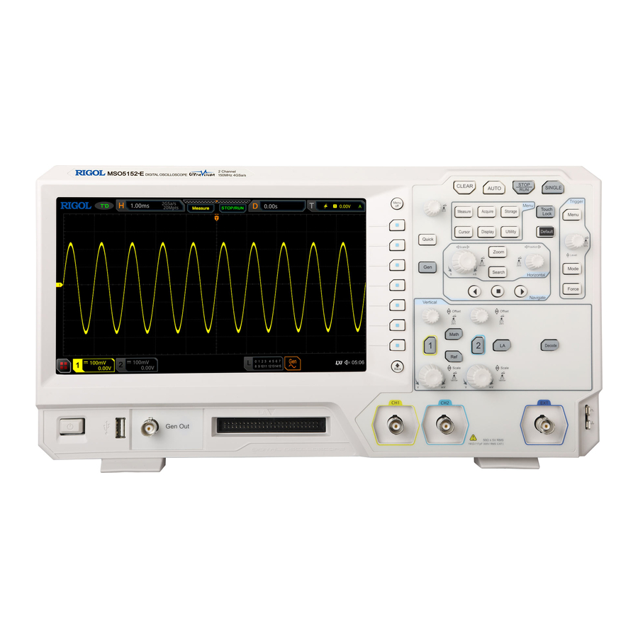
Chapter 1 Quick Start RIGOL Appearance and Dimensions Figure 1-1 Front View Unit: mm Figure 1-2 Vertical View Unit: mm MSO5000-E User Guide... -
Page 26: To Prepare For Use
Chapter 1 Quick Start RIGOL To Prepare for Use To Adjust the Supporting Legs You can unfold the supporting legs to use them as stands to tilt the instrument upwards for easier operation and observation, as shown in Figure 1-3. You can also fold the supporting legs for easier storage or shipment when the instrument is not in use. -
Page 27: Turn-On Checkout
After the self-test, the welcome screen is displayed. To Connect the Probe RIGOL provides the passive probe and the logic probe for MSO5000-E series. For MSO5000-E Series Datasheet specific probe models, please refer to . - Page 28 Chapter 1 Quick Start RIGOL Connect the logic probe: 1. Turn off the power supply of the device under test. 2. Connect the output terminal of the logic probe to the digital channel input terminal on the front panel of the oscilloscope in the correct direction, as shown in Figure 1-6.
- Page 29 Chapter 1 Quick Start RIGOL (b) Incorrect Connection of the Ground Lead Figure 1-7 Ground Lead Connection 5. Repeat the above steps to connect all digital signals. Note: The digital channel input terminal does not support hot plugging. Please do not ⚫...
-
Page 30: Function Inspection
Chapter 1 Quick Start RIGOL Function Inspection Press Default on the front panel, then a prompt message "Restore default settings?" is displayed. Press OK or tap OK to restore the instrument to its factory default settings. Connect the ground alligator clip of the probe to the "Ground Terminal" as shown in Figure 1-8 below. -
Page 31: Probe Compensation
Chapter 1 Quick Start RIGOL The probe compensation signal can only be used for probe compensation adjustment and cannot be used for calibration. Probe Compensation When the probes are used for the first time, you should compensate the probes to make them match the input channels of the oscilloscope. -
Page 32: Front Panel Overview
Chapter 1 Quick Start RIGOL Front Panel Overview 9 10 Figure 1-11 Front Panel Table 1-1 Front Panel Description Description Description Capacitive Touch Screen Trigger Control System Function Menu Operation Keys Horizontal Control System Function/Arbitrary Waveform Navigation Control key Generator Setting Key... -
Page 33: Rear Panel Overview
Chapter 1 Quick Start RIGOL Rear Panel Overview Figure 1-12 Rear Panel 1. Handle Rotate the handle upright to carry the instrument easily. Rotate it downward if you do not need to carry it. 2. HDMI Through this interface, you can connect the instrument to an external display equipped with the HDMI interface (e.g. - Page 34 Press Online upgrade or enable the touch screen to tap "Online upgrade", then a "System Update Information" window is displayed, requesting you whether to accept or cancel "RIGOL PRODUCT ONLINE UPGRADE SERVICE TERMS". Tap "Accept" to start online upgrade. Tap "Cancel"...
-
Page 35: Front Panel Function Overview
Decode: indicates the decode key. Press this key to open the decode setting ⚫ menu, and then you can set the decode options. MSO5000-E series supports the parallel decoding and many protocol decodings. (For details, refer to the descriptions in "Protocol Decoding"). -
Page 36: Horizontal
Chapter 1 Quick Start RIGOL would move up and down. Meanwhile, the offset information in the corresponding status label would change accordingly. Press down this knob to quickly reset the vertical offset to zero. Vertical SCALE: indicates the channel vertical scale knob. Modify the ⚫... -
Page 37: Trigger
Chapter 1 Quick Start RIGOL compressed form, and the timebase message (e.g. ) at the upper section of the screen would change accordingly. Press down this knob to quickly switch the horizontal timebase adjustment mode between "Coarse" and "Fine". Trigger Menu: Press this key to open the trigger operation ⚫... -
Page 38: Navigation Control Key
Chapter 1 Quick Start RIGOL Storage: Press this key to enter the file or waveform storage and load interface. The file types for storage include image, waveform, and setups. Besides, waveform load and setup load are supported. The disk management and file auto naming function are also supported in this menu. -
Page 39: Clear
Chapter 1 Quick Start RIGOL Clear Press this key to clear all the waveforms on the screen. If the oscilloscope is in the "RUN" state, new waveforms will continue being displayed. Auto Press this key to enable the waveform auto setting function. The... -
Page 40: Multifunction Knob
Chapter 1 Quick Start RIGOL Multifunction Knob Non-menu Operation: ⚫ In non-menu-operation mode, rotate this knob to adjust the brightness of waveform display. The settable screen brightness ranges from 1% to 100%. Turn it clockwise to increase the brightness, and turn it counterclockwise to decrease the brightness. -
Page 41: User Interface
Chapter 1 Quick Start RIGOL User Interface MSO5000-E series has a 9-inch WSVGA (1024× 600) LCD, with 256 level gray-scale display. The user interface displays the acquired waveforms, the setting information, and the measurement results. 5 6 7 10 11 12... - Page 42 Chapter 1 Quick Start RIGOL 3. Horizontal Timebase Represents the time length per grid in the horizontal axis of the screen. ⚫ Use Horizontal SCALE to modify this parameter. The adjustable range ⚫ of the horizontal timebase is different for different models.
- Page 43 Chapter 1 Quick Start RIGOL 12. Trigger LEVEL/Threshold Level When CH1, CH2, EXT, or EXT/5 is selected as the trigger source, you need ⚫ to set a proper trigger level. When D0-D15 is selected as the trigger source, you need to set a proper ⚫...
-
Page 44: Touch Screen Controls
Enable the touch screen and then tap this icon to enable the function navigation. Touch Screen Controls MSO5000-E series provides a 9-inch super large capacitive touch screen, which supports multi-touch and gesture operation. It has strong waveform display capability and excellent user experience. It features great convenience, high flexibility, and great sensitivity. -
Page 45: Tap
Chapter 1 Quick Start RIGOL Use one finger to touch the symbol or characters on the screen slightly, as shown in Figure 1-14. The functions of the tap action include: Tap the menu displayed on the screen to operate on the menu. -
Page 46: Rectangle Drawing
Chapter 1 Quick Start RIGOL keypad). Drag the marker to change the position of the marker. ⚫ Figure 1-16 Drag Gesture Rectangle Drawing Enable the function navigation, and then tap the "Draw rect" icon to switch to the rectangle drawing mode. Drag a finger from upper left to lower right across the screen to draw a rectangle on the screen, as shown in Figure 1-17 (a). - Page 47 Chapter 1 Quick Start RIGOL Select "Horizontal zoom in": expands the waveforms in the horizontal direction. ⚫ Select "Horizontal zoom out": compresses the waveforms in the horizontal direction. Select "Vertical zoom in": expands the waveforms in the vertical direction. Select ⚫...
-
Page 48: Parameter Setting Method
RIGOL Parameter Setting Method You can use the knob or enable the touch screen to set the parameters of MSO5000-E series. The common parameter setting methods are as follows: Method 1: For the parameters with the sign , rotate the multifunction knob on the front panel directly to select the parameter item or modify the parameter value. -
Page 49: To Use The Kensington Security Lock
Chapter 1 Quick Start RIGOL Method 4: For the parameters without the above signs, press the desired menu softkey to switch between the parameter items. This method is applicable to the parameters with only two available options. The above method is commonly used for the parameter settings of the oscilloscope. -
Page 50: To Use The Built-In Help System
Chapter 1 Quick Start RIGOL To Use the Built-in Help System The help system of this oscilloscope provides instructions for all the function keys on the front panel and their corresponding menu keys. The steps for opening the built-in help system are as follows: Press Utility →... -
Page 51: To View The Option Information And The Option Installation
To View the Option Information and the Option Installation MSO5000-E series oscilloscope provides multiple options to fulfill your measurement requirements. If you need any of these options, order them according to the Order No. available in "Appendix A: Accessories and Options", and then install the options according to this section. - Page 52 Then, you can install the option according to the following steps. 1) Obtain an option license (1) Log in to the RIGOL official website (www.rigol.com), click License Activation to enter the "Registered product license code" interface. (2) In the software license registration interface, input the correct key, serial number (press Utility →...
-
Page 53: Chapter 2 To Set The Vertical System
RIGOL Chapter 2 To Set the Vertical System MSO5000-E series provides two analog input channels (CH1 and CH2), and each channel is equipped with an independent vertical control system. The setting methods for the vertical systems of the two channels are the same. This chapter takes CH1 as an example to introduce the setting method for the vertical system. -
Page 54: To Enable Or Disable The Analog Channel
Chapter 2 To Set the Vertical System RIGOL To Enable or Disable the Analog Channel Enable the analog channel: Connect a signal to the channel connector of CH1, and then press 1 in the vertical control area (Vertical) on the front panel to enable CH1. Then, the backlight of the channel is illuminated. -
Page 55: To Adjust The Vertical Scale
Chapter 2 To Set the Vertical System RIGOL To Adjust the Vertical Scale Vertical scale indicates the voltage value per grid in the vertical axis of the screen. It is often expressed in V/div. While you adjust the vertical scale, the display amplitude of the waveform would enlarge or reduce. -
Page 56: Vertical Expansion
Chapter 2 To Set the Vertical System RIGOL Vertical Expansion When changing the vertical scale of the analog channel by rotating the Vertical SCALE knob, you can select to expand or compress the waveform around the "Center" or "GND" (Ground). By default, "GND" is selected under Expand. -
Page 57: Channel Coupling
CH1 setting menu to select the desired coupling mode. Bandwidth Limit MSO5000-E series supports the bandwidth limit function. Setting the bandwidth limit can reduce the noises in the displayed waveforms. For example, the signal under test is a pulse with high frequency oscillation. -
Page 58: Probe Ratio
Probe Ratio MSO5000-E series allows you to set the probe attenuation manually. To obtain the correct measurement results, you must set the probe ratio properly. By default, the probe ratio is 1X. -
Page 59: Input Impedance
Chapter 2 To Set the Vertical System RIGOL 10:1 20:1 50:1 100X 100:1 200X 200:1 500X 500:1 1000X 1000:1 2000X 2000:1 5000X 5000:1 10000X 10000:1 20000X 20000:1 50000X 50000:1 Input Impedance To reduce the circuit load between the oscilloscope and the circuit under test, this oscilloscope provides the default 1 MΩ... -
Page 60: Amplitude Unit
Chapter 2 To Set the Vertical System RIGOL (a) "Invert" Off (b) "Invert" On Figure 2-1 Waveform Invert Note: When the waveform invert is enabled, the trigger edge or the trigger polarity will change (e.g. Edge trigger, Pulse trigger, or Slope trigger). -
Page 61: Offset Cal
Chapter 2 To Set the Vertical System RIGOL Figure 2-2 Zero Offset Press 1 → More → Ch-Ch Skew, rotate the multifunction knob or use the numeric keypad to set the desired delay calibration time. The available range of the delay calibration time is from -100 ns to 100 ns. -
Page 62: Channel Label
Chapter 2 To Set the Vertical System RIGOL Channel Label The instrument uses the channel number to mark the corresponding channel by default. For ease of use, you can also set a label for each channel. For example, " ". - Page 63 Chapter 2 To Set the Vertical System RIGOL To delete or modify the input characters, rotate the multifunction knob or enable the touch screen to realize it. Rotate the multifunction knob : use the delete key to delete or modify the ⚫...
-
Page 65: Chapter 3 To Set The Horizontal System
Chapter 3 To Set the Horizontal System RIGOL Chapter 3 To Set the Horizontal System Contents in this chapter: To Adjust the Horizontal Timebase ◼ To Adjust the Horizontal Position ◼ Delayed Sweep ◼ MSO5000-E User Guide... -
Page 66: To Adjust The Horizontal Timebase
Chapter 3 To Set the Horizontal System RIGOL To Adjust the Horizontal Timebase Horizontal timebase, also called the horizontal scale, refers to the time of each grid in the horizontal direction of the screen. It is usually expressed in s/div. The adjustable range of the horizontal timebase is related to the model type. -
Page 67: To Adjust The Horizontal Position
Chapter 3 To Set the Horizontal System RIGOL timebase, and counterclockwise to increase the horizontal timebase. Note: When the delayed sweep is enabled, rotate the Horizontal SCALE knob to adjust the timebase for the delayed sweep. The delayed sweep timebase displayed in the center of the screen will be changed accordingly, as shown in the following figure. -
Page 68: Delayed Sweep
Chapter 3 To Set the Horizontal System RIGOL Note: When the delayed sweep is enabled, rotate the Horizontal POSITION knob to adjust the horizontal position of the delayed sweep (press down the knob to quickly reset it). The horizontal position of the delayed sweep at the upper-right corner of the screen changes accordingly. - Page 69 Chapter 3 To Set the Horizontal System RIGOL Waveform before enlargement: The waveform in the area that is not covered by subtransparent blue in the upper part of the screen is the waveform before enlargement. Its horizontal timebase (also called main timebase) is displayed at the upper-left corner of the screen. You can...
-
Page 71: Chapter 4 To Set The Sample System
Chapter 4 To Set the Sample System RIGOL Chapter 4 To Set the Sample System Contents in this chapter: Timebase Mode ◼ Acquisition Mode ◼ Sampling Mode ◼ Sample Rate ◼ LA Sample Rate ◼ Memory Depth ◼ LA Memory Depth ◼... -
Page 72: Timebase Mode
Chapter 4 To Set the Sample System RIGOL Timebase Mode MSO5000-E series supports three available timebase modes: YT mode, XY mode, and ROLL mode. By default, the timebase mode is YT. Press Acquire → Timebase Mode on the front panel, and then rotate the multifunction knob to select the desired timebase mode. - Page 73 Chapter 4 To Set the Sample System RIGOL According to sin=A/B or C/D, is the phase deviation angle between the two channels. The definitions of A, B, C, and D are shown in the above figure. The phase deviation angle is obtained, that is: =arcsin(A/B) or arcsin(C/D)
-
Page 74: Roll Mode
Chapter 4 To Set the Sample System RIGOL Note: In XY mode, CH1 and CH2 are forced to be enabled. The maximum sample rate ⚫ in XY mode is 2 GSa/s. Generally, a longer sample waveform can ensure better display effect of Lissajous figure. But due to the limitation of the memory depth, you have to reduce the waveform sample rate to acquire a longer waveform (refer to the introduction in "Memory Depth"). -
Page 75: Acquisition Mode
Chapter 4 To Set the Sample System RIGOL Acquisition Mode The acquisition mode is used to control how to generate waveform points from the sample points. MSO5000-E supports the following four acquisition modes: Normal, Average, Peak, and High Resolution. By default, the acquisition mode is Normal. -
Page 76: Peak
Chapter 4 To Set the Sample System RIGOL Figure 4-2 Waveforms before Averaging Figure 4-3 Waveforms after 128 Times of Averaging Peak In this mode, the oscilloscope acquires the maximum and minimum values of the signal within the sample interval to get the envelope of the signal or the narrow pulse that might be lost. -
Page 77: Sampling Mode
This oscilloscope only supports the real-time sampling mode. In this mode, the oscilloscope produce the waveform display from samples collected during one trigger event. The highest real-time sample rate on the analog channel of MSO5000-E series is 4 GSa/s. The current sample rate is displayed under CH SampleRate, and you can press More →... - Page 78 Chapter 4 To Set the Sample System RIGOL timebase or modify the memory depth. The impact of low sample rate on the waveform: 1. Waveform Distortion: when the sample rate is too low, some waveform details are lost, and the sample waveform displayed is rather different from the actual waveform of the signal.
-
Page 79: La Sample Rate
Chapter 4 To Set the Sample System RIGOL LA Sample Rate LA sampling is the process of sampling on the compared digital signals at a certain time interval. LA sample rate is the reciprocal of the time interval. For example, if the LA sample rate is 500 MSa/s, it indicates that the oscilloscope will make data acquisition on the digital signals at an interval of 2 ns. -
Page 80: La Memory Depth
Chapter 4 To Set the Sample System RIGOL ——indicates the sample rate. The unit is Sa/s. SRate ——indicates the horizontal timebase scale. The unit is s/div. TScale ——indicates the number of grids in the horizontal direction. The unit is div. -
Page 81: Horizontal Expansion
Chapter 4 To Set the Sample System RIGOL Horizontal Expansion Horizontal expansion indicates the reference position that the screen waveform is referenced to when it is horizontally expanded or compressed in adjusting the Horizontal SCALE knob. In YT mode, press Acquire → More → Expand and then rotate the multifunction knob to select the desired reference position. -
Page 83: Chapter 5 To Trigger The Oscilloscope
Chapter 5 To Trigger the Oscilloscope RIGOL Chapter 5 To Trigger the Oscilloscope As for trigger, you set certain trigger condition according to the requirement and when a waveform in the waveform stream meets this condition, the oscilloscope captures this waveform as well as the neighboring part, and displays them on the screen. -
Page 84: Trigger Source
Chapter 5 To Trigger the Oscilloscope RIGOL Trigger Source In the trigger control area (Trigger) on the front panel, press Menu → Source to select the desired source, or rotate the multi-function knob to select a desired source, then press down the knob to select it. You can also press Source continuously to select the trigger source or enable the touch screen to tap the desired trigger source and select it. -
Page 85: Trigger Level/Threshold Level
Chapter 5 To Trigger the Oscilloscope RIGOL Trigger LEVEL/Threshold Level The adjustment of the trigger level/threshold level is related to the type of the trigger source. When the trigger source is selected from CH1 and CH2, rotate the Trigger ⚫... -
Page 86: Trigger Mode
Chapter 5 To Trigger the Oscilloscope RIGOL Method 1: Enable the touch screen and drag the trigger level line to adjust the trigger level. For details about the operations, refer to descriptions in "Drag" section. Method 2: Enable the touch screen function, and tap the trigger setting label at the upper-right corner of the screen. -
Page 87: Trigger Coupling
Chapter 5 To Trigger the Oscilloscope RIGOL MSO5000-E provides three trigger modes: Auto, Normal, and Single. The default is Auto. In the trigger control area (Trigger) on the front panel, press Mode to quickly switch the current trigger mode. The trigger mode is displayed at the upper-right corner of the screen: A (Auto), N (Normal), and S (Single). -
Page 88: Trigger Holdoff
Chapter 5 To Trigger the Oscilloscope RIGOL Press Menu → Coupling in the trigger control area (Trigger) on the front panel. Then, rotate the multifunction knob to select the desired coupling mode (by default, it is DC). You can also press Coupling continuously to select it or enable the touch screen to select the desired coupling mode with touch gestures. -
Page 89: Noise Rejection
Chapter 5 To Trigger the Oscilloscope RIGOL Noise Rejection Noise rejection can reject the high frequency noise in the signal and reduce the possibility of miss-trigger of the oscilloscope. In the trigger control area (Trigger) on the front panel, press Menu to enter the trigger setting menu, then press Noise Reject continuously (for some triggers, Noise Reject is a sub menu under More, at this time, press Menu →... -
Page 90: Trigger Type
Chapter 5 To Trigger the Oscilloscope RIGOL Trigger Type MSO5000-E series oscilloscope provides the following trigger types. Edge Trigger ⚫ Pulse Trigger ⚫ Slope Trigger ⚫ Video Trigger ⚫ Pattern Trigger ⚫ Duration Trigger ⚫ Timeout Trigger ⚫ Window Trigger ⚫... -
Page 91: Edge Trigger
Chapter 5 To Trigger the Oscilloscope RIGOL Edge Trigger Triggers on the trigger level/threshold level of the specified edge of the input signal. Trigger Type: Press Menu → Type in the trigger control area (Trigger) on the front panel and rotate the multifunction knob to select "Edge", then press down the knob to... -
Page 92: Pulse Trigger
Chapter 5 To Trigger the Oscilloscope RIGOL Please refer to descriptions in "Trigger LEVEL/Threshold Level". The current trigger level/threshold level value is displayed at the upper-right corner of the screen. Pulse Trigger Triggers on the positive or negative pulse with a specified width. In this mode, the oscilloscope will trigger when the pulse width of the input signal satisfies the specified pulse width condition. - Page 93 Chapter 5 To Trigger the Oscilloscope RIGOL Polarity: Press Polarity continuously to select the desired polarity. The polarities available are positive polarity ( ) and negative polarity ( ). Trigger Condition: Press When, then rotate the multifunction knob to select the trigger condition, and then press down the knob to select the trigger condition.
-
Page 94: Slope Trigger
Chapter 5 To Trigger the Oscilloscope RIGOL Trigger Parameter Setting: Set the trigger parameters (trigger holdoff and noise rejection) under this trigger type. For details, refer to descriptions in "Trigger Holdoff" and "Noise Rejection". Trigger LEVEL/Threshold Level: Rotate the Trigger LEVEL knob to adjust the trigger level or threshold level. - Page 95 Chapter 5 To Trigger the Oscilloscope RIGOL Edge Type: Press Slope continuously to select the input signal edge on which the oscilloscope triggers. Rising: triggers on the rising edge of the input signal. ⚫ Falling: triggers on the falling edge of the input signal.
- Page 96 Chapter 5 To Trigger the Oscilloscope RIGOL to correctly trigger the signal and obtain a stable waveform. Press Level Select (when "<>" is selected as the trigger condition, Level Select is a sub-menu under More), then rotate the multifunction knob to select the desired level type for adjustment, and then press down the knob to select the type.
-
Page 97: Video Trigger
Video Trigger The video signal can include image information and timing information, which adopts different standards and formats. MSO5000-E series can trigger on the standard video signal field or line of NTSC (National Television Standards Committee), PAL (Phase Alternating Line), or SECAM (Sequential Couleur A Memoire). - Page 98 Chapter 5 To Trigger the Oscilloscope RIGOL 1080p/30Hz Progressive Scan 1125 1080p/25Hz Progressive Scan 1125 1080p/24Hz Progressive Scan 1125 1080i/60Hz Interlaced Scan 1125 1080i/50Hz Interlaced Scan 1125 Sync: Press Sync, then rotate the multifunction knob to select the sync type, and then press down the knob to select the type.
-
Page 99: Pattern Trigger
In the trigger debugging process of video signals, the frequency in different ⚫ part of the signal can be reflected by a different brightness, as RIGOL digital oscilloscope provides the intensity graded color display function. Experienced users can quickly judge the signal quality and discover abnormalities during the debugging process. - Page 100 Chapter 5 To Trigger the Oscilloscope RIGOL trigger source, can we obtain a stable trigger. Pattern Setting: Press Code, and rotate the multifunction knob to select the pattern of the currently selected channel. Press down the knob to select the pattern. You can also press Code continuously to select the pattern or enable the touch screen to select it.
-
Page 101: Duration Trigger
Chapter 5 To Trigger the Oscilloscope RIGOL Confirmation Key All Bits Move the cursor to the left Pattern Move the cursor to the right Figure 5-6 Virtual Keypad for Pattern Setting Note: Only one edge (rising or falling edge) can be specified in the pattern. If one edge item is currently defined and then another edge item is defined in another channel in the pattern, then a prompt message "Invalid input"... - Page 102 Chapter 5 To Trigger the Oscilloscope RIGOL Figure 5-7 Duration Trigger Trigger Type: Press Type, and then rotate the multifunction knob to select "Duration". Press down the knob to select the trigger type. Then, the current trigger setting information is displayed at the upper-right corner of the screen, as shown in the figure below.
- Page 103 Chapter 5 To Trigger the Oscilloscope RIGOL Trigger Condition: Press When, then rotate the multifunction knob to select the trigger condition, and then press down the knob to select the trigger condition. You can also press When continuously to select the trigger condition or enable the touch screen to tap the desired trigger condition and select it.
-
Page 104: Timeout Trigger
Chapter 5 To Trigger the Oscilloscope RIGOL Timeout Trigger In Timeout trigger, the oscilloscope triggers when the time interval (△T) (the time from when the rising edge (or falling edge) of the input signal passes through the trigger level to the time from when the neighboring falling edge (or rising edge) passes through the trigger level) is greater than the preset timeout value, as shown in the figure below. -
Page 105: Runt Trigger
Chapter 5 To Trigger the Oscilloscope RIGOL Timeout Value: Timeout value represents the maximum time that the signal remains idle before the signal passes through the trigger level. Press Timeout, and then rotate the multifunction knob or use the pop-up numeric keypad to set the timeout value of Timeout trigger. - Page 106 Chapter 5 To Trigger the Oscilloscope RIGOL descriptions in "Trigger Source". The current trigger source is displayed at the upper-right corner of the screen. Note: Only when we select the channel (that has been input with signals) as the trigger source, can we obtain a stable trigger.
-
Page 107: Window Trigger
Chapter 5 To Trigger the Oscilloscope RIGOL and they move up and down with the change of the trigger level. At the same time, the real-time trigger level information is displayed at the lower-left corner of the screen (as shown in the figure below, H indicates the upper limit of the trigger level, L indicates the lower limit of the trigger level, and △... - Page 108 Chapter 5 To Trigger the Oscilloscope RIGOL Edge Type: Press Slope, and then rotate the multifunction knob to select the input signal the edge on which the oscilloscope triggers. You can also press the Slope key continuously or enable the touch screen to select the desired edge type.
-
Page 109: Delay Trigger
Chapter 5 To Trigger the Oscilloscope RIGOL of the screen (as shown in the figure below, H indicates the upper limit of the trigger level, L indicates the lower limit of the trigger level, and △ indicates the trigger level deviation). - Page 110 Chapter 5 To Trigger the Oscilloscope RIGOL can also press Type continuously to select the trigger type or enable the touch screen to tap the desired trigger type and select it. Source A: Press SourceA to select CH1-CH2 or D0-D15 as the trigger source of Source A. For details, please refer to descriptions in "Trigger Source".
-
Page 111: Setup/Hold Trigger
Chapter 5 To Trigger the Oscilloscope RIGOL Delay trigger. Note: The lower time limit must be smaller than the upper time limit. Trigger Mode: In the trigger control area (Trigger) on the front panel, press Mode to quickly switch the current trigger mode. For details, refer to descriptions in "Trigger Mode". - Page 112 Chapter 5 To Trigger the Oscilloscope RIGOL figure below. You can also press Type continuously to select the trigger type or enable the touch screen to tap the desired trigger type and select it. Clock Source: Press SCL to set the signal source of the clock line. It can be set to CH1-CH2 or D0-D15.
-
Page 113: Nth Edge Trigger
Chapter 5 To Trigger the Oscilloscope RIGOL the current trigger mode. For details, refer to descriptions in "Trigger Mode". Trigger Parameter Setting: Set the trigger parameter (noise rejection) under this trigger type. For details, refer to descriptions in "Noise Rejection". -
Page 114: Rs232 Trigger (Option)
The frame consists of 1 start bit, 5-8 data bits, 1 check bit, and 1-2 stop bits. Its format is as shown in the figure below. MSO5000-E series oscilloscope triggers when the start frame, error frame, check error, or the specified data of the RS232 signal is detected. - Page 115 Chapter 5 To Trigger the Oscilloscope RIGOL Start Bit Stop Bit Data Bits Check Bit Figure 5-13 Schematic Diagram of RS232 Protocol Trigger Type: Press Type, and then rotate the multifunction knob to select "RS232". Press down the knob to select the trigger type. Then, the current trigger setting information is displayed at the upper-right corner of the screen, as shown in the figure below.
- Page 116 Chapter 5 To Trigger the Oscilloscope RIGOL Parity: Used to verify whether data are properly transmitted. Press More → Parity, then rotate the multifunction knob to select the desired parity. Then press down the knob to select it. You can also press Parity continuously or enable the touch screen to select the parity.
-
Page 117: I2C Trigger (Option)
Chapter 5 To Trigger the Oscilloscope RIGOL I2C Trigger (Option) I2C is a 2-wire serial bus used to connect the microcontroller and its peripheral device. It is a bus standard widely used in the microelectronic communication control field. The I2C serial bus consists of SCL and SDA. Its transmission rate is determined by SCL, and its transmission data is determined by SDA, as shown in the figure below. - Page 118 Chapter 5 To Trigger the Oscilloscope RIGOL high level. Stop: triggers when SDA data transitions from low level to high level while SCL is ⚫ high level. Restart: triggers when another start condition occurs before a stop condition. ⚫ MissedAck: triggers when the SDA data is high level during any acknowledgment ⚫...
-
Page 119: Spi Trigger (Option)
Chapter 5 To Trigger the Oscilloscope RIGOL Press Bytes, then rotate the multifunction knob or use the pop-up ➢ numeric keypad to set the length of the data. Its range is from 1 to 5. Press More → Addr Bits, and rotate the multifunction knob to select ➢... - Page 120 Chapter 5 To Trigger the Oscilloscope RIGOL Trigger Type: Press Type, and then rotate the multifunction knob to select "SPI". Press down the knob to select the trigger type. Then, the current trigger setting information is displayed at the upper-right corner of the screen, as shown in the figure below. You can also press Type continuously to select the trigger type or enable the touch screen to tap the desired trigger type and select it.
-
Page 121: Can Trigger (Option)
Chapter 5 To Trigger the Oscilloscope RIGOL Trigger Mode: In the trigger control area (Trigger) on the front panel, press Mode to quickly switch the current trigger mode. For details, refer to descriptions in "Trigger Mode". Trigger Parameter Setting: Set the trigger parameter (noise rejection) under this trigger type. For details, refer to descriptions in "Noise Rejection". - Page 122 Chapter 5 To Trigger the Oscilloscope RIGOL Trigger Condition: Press When to select the desired trigger condition. SOF: triggers at the start of a frame. ⚫ EOF: triggers at the end of a frame. ⚫ Remote ID: triggers on the remote frame with the specified ID. Set the following ⚫...
- Page 123 Chapter 5 To Trigger the Oscilloscope RIGOL Baud Rate: Press More → Baud to set the baud rate. Three setting methods are available for baud rate: Press Baud, then set the user-defined baud rate with the displayed numeric ⚫ keypad.
-
Page 124: Flexray Trigger (Option)
Chapter 5 To Trigger the Oscilloscope RIGOL FlexRay Trigger (Option) MSO5000-E can trigger on the specified frame, symbol, error, or position of the FlexRay bus. FlexRay is a type of differential serial bus configured with three consecutive segments (i.g. header, payload, and trailer). Its data transmission rate is up to 10 Mb/s. - Page 125 Chapter 5 To Trigger the Oscilloscope RIGOL matches the FlexRay bus signal. Then press down the knob to select the baud rate. You can also press Baud continuously or enable the touch screen to select it. The available baud rates are 2.5 Mbps, 5 Mbps, and 10 Mbps.
-
Page 126: Lin Trigger (Option)
Chapter 5 To Trigger the Oscilloscope RIGOL Trigger Mode: In the trigger control area (Trigger) on the front panel, press Mode to quickly switch the current trigger mode. For details, refer to descriptions in "Trigger Mode". Trigger Parameter Setting: Set the trigger parameter (noise rejection) under this trigger type. For details, refer to descriptions in "Noise Rejection". - Page 127 Chapter 5 To Trigger the Oscilloscope RIGOL Sync: triggers on the last bit of the sync field. ⚫ ID: triggers when the frame with an ID equal to the selected value is detected. ⚫ Press ID, then rotate the multifunction knob or use the pop-up numeric keypad to set ID.
-
Page 128: I2S Trigger (Option)
Chapter 5 To Trigger the Oscilloscope RIGOL One Bit Figure 5-21 Sample Position Press More → Sample Position, then rotate the multifunction knob or use the pop-up numeric keypad to set the sample position. The settable range is from 10% to 90%. - Page 129 Chapter 5 To Trigger the Oscilloscope RIGOL Figure 5-22 Sequential Chart of I2S Bus Trigger Type: Press Type, and then rotate the multifunction knob to select "I2S". Press down the knob to select the trigger type. Then, the current trigger setting information is displayed at the upper-right corner of the screen, as shown in the figure below.
- Page 130 Chapter 5 To Trigger the Oscilloscope RIGOL ≠: triggers when the channel's data do not equal the set data value. Press Data ⚫ to set the data bit. For setting methods, refer to descriptions in "I2C Trigger (Option)". >: triggers when the channel's data are greater than the set data value. Press ⚫...
-
Page 131: Mil-Std-1553 Trigger (Option)
Chapter 5 To Trigger the Oscilloscope RIGOL Trigger Parameter Setting: Set the trigger parameter (noise rejection) under this trigger type. For details, refer to descriptions in "Noise Rejection". Trigger LEVEL/Threshold Level: Rotate the Trigger LEVEL knob to adjust the trigger level/threshold level. Refer to "Trigger LEVEL/Threshold Level". - Page 132 Chapter 5 To Trigger the Oscilloscope RIGOL Trigger Type: Press Type, and then rotate the multifunction knob to select "MIL-STD-1553". Press down the knob to select the trigger type. Then, the current trigger setting information is displayed at the upper-right corner of the screen, as shown in the figure below.
- Page 133 Chapter 5 To Trigger the Oscilloscope RIGOL RTA: triggers on the specified remote terminal address. After this trigger ⚫ condition is selected, press RTA to set the remote terminal address. For setting methods, refer to descriptions in "I2C Trigger (Option)".
-
Page 134: Zone Trigger
"Noise Rejection". Zone Trigger MSO5000-E series oscilloscope supports the zone trigger and provides two rectangle areas: Trigger zone A and Trigger zone B. You can set the trigger conditions to "Intersect" or "Not intersect". Refer to "Rectangle Drawing" to select "Trigger zone A"... -
Page 135: Trigger Output Connector
If you enable both Trigger zone A and Trigger zone B, then perform the "A&&B" operation, and it will become the final trigger condition. Trigger Output Connector The trigger output connector ([TRIG OUT]) on the rear panel of MSO5000-E series can output trigger signals (hardware trigger) determined by the current setting. MSO5000-E User Guide... - Page 136 Chapter 5 To Trigger the Oscilloscope RIGOL Trigger Output Connector Figure 5-24 Trigger Output Connector Press Utility → System → AUX Out to select "TrigOut”. A signal which reflects the current capture rate of the oscilloscope can be output from the [TRIG OUT] connector each time a trigger is generated by the oscilloscope.
-
Page 137: Chapter 6 Operations And Measurements
Chapter 6 Operations and Measurements RIGOL Chapter 6 Operations and Measurements MSO5000-E can perform math operations, auto measurements, and cursor measurements on sampled and displayed data. Contents in this chapter: Math Operation ◼ Auto Measurement ◼ Cursor Measurement ◼ MSO5000-E User Guide... -
Page 138: Math Operation
The results of the math operation can be further measured. This oscilloscope supports enabling the four math operations at the same time, as shown in the figure below. MSO5000-E series can realize multiple math operations between waveforms of different channels, including arithmetic operations (A+B, A-B, A× B, and A/B) ⚫... -
Page 139: Subtraction
Chapter 6 Operations and Measurements RIGOL to select the channel. You can also press SourceA and SourceB continuously or enable the touch screen to select the channel. The available channels for Source A and Source B are CH1-CH2 and Ref1-Ref10. -
Page 140: Multiplication
Chapter 6 Operations and Measurements RIGOL Source A and Source B are CH1-CH2 and Ref1-Ref10. Note: The available channels for Math2 are CH1-CH2, Ref1-Ref10 or Math1. The available channels for Math3 are CH1-CH2, Ref1-Ref10, Math1 or Math2. The available channels for Math4 are CH1-CH2, Ref1-Ref10, Math1, Math2 or Math3. -
Page 141: Division
Chapter 6 Operations and Measurements RIGOL The available channels for Math3 are CH1-CH2, Ref1-Ref10, Math1 or Math2. The available channels for Math4 are CH1-CH2, Ref1-Ref10, Math1, Math2 or Math3. Only the channels that have been enabled currently can be selected. -
Page 142: Fft
FFT (Fast Fourier Transform) is used to transform time-domain signals to frequency-domain components (frequency spectrum). MSO5000-E series oscilloscope provides FFT operation function which enables you to observe the time-domain waveform and spectrum of the signal at the same time. FFT operation can facilitate the following works: Measure harmonic components and distortion in the system;... - Page 143 Chapter 6 Operations and Measurements RIGOL frequency, and resolution are displayed at the bottom of the screen, as shown in the following figure. Of which, FFT resolution is the quotient of the sample rate and the number of FFT points. If the number of FFT points is a fixed value (65535 at most), then the lower the sample rate, the higher the resolution.
- Page 144 ⚫ Spectral leakage can be considerably decreased when a window function is used. MSO5000-E series provides 6 FFT window functions (as shown in Table 6-1) which have different characteristics and are applicable to measuring different waveforms. You need to select the window function according to the characteristics of the waveform to be measured.
- Page 145 Chapter 6 Operations and Measurements RIGOL Table 6-1 Window Function Window Waveforms Applicable to the Characteristics Function Window Function Rectangular Best frequency Transient or short pulse, the signal resolution levels before and after the Poorest multiplication are basically the same.
-
Page 146: And" Operation
Chapter 6 Operations and Measurements RIGOL FFT shortcut operation: Enable the touch screen, and then tap the function navigation icon at the lower-left corner of the screen to open the function navigation. Then, tap the "FFT" icon to open the FFT menu. This oscilloscope supports 4 FFTs: FFT1, FFT2, FFT3, and FFT4. -
Page 147: Or" Operation
Chapter 6 Operations and Measurements RIGOL Press Offset, and then rotate the multifunction knob to adjust the vertical ⚫ offset of the operation results. You can also enable the touch screen and use the "Drag" gesture to adjust the vertical offset. -
Page 148: Xor" Operation
Chapter 6 Operations and Measurements RIGOL refer to descriptions in "Parameter Setting Method". If Source A (or Source B) selects CH2, press More → Thre.CH2 to set the ➢ threshold of Source A (or Source B) in logic operation. For setting methods, refer to descriptions in "Parameter Setting Method". -
Page 149: Not" Operation
Chapter 6 Operations and Measurements RIGOL or enable the touch screen to select the channel. The available channels for Source A and Source B are CH1-CH2 and D0-D15. Note: Only the channels that have been enabled currently can be selected. -
Page 150: Intg
Chapter 6 Operations and Measurements RIGOL function. Press SourceA, and rotate the multifunction knob to select the channel for ⚫ Source A. Then press down the knob to select the channel. You can also press SourceA continuously or enable the touch screen to select the channel. The available channels for Source A and Source B are CH1-CH2 and D0-D15. -
Page 151: Diff
Chapter 6 Operations and Measurements RIGOL Note: The available channels for Math2 are CH1-CH2, Ref1-Ref10 or Math1. The available channels for Math3 are CH1-CH2, Ref1-Ref10, Math1 or Math2. The available channels for Math4 are CH1-CH2, Ref1-Ref10, Math1, Math2 or Math3. Only the channels that have been enabled currently can be selected. -
Page 152: Sqrt
Chapter 6 Operations and Measurements RIGOL Press Offset to set the vertical offset of the operation results. For setting ⚫ methods, refer to the descriptions in "Parameter Setting Method". You can also enable the touch screen and use the "Drag" gesture to adjust the vertical offset. -
Page 153: Lg (Base 10 Exponential)
Chapter 6 Operations and Measurements RIGOL available channels for Source A are CH1-CH2 and Ref1-Ref10. Note: The available channels for Math2 are CH1-CH2, Ref1-Ref10 or Math1. The available channels for Math3 are CH1-CH2, Ref1-Ref10, Math1 or Math2. The available channels for Math4 are CH1-CH2, Ref1-Ref10, Math1, Math2 or Math3. - Page 154 Chapter 6 Operations and Measurements RIGOL methods, refer to the descriptions in "Parameter Setting Method". You can also enable the touch screen and use the "Drag" gesture to adjust the vertical offset. Press Scale to set the vertical scale of the operation results. For setting methods, ⚫...
-
Page 155: Exp
Chapter 6 Operations and Measurements RIGOL scale. Press AutoSetting to adjust the vertical scale and offset of the operation ⚫ results to an optimal value based on the current configuration, so as to better observe. Press More → Invert to enable or disable the inverted display function of the ⚫... -
Page 156: Abs
Chapter 6 Operations and Measurements RIGOL Press More → Label to set the label for math operation results. For details, ⚫ refer to descriptions in "Math Operation Label". Press More → Color Grade to enable or disable the color grade display of the ⚫... -
Page 157: Low Pass
Chapter 6 Operations and Measurements RIGOL Low Pass Only allows the signals whose frequencies are lower than the current upper limit frequency to pass. Press Math → Math1 → Operator to select "LowPass": Press Operation continuously to enable or disable the "LowPass" operation ⚫... -
Page 158: High Pass
Chapter 6 Operations and Measurements RIGOL High Pass Only allows the signals whose frequencies are higher than the current lower limit frequency to pass. Press Math → Math1 → Operator to select "HighPass": Press Operation continuously to enable or disable the "HighPass" operation ⚫... -
Page 159: Band Pass
Chapter 6 Operations and Measurements RIGOL Band Pass Only allows the signals whose frequencies are higher than the current lower limit frequency and lower than the current upper limit frequency to pass. Press Math → Math1 → Operator to select "BandPass": Press Operation continuously to enable or disable the "BandPass"... -
Page 160: Band Stop
Chapter 6 Operations and Measurements RIGOL Band Stop Only allows the signals whose frequencies are lower than the current lower limit frequency and higher than the current upper limit frequency to pass. Press Math → Math1 → Operator to select "BandStop": Press Operation continuously to enable or disable the "BandStop"... -
Page 161: Ax+B
Chapter 6 Operations and Measurements RIGOL AX+B Applies a linear function to the selected source, and displays the results. Press Math → Math1 → Operator to select "AX+B": Press Operation continuously to enable or disable the "AX+B" operation ⚫ function. -
Page 162: Math Operation Label
Chapter 6 Operations and Measurements RIGOL Math Operation Label Press Label to enter the label setting menu. Press Display Label continuously to enable or disable the label display of the ⚫ waveform. If it is enabled, the label will be displayed at the left side of the waveform. -
Page 163: Auto Measurement
Chapter 6 Operations and Measurements RIGOL Auto Measurement MSO5000-E series provides auto measurements for 41 waveform parameters, as well as the statistics and analysis of the measurement results. Quick Measurement after AUTO When the oscilloscope is correctly connected and has detected a valid input signal, press AUTO to enable the waveform auto setting function and open the auto setting function menu. - Page 164 Chapter 6 Operations and Measurements RIGOL If you lock the Auto function and then exit the auto setting function menu, you can press Utility → More → Auto Config to enter the auto setting function menu again to unlock the Auto function.
- Page 165 Chapter 6 Operations and Measurements RIGOL should be greater than or equal to 35 Hz, the amplitude greater than or equal to 5 mV. If not meeting the conditions, the waveform auto setting function may be invalid. MSO5000-E User Guide...
-
Page 166: Measurement Parameter
Chapter 6 Operations and Measurements RIGOL Measurement Parameter Press Measure on the front panel to enter the measurement setting menu. You can set the measurement source, enable or disable the all measurement function, the statistical analysis function, and etc. You can also quickly make measurements for 41 waveform parameters. - Page 167 Chapter 6 Operations and Measurements RIGOL 6. -Width: indicates the time between the threshold middle value of a falling edge to the threshold middle value of the next rising edge. 7. +Duty: indicates the ratio of the positive pulse width to the period.
- Page 168 Chapter 6 Operations and Measurements RIGOL Rising Edge Count = n Threshold Upper Limit Threshold Lower Limit 4. Falling Edge Count: The number of falling edges that fall from above the threshold upper limit to below the threshold lower limit.
- Page 169 Chapter 6 Operations and Measurements RIGOL 3. Delay A →B : indicates the time difference between the threshold middle values of the rising edge of Source A and the falling edge of Source B. Negative delay indicates that the rising edge of Source A occurred after the falling edge of Source B.
- Page 170 Chapter 6 Operations and Measurements RIGOL Note: Source A and Source B can be any channel among CH1-CH2, Math1-Math4, or ⚫ D0-D15. You can press Measure → Add to enter the sub-menu to set the parameters. The default threshold middle value is 50%. You can press Measure → Setting ⚫...
- Page 171 Chapter 6 Operations and Measurements RIGOL gating area. The formula is shown as follows: ∑ Average Wherein, is the measurement result of the i th point, and n is the number of points being measured. 11. VRMS: indicates the root mean square value on the whole waveform or in the gating area.
-
Page 172: Measurement Settings
Chapter 6 Operations and Measurements RIGOL reference is negative. The area measured is the algebraic sum of the whole period area. Measurement Settings 1. Measurement Category Press Measure → Add → Category to select "Horizontal", "Vertical", or "Other". Meanwhile, the specific measurement parameters are displayed on the screen, as shown in the figure below. - Page 173 Chapter 6 Operations and Measurements RIGOL parameters. When you rotate the multifunction knob to switch from the ⚫ measurement parameter area to the measurement category area, you need to press down the knob to select the desired measurement category. In the measurement category area, rotate the multifunction knob ⚫...
- Page 174 Chapter 6 Operations and Measurements RIGOL Note: When the memory depth is less than or equal to 1K points or the "High Res" mode is opened, the "Precision" measurement mode will make measurements according to the methods of "Normal" measurement mode.
-
Page 175: Remove The Measurement Result
Chapter 6 Operations and Measurements RIGOL Modifying the threshold will affect the measurement results of ⚫ the time, delay and phase parameters. If you select "Manual" under Amp Method, the measurement ⚫ results of other parameters may be affected. "Histogram" and "Max-Min" are the internal measurement ⚫... -
Page 176: All Measurement
Chapter 6 Operations and Measurements RIGOL Press Measure → Statistic to enter the sub-menu of "Statistic". Press Statistic to enable or disable the statistical function. ⚫ Press Reset Stat. to clear the history statistics data and makes statistics again. ⚫... - Page 177 Chapter 6 Operations and Measurements RIGOL X Cursor (Cursor A) X Cursor (Cursor B) Y Cursor (Cursor A) Y Cursor (Cursor B) X Cursor ⚫ X cursor is a vertical solid/dotted line that is used to make horizontal adjustments. It can be used to measure time (s), frequency (Hz), phase (°), and ratio (%).
-
Page 178: Manual Mode
Chapter 6 Operations and Measurements RIGOL Note: When the Timebase Mode is set to "XY", the XY cursor measurement mode is valid. Manual Mode In this mode, you can adjust the cursor manually to measure the value of the waveforms of the specified source at the current cursor. The measurement results are displayed at the upper-left corner of the screen. - Page 179 Chapter 6 Operations and Measurements RIGOL source channels are None, CH1-CH2, LA, and Math1-Math4. Note: Only channels currently enabled can be selected. ⚫ When "LA" is selected under Source, Select is grayed out and disabled. By ⚫ default, "X" is selected under Select.
- Page 180 Chapter 6 Operations and Measurements RIGOL 5. Set the Horizontal/Vertical Measurement Unit When "X" is selected under Select, you can set the horizontal measurement ⚫ unit. When the source can be Math1-Math4, this menu is grayed out and disabled. Press More → Hori. Unit, and rotate the multifunction knob to select the horizontal measurement unit.
- Page 181 Chapter 6 Operations and Measurements RIGOL The available units include "Source" and "Percent(%)". Source: measures the amplitude at Y Cursor (taking the channel ➢ ground point as the reference). The measurement results include AY, BY, and △Y (its unit is consistent with that of the current source).
-
Page 182: Track Mode
Chapter 6 Operations and Measurements RIGOL Track Mode In this mode, you can adjust the two pairs of cursors (Cursor A and Cursor B) to measure the X and Y values on two different sources respectively. The points being measured on Cursor A and Cursor B are marked by respectively. - Page 183 Chapter 6 Operations and Measurements RIGOL 2. Select the Track Axis Press Track to select "X" or "Y" as the current track axis. The default is "X". X: tracks X Cursor and measures the value at X Cursor. ⚫ Y: tracks Y Cursor and measures the time of the first point at the left side of ⚫...
-
Page 184: Xy Mode
Chapter 6 Operations and Measurements RIGOL Track Measurement (before Horizontal Expansion): Track Measurement (after Horizontal Expansion): XY Mode XY mode is only available when the horizontal timebase mode is "XY" (refer to "Timebase Mode"). In this mode, two pairs of cursors will appear. You can adjust the cursor positions to measure the X and Y values at the crossing points of the two pairs of cursors. - Page 185 Chapter 6 Operations and Measurements RIGOL BX: indicates the X value at Cursor B. ⚫ BY: indicates the Y value at Cursor B. ⚫ △X: indicates the horizontal spacing between Cursor A and Cursor B. ⚫ △Y: indicates the vertical spacing between Cursor A and Cursor B.
-
Page 186: Measure Mode
Chapter 6 Operations and Measurements RIGOL Phase deviation between two signals Frequency ratio between two signals Figure 6-4 Lissajous Schematic Diagram Measure Mode Press Mode to select "Measure". In this mode, the cursor position for measurement is displayed. Press Indicator continuously to enable or disable the indicator. If it is enabled, one or multiple cursors are displayed on the screen. -
Page 187: Chapter 7 Digital Voltmeter (Dvm) And Frequency Counter
RIGOL Chapter 7 Digital Voltmeter (DVM) and Frequency Counter MSO5000-E series oscilloscope provides a built-in digital voltmeter (DVM) and frequency counter, which enable you to perform an accurate measurement, improving user experience in counter and frequency measurement. Contents in this chapter: Digital Voltmeter (DVM) ◼... -
Page 188: Digital Voltmeter (Dvm)
Chapter 7 Digital Voltmeter (DVM) and Frequency Counter RIGOL Digital Voltmeter (DVM) The built-in DVM of this oscilloscope provides 3-digit voltage measurements on any analog channel. DVM measurements are asynchronous from the oscilloscope’s acquisition system and are always acquiring. Press Measure → Analyze → DVM to open the DVM setting menu, or enable the... -
Page 189: To Select Measurement Mode
Chapter 7 Digital Voltmeter (DVM) and Frequency Counter RIGOL Note: Even if the analog channel (CH1 or CH2) is not enabled, you can still perform the DVM measurement. To Select Measurement Mode Press Mode in the "DVM" setting menu, then rotate the multifunction knob select the desired mode, and then press down the knob to select the mode. -
Page 190: Frequency Counter
Chapter 7 Digital Voltmeter (DVM) and Frequency Counter RIGOL Frequency Counter The frequency counter analysis function provides frequency, period, or edge event counter measurements on any analog channel. Press Measure → Analyze → Counter to open the frequency counter setting menu, or enable the touch screen and then tap the function navigation icon the lower-left corner of the screen to open the function navigation. -
Page 191: To Set Resolution
Chapter 7 Digital Voltmeter (DVM) and Frequency Counter RIGOL select the desired measurement item, and then press down the knob to select the item. You can also press Measure continuously or enable the touch screen to tap the desired measurement item and select it. -
Page 193: Chapter 8 Power Analysis (Option)
RIGOL Chapter 8 Power Analysis (Option) MSO5000-E series oscilloscope provides an optional power analysis function, which can help you easily analyze the efficiency and reliability of the switch-mode power supplies. With the power analysis function, you can analyze the power quality and output ripple noise of the input power. -
Page 194: Power Quality
Chapter 8 Power Analysis (Option) RIGOL Power Quality By analyzing the power quality, you can test the quality of AC input lines. The specific measurement parameters for power quality analysis include V_RMS, I_RMS, real power, apparent power, reactive power, power factor, reference frequency, phase angle, impedance, voltage crest factor, and current crest factor. - Page 195 Chapter 8 Power Analysis (Option) RIGOL numeric keypad to set the middle value. The middle value is limited by the settings of the upper limit and lower limit. Press Lower, then rotate the multifunction knob or use the pop-up ➢...
-
Page 196: Ripple
Chapter 8 Power Analysis (Option) RIGOL Figure 8-1 Connection Diagram of Power Quality Analysis Ripple Power ripple is an important parameter for evaluating DC power supply, which indicates the ripple quantity of the output DC voltage. The ripple analysis can measure the current value, average value, minimum value, maximum value, standard deviation, and count value of the ripples on the power output terminal. - Page 197 Chapter 8 Power Analysis (Option) RIGOL the figure below. You can also enable the touch screen to tap the icon at the right-upper corner of the statistical results window to close it. View the Connection Diagram ⚫ Press Tips, and then the connection diagram of the ripple analysis is displayed on the screen.
-
Page 199: Chapter 9 Histogram Analysis
Chapter 9 Histogram Analysis RIGOL Chapter 9 Histogram Analysis MSO5000-E series oscilloscope supports the standard histogram analysis function, enabling you to judge the trend of waveforms, and quickly locate the potential problems of the signal. Contents in this chapter: To Enable or Disable the Histogram Function ◼... -
Page 200: To Enable Or Disable The Histogram Function
RIGOL To Enable or Disable the Histogram Function The histogram analysis function supported by the MSO5000-E series is available to provide a statistical view of waveforms or measurement results. It can be classified into horizontal histogram, vertical histogram, and measurement histogram. With the... -
Page 201: To Select The Histogram Source
Chapter 9 Histogram Analysis RIGOL To Select the Histogram Source If "Horizontal" or "Vertical" is selected under Type, you need to set the source (CH1-CH2). Press Source, then rotate the multifunction knob to select the desired source, and then press down the knob to select the source. You can also press Source continuously or enable the touch screen to select it. -
Page 202: To Reset
Chapter 9 Histogram Analysis RIGOL Sum: indicates the sum of all bins (buckets) in the histogram. ⚫ Peaks: indicates the maximum number of hits in any single bin. ⚫ Max: indicates the maximum value within the histogram range. ⚫ Min: indicates the minimum value within the histogram range. -
Page 203: Chapter 10 Digital Channel
RIGOL Chapter 10 Digital Channel MSO5000-E series oscilloscope has a standard configuration of the logic analyzer (LA) function, and it has 16 digital channels. The default channel label is D15-D0. The oscilloscope compares the voltages acquired in each sample with the preset logic threshold. -
Page 204: To Select The Digital Channel
Chapter 10 Digital Channel RIGOL To Select the Digital Channel Press LA on the front panel to enter the LA setting menu. Press Select to open the channel menu, and rotate the multifunction knob to select the channel. You can also press Select continuously or enable the touch screen to select it. -
Page 205: To Set The Threshold And Calibrate Probe
Chapter 10 Digital Channel RIGOL Enable/disable a single digital channel ⚫ Press Dx On/Off to open the channel selection list. Rotate the multifunction knob to select a channel, and then press down the knob to enable or disable it. You can also press Dx On/Off continuously to switch to select any channel, and press down the multifunction knob to enable or disable the channel. -
Page 206: Auto Arrangement Setting
Chapter 10 Digital Channel RIGOL at the right side of the threshold field, and then the threshold selection list is displayed. Tap to select the preset threshold. Or tap the threshold input field and input the value with the pop-up numeric keypad. -
Page 207: Group Setting
Chapter 10 Digital Channel RIGOL Enable or disable the label display ⚫ Press Display continuously to enable or disable the display of the channel label. If it is enabled, the label will be displayed at the left side of the waveform. -
Page 208: Waveform Color Of The Digital Channel
Chapter 10 Digital Channel RIGOL knob to ungroup the channels. Note: You can only ungroup the digital channels. ⚫ If no group is set, the Ungroup menu and the Group On/Off menu are ⚫ grayed out and disabled. Waveform Color of the Digital Channel When the digital channel is enabled, its corresponding waveforms and label are displayed on the screen. -
Page 209: Chapter 11 Protocol Decoding
Protocol decoding is the basis of protocol analysis. Only protocol analyses with correct protocol decoding are acceptable, and only correct protocol decoding can identify more error information. MSO5000-E series provides four bus decoding modules (Decode 1, Decode 2, Decode 3, and Decode 4) to make common... -
Page 210: Parallel Decoding
Chapter 11 Protocol Decoding RIGOL Parallel Decoding Parallel bus consists of clock line and data line. As shown in the figure below, CLK is the clock line, whereas Bit0 and Bit1 are the 0 bit and 1st bit on the data line respectively. - Page 211 Chapter 11 Protocol Decoding RIGOL Falling : samples the channel data on the falling edge of the clock. Both : samples the channel data on both the rising edge and the falling edge of the clock. Set the threshold ⚫...
- Page 212 Chapter 11 Protocol Decoding RIGOL automatically, and you cannot modify them. User 1 to 18 0 (default) — — Set the width ⚫ When BUS is set to "User", you can set the bus width. Press Width, rotate the multifunction knob or use the pop-up numeric keypad to set the width.
- Page 213 Chapter 11 Protocol Decoding RIGOL Press Display to enter the display setting menu. Set the display format ⚫ Press Format, rotate the multifunction knob to select the display format of the bus data. Then, press down the knob to select it. You can also press Format continuously or enable the touch screen to select it.
- Page 214 Chapter 11 Protocol Decoding RIGOL Line Number Time Decode Name Decoded Data Event Table Parallel Bus Figure 11-2 Parallel Decoding Event Table Note: When you adjust the horizontal timebase, the waveform displayed ⚫ on the screen will also change, and the total number of lines containing the decoding information in the event table will also be changed.
-
Page 215: Rs232 Decoding (Option)
Chapter 11 Protocol Decoding RIGOL details in the "Packets" view. Export: If you select "Packets", you can export time and the ➢ corresponding decoded data. Press Export, the save setting menu is displayed. You can export the data table of the packets to the internal or external USB storage device (when detected) in CSV format. - Page 216 Chapter 11 Protocol Decoding RIGOL Figure 11-4 Schematic Diagram of Negative Logic In RS232, baud rate is used to represent the transmission rate (namely bits per second) of the data. You need to set the start bit, data bits, check bit (optional), and stop bit for each frame of data.
- Page 217 Chapter 11 Protocol Decoding RIGOL 4. Source setting Press Sources to enter the source setting menu. Set the Tx source and the threshold ⚫ Press Tx and rotate the multifunction knob to select the desired ➢ channel, and then press down the knob. You can also press Tx continuously or enable the touch screen to select it.
- Page 218 Chapter 11 Protocol Decoding RIGOL is an odd number. For example, when 0x55 (01010101) is sent, "1" should be added to the check bit. Stop Bit ⚫ Press Stop Bit and rotate the multifunction knob to set the stop bits after each frame of data.
- Page 219 Chapter 11 Protocol Decoding RIGOL Adjust the vertical position of the bus ⚫ Press Position, and then rotate the multifunction knob to adjust the vertical display position of the bus. Set the label display ⚫ Press Label to enable or disable the label display of the RS232 decoding bus.
- Page 220 Chapter 11 Protocol Decoding RIGOL the top of the event table to select it. If you select "Packets", the decoded data (TX and/or RX), time, and error information (TX and/or RX) are displayed in the event table. If you select "Details", the detailed data in the specified row will be displayed in the event table.
- Page 221 Chapter 11 Protocol Decoding RIGOL EOF Error ⚫ This error is generated when the EOF condition is not met. For example, if the Stop Bit is set to 1.5, but the actual stop bits is less than 1.5 bits, then...
-
Page 222: I2C Decoding (Option)
Chapter 11 Protocol Decoding RIGOL I2C Decoding (Option) I2C serial bus consists of the clock line (SCL) and the data line (SDA). SCL: samples SDA on the rising or falling edge of the clock. SDA: indicates the data channel. SCLK Figure 11-5 I2C Serial Bus In the decode setting menu, press Decode1 →... - Page 223 Chapter 11 Protocol Decoding RIGOL Exchange sources ⚫ Press Exchange to select "SCL/SDA" or "SDA/SCL" to exchange the sources of the current clock channel and data channel. 4. Specify whether the address information includes the "R/W" bit For I2C bus, each frame of data starts with the address information. The address information includes the read address and the write address.
- Page 224 Chapter 11 Protocol Decoding RIGOL Line Number Time R/W Bit Address Decoded Data Event Table I2C Bus Figure 11-6 I2C Decoding Event Table Note: When you adjust the horizontal timebase, the waveform displayed ⚫ on the screen will also change, and the total number of lines containing the decoding information in the event table will also be changed.
- Page 225 Chapter 11 Protocol Decoding RIGOL displayed in the event table. If "…" appears in the specified column of data, it indicates that the decoded data are not fully displayed. At this time, you can view the details in the "Packets" view.
-
Page 226: Spi Decoding (Option)
Chapter 11 Protocol Decoding RIGOL related to the value of the horizontal timebase) is dispalyed. The detected ACK is 1 SPI Decoding (Option) SPI bus is based on the master-slave configuration and usually consists of chip select line (CS), clock line (SCLK), and data line (SDA). Wherein, the data lines include the master input/slave output (MISO) data line and master output/slave input (MOSI) data line. - Page 227 Chapter 11 Protocol Decoding RIGOL Press Bus Status to enable or disable the decoding function. 2. Quickly apply SPI trigger settings to SPI decoding Press Copy Trig to copy the SPI trigger settings and apply them to SPI decoding function (set the corresponding SPI decoding parameters automatically).
- Page 228 Chapter 11 Protocol Decoding RIGOL desired MISO data channel, and then press down the knob to select it. You can also press MISO continuously or enable the touch screen to select it. The available channels include OFF, analog channels (CH1-CH2), and digital channels (D0-D15). When you select an analog...
- Page 229 Chapter 11 Protocol Decoding RIGOL Adjust the vertical position of the bus ⚫ Press Position, and then rotate the multifunction knob to adjust the vertical display position of the bus. Set the label display ⚫ Press Label to enable or disable the label display of the SPI decoding bus.
- Page 230 Chapter 11 Protocol Decoding RIGOL Note: When you adjust the horizontal timebase, the waveform displayed ⚫ on the screen will also change, and the total number of lines containing the decoding information in the event table will also be changed.
-
Page 231: Lin Decoding (Option)
Chapter 11 Protocol Decoding RIGOL LIN Decoding (Option) The oscilloscope samples the LIN signal, and judges each data point to be logic "1" or logic "0" according to the preset threshold level. The LIN decoding is required to specify the LIN signal protocol version. - Page 232 Chapter 11 Protocol Decoding RIGOL Set the parity bit ⚫ Press Parity bit continuously to select whether the data contain the parity bit. Set the protocol version ⚫ Press Version and rotate the multifunction knob to select a protocol version that matches the LIN bus signal. Then, press down the knob to select it.
- Page 233 Chapter 11 Protocol Decoding RIGOL Line Number Time Frame ID Decoded Data CRC Error Event Table LIN Bus Figure 11-9 LIN Decoding Event Table Note: When you adjust the horizontal timebase, the waveform displayed ⚫ on the screen will also change, and the total number of lines containing the decoding information in the event table will also be changed.
- Page 234 Chapter 11 Protocol Decoding RIGOL time, you can view the details in the "Packets" view. Export: If you select "Packets", you can export time and the ➢ corresponding decoded data. Press Export, the save setting menu is displayed. You can export the data table of the packets to the internal or external USB storage device (when detected) in CSV format.
- Page 235 Chapter 11 Protocol Decoding RIGOL Parity Error Checksum Error ⚫ If the checksum error is detected, CRC is displayed in red, as shown in the figure below. Checksum Error Sync Error ⚫ If the sync error is detected, SYNC is displayed in red, as shown in the figure below.
-
Page 236: Can Decoding (Option)
Chapter 11 Protocol Decoding RIGOL Sync Error CAN Decoding (Option) The oscilloscope samples the CAN signal at the specified sample position. The oscilloscope will also judge each data point (logic "1" or logic "0") according to the preset threshold level. You need to specify the CAN signal type and sample position for CAN decoding. - Page 237 Chapter 11 Protocol Decoding RIGOL clock channel, a dotted line displaying the current threshold level is displayed on the screen. The dotted line disappears in about 2 s after you stop modifying the threshold. 4. Signal setting Press Settings to enter the signal setting menu.
- Page 238 Chapter 11 Protocol Decoding RIGOL Press Sample Position, then rotate the multifunction knob or use the pop-up numeric keypad to set the sample position. The settable range is from 10% to 90%. 5. Display-related Setting Press Display to enter the display setting menu.
- Page 239 Chapter 11 Protocol Decoding RIGOL Line Number Time Frame ID DLC Decoded Data Event Table CAN Bus Figure 11-11 CAN Decoding Event Table Note: When you adjust the horizontal timebase, the waveform displayed ⚫ on the screen will also change, and the total number of lines containing the decoding information in the event table will also be changed.
- Page 240 Chapter 11 Protocol Decoding RIGOL data, it indicates that the decoded data are not fully displayed. At this time, you can view the details in the "Packets" view. Export: If you select "Packets", you can export time and the ➢...
-
Page 241: Flexray Decoding (Option)
Chapter 11 Protocol Decoding RIGOL FlexRay Decoding (Option) FlexRay is a type of differential serial bus configured with three consecutive segments (i.g. header, payload, and trailer). The oscilloscope samples the FlexRay signal at the specified sample position and judges each data point as logic "1" or logic "0"... - Page 242 Chapter 11 Protocol Decoding RIGOL desired baud rate. Set the signal type ⚫ Press Signal and rotate the multifunction knob to select a signal type that matches the actual FlexRay bus signal. Press down the knob to select it. You can also press Signal continuously or enable the touch screen to select it.
- Page 243 Chapter 11 Protocol Decoding RIGOL Event table ⚫ Press Event Table to enter the event table setting menu. The event table displays the detailed decoding information in time order in the form of a table, so as to better observe the long decoded data. The decoding information includes the decoded data, the corresponding line number, time, frame ID, and Payload Length (PL).
- Page 244 Chapter 11 Protocol Decoding RIGOL Set the view type: Press View, then rotate the multifunction knob ➢ to select the form of the event table to be viewed. Press down the knob to select it. You can also press View continuously or enable the touch screen to select it.
-
Page 245: I2S Decoding (Option)
Chapter 11 Protocol Decoding RIGOL TSS Sync Frame Frame ID PL HCRC CYC Data TCRC I2S Decoding (Option) The oscilloscope samples the I2S signal and judges each data point as logic "1" or logic "0" according to the preset threshold level. I2S decoding is required to specify the serial clock, channel signal, and the data's source channel. - Page 246 Chapter 11 Protocol Decoding RIGOL Set the WS source and the threshold ⚫ Press WS and rotate the multifunction knob to select the desired ➢ channel, and then press down the knob to select it. You can also press WS continuously or enable the touch screen to select it. The available channels include CH1-CH2 and D0-D15.
- Page 247 Chapter 11 Protocol Decoding RIGOL Endian ⚫ Press Endian to select "LSB" or "MSB". By default, it is "MSB". Polarity setting ⚫ Press Data Polarity continuously to select Positive or Negative the polarity for data decoding. 5. Display-related setting Press Display to enter the display setting menu.
- Page 248 Chapter 11 Protocol Decoding RIGOL Line Number Time Left Channel Data Right Channel Event Table I2S Bus Figure 11-14 I2S Decoding Event Table Note: When you adjust the horizontal timebase, the waveform displayed ⚫ on the screen will also change, and the total number of lines containing the decoding information in the event table will also be changed.
-
Page 249: 1553B Decoding (Option)
Chapter 11 Protocol Decoding RIGOL time, you can view the details in the "Packets" view. Export: If you select "Packets", you can export time and the ➢ corresponding decoded data. Press Export, the save setting menu is displayed. You can export the data table of the packets to the internal or external USB storage device (when detected) in CSV format. - Page 250 Chapter 11 Protocol Decoding RIGOL about 2 s after you stop modifying the threshold. 4. Display-related setting Press Display to enter the display setting menu. Set the display format ⚫ Press Format, rotate the multifunction knob to select the display format of the bus data.
- Page 251 Chapter 11 Protocol Decoding RIGOL Line Number Time Word Type Data Error Event Table 1553B Bus Figure 11-15 1553B Decoding Event Table Note: When you adjust the horizontal timebase, the waveform displayed ⚫ on the screen will also change, and the total number of lines containing the decoding information in the event table will also be changed.
- Page 252 Chapter 11 Protocol Decoding RIGOL time, you can view the details in the "Packets" view. Export: If you select "Packets", you can export time and the ➢ corresponding decoded data. Press Export, the save setting menu is displayed. You can export the data table of the packets to the internal or external USB storage device (when detected) in CSV format.
-
Page 253: Chapter 12 Reference Waveform
Chapter 12 Reference Waveform RIGOL Chapter 12 Reference Waveform MSO5000-E series oscilloscope provides 10 reference waveform positions (Ref1-Ref10). In the actual test process, you can compare the signal waveform with the reference waveform to locate the failure. Contents in this chapter: To Enable Ref Function ◼... -
Page 254: To Enable Ref Function
Chapter 12 Reference Waveform RIGOL To Enable Ref Function Press Ref on the front panel to enable the reference waveform function, or enable the touch screen and then tap the function navigation icon at the lower-left corner of the screen to open the function navigation. Then, tap the "Ref" icon to enable the reference waveform function. -
Page 255: To Save To Internal Memory
Chapter 12 Reference Waveform RIGOL Press VOffset, then rotate the multifunction knob or use the pop-up ⚫ numeric keypad to set the vertical offset of the reference waveform. You can also enable the touch screen and use the "Drag" gesture to adjust the vertical offset. -
Page 256: To Reset The Reference Waveform
SaveToRef operation was executed. Color Setting MSO5000-E series oscilloscope provides five colors (gray, green, blue, red, and orange) to mark the reference waveforms of different channels in order to distinguish the reference waveforms of different reference waveform channels. -
Page 257: To Export To Internal Or External Memory
Only when the reference waveform is saved, can this export function is valid. Note: MSO5000-E series oscilloscope only supports the flash memory USB storage device of FAT32 format. To Import from Internal or External Memory You can also import the stored reference waveform file from the internal memory or external USB storage device to the instrument and display the file on the screen. -
Page 259: Chapter 13 Pass/Fail Test
During the product design and manufacturing process, you usually need to monitor the variations of the signal or judge whether the product is up to standard. The pass/fail test function of MSO5000-E series oscilloscope can accomplish this task perfectly. Contents in this chapter: To Enable or Disable the Pass/Fail Test ◼... -
Page 260: To Enable Or Disable The Pass/Fail Test Function
Chapter 13 Pass/Fail Test RIGOL To Enable or Disable the Pass/Fail Test Function Press Utility → PassFail to open the pass/fail test setting menu, or enable the touch screen and then tap the function navigation icon at the lower-left corner of the screen to open the function navigation. -
Page 261: To Create A Mask
Chapter 13 Pass/Fail Test RIGOL To Create a Mask Press Mask → Create to self-define the mask of the pass/fail test. Press Range and rotate the multifunction knob to select the mask range. Press down the knob to select it. You can also press Range continuously or enable the touch screen to select it. -
Page 262: To Set The Output Form Of The Test Results
Chapter 13 Pass/Fail Test RIGOL them to the current pass/fail test function. To Set the Output Form of the Test Results Press Option to enter the "Option" menu. You can set what the oscilloscope will execute when test results are detected according to your needs. -
Page 263: To Enable Or Disable The Display Of The Statistics Of The Test Results
Chapter 13 Pass/Fail Test RIGOL To Enable or Disable the Display of the Statistics of the Test Results Press Information continuously to enable or disable the display of the statistics of the test results. You can also enable the touch screen to tap the icon at the right-upper corner of the statistics window to close it. -
Page 265: Chapter 14 Waveform Recording & Playing
Chapter 14 Waveform Recording & Playing RIGOL Chapter 14 Waveform Recording & Playing Waveform recording & playing function can play the recorded waveforms of the analog input channels (CH1-CH2) and the digital channels (D0-D15), enabling you to analyze the waveforms better. -
Page 266: Common Settings
Chapter 14 Waveform Recording & Playing RIGOL Common Settings Press Utility → Record to enter the waveform recording function setting menu. You can also enable the touch screen and then tap the function navigation icon at the lower-left corner of the screen to open the function navigation. Then, tap the "Record"... -
Page 267: Record Options
Chapter 14 Waveform Recording & Playing RIGOL 4. Set Transition Press Jump To continuously to select to jump to the recorded end frame Last) or the recorded start frame ( First). For settings of the start and end frames, refer to descriptions in "Play Options". -
Page 268: Play Options
Chapter 14 Waveform Recording & Playing RIGOL Memory Depth = Sample Rate x Horizontal Timebase x Number of Grids in the Horizontal Direction. Therefore, the maximum number of frames of waveform recording is also related to the "Sample Rate" and "Horizontal Timebase". This oscilloscope provides ceaseless recording for a maximum of 450,000 frames of real-time waveforms. - Page 269 Chapter 14 Waveform Recording & Playing RIGOL 5. End Frame Press End Frame, then rotate the multifunction knob or use the pop-up numeric keypad to set the end frame of playback. The default is the number of frames of the recorded waveforms.
-
Page 271: Chapter 15 Search And Navigation Function
Chapter 15 Search and Navigation Function RIGOL Chapter 15 Search and Navigation Function The search function allows you to search for relevant events based on the search condition that you set. The navigation function includes the recording & playing navigation, time navigation, and event navigation. -
Page 272: Search Function
Chapter 15 Search and Navigation Function RIGOL Search Function The search function enables you to search the channel edge, Pulse trigger, Runt trigger, Slope trigger, RS232 trigger, I2C trigger, or SPI trigger. Press Search on the front panel to enable the search setting menu. You can also enable the touch screen... - Page 273 Chapter 15 Search and Navigation Function RIGOL knob or use the pop-up numeric keypad to set the thresholds of SCL and SDA. SPI: Press Type to select "SPI" as the search type. For SPI Setup menu ⚫ settings, refer to descriptions in "SPI Trigger (Option)". Press Threshold to enter the threshold setting menu.
-
Page 274: Navigation Function
"Store and Load" to save the event mark data to the internal or external memory. Note: MSO5000-E series only supports the flash memory USB storage device of FAT32 format. Navigation Function The navigation function includes the recording & playing navigation, time navigation, and event navigation. - Page 275 Chapter 15 Search and Navigation Function RIGOL When you enable the navigation function and complete the event search, you can use the navigation combination keys to quickly navigate the specific event in the event mark table. Press to navigate to the previous event (the serial number in the mark table decreases);...
-
Page 277: Chapter 16 Display Control
Chapter 16 Display Control RIGOL Chapter 16 Display Control In the display control setting menu, you can set the parameters such as the waveform display type, persistence time, intensity, grid type, grid brightness, and etc. Contents in this chapter: To Select the Display Type ◼... -
Page 278: To Select The Display Type
Chapter 16 Display Control RIGOL To Select the Display Type Press Display to enter the display control setting menu. Press Type continuously to set the waveform display mode to "Vector" or "Dots". Vector display: indicates that the sample points are connected by lines and ⚫... -
Page 279: To Set The Waveform Intensity
Chapter 16 Display Control RIGOL To Set the Waveform Intensity Press Intensity, then rotate the multifunction knob at a small step value or use the pop-up numeric keypad to set the waveform intensity. Note that in the non-menu operation mode, you can also rotate the multifunction knob to adjust the waveform brightness of the channel. -
Page 280: Scale
Chapter 16 Display Control RIGOL range available is from 1% to 100%. Scale Press Show Scale continuously to enable or disable the scale display on the screen. By default, it is set to "OFF". Note: When the digital channel is enabled, the scale in the vertical direction is hidden automatically. -
Page 281: Chapter 17 Function/Arbitrary Waveform Generator (Option)
RIGOL Chapter 17 Function/Arbitrary Waveform Generator (Option) MSO5000-E series has an optional configuration of the built-in 25 MHz Function/Arbitrary Waveform Generator, which provides great convenience for engineers who need to use the Function/Arbitrary Waveform Generator and the oscilloscope at the same time. This chapter introduces how to use the built-in Function/Arbitrary Waveform Generator. -
Page 282: To Output Basic Waveforms
[Gen] connector on the front panel, and enter the Function/Arbitrary Waveform Generator setting interface. MSO5000-E series' built-in Function/Arbitrary Waveform Generator can output a variety of basic waveforms, including Sine, Square, Ramp, Pulse, DC, Noise, Sinc, Exp.Rise, Exp.Fall, ECG, Gauss, Lorentz, Haversine, and Arb. -
Page 283: To Output Square
Chapter 17 Function/Arbitrary Waveform Generator (Option) RIGOL continuously to select it. Also, you can enable the touch screen to select it. Rotate the multifunction knob or use the pop-up numeric keypad to set the offset or low level value of the current signal. When Impedance is set to "HighZ", the available range is from (-2.5 V+currently set amplitude value/2) to (2.5 V-... -
Page 284: To Output Ramp
Chapter 17 Function/Arbitrary Waveform Generator (Option) RIGOL To Output Ramp Press Wave, rotate the multifunction knob to select "Ramp". Press down the knob to select it. You can also press Wave continuously or enable the touch screen to select it. At this time, you can set the parameters for the ramp waveform. For setting methods, refer to descriptions in "To Output Sine". -
Page 285: To Output Dc
Chapter 17 Function/Arbitrary Waveform Generator (Option) RIGOL Press Settings → Duty Cycle, then rotate the multifunction knob or use the pop-up numeric keypad to set the duty cycle of the current pulse signal. Its settable range is from 10% to 90%. -
Page 286: Sinc
Chapter 17 Function/Arbitrary Waveform Generator (Option) RIGOL offset or low level value of the current signal. 3. Set the impedance Press Impedance continuously to set the output impedance of the Function/Arbitrary Waveform Generator. It can be set to "HighZ" or "50Ω". -
Page 287: Exp.fall
Chapter 17 Function/Arbitrary Waveform Generator (Option) RIGOL Exp.Fall Press Wave, rotate the multifunction knob to select "Exp.Fall". Press down the knob to select it. You can also press Wave continuously or enable the touch screen to select it. At this time, you can set the parameters for the Exp.Fall waveform (as shown in the figure below). -
Page 288: Gauss
Chapter 17 Function/Arbitrary Waveform Generator (Option) RIGOL Gauss Press Wave, rotate the multifunction knob to select "Gauss". Press down the knob to select it. You can also press Wave continuously or enable the touch screen to select it. At this time, you can set the parameters for the Gauss waveform (as shown in the figure below). -
Page 289: Haversine
Figure 17-9 Haversine To Output the Arbitrary Waveform MSO5000-E series oscilloscope allows you to define the arbitrary waveform and save it to the internal or external memory. The user-defined waveform can contain 2 to 16,384 data points (i.g. 2 pts to 16 kpts). -
Page 290: To Create The Waveform
Chapter 17 Function/Arbitrary Waveform Generator (Option) RIGOL Set the waveform range ⚫ Press Region continuously to set the waveform in the "Cursor" or "Screen" region for load. When "Cursor" is selected, press Cursor A or Cursor B and rotate the multifunction knob to adjust the positions of the two cursors respectively;... - Page 291 Chapter 17 Function/Arbitrary Waveform Generator (Option) RIGOL select "Offset" or "Low Level". You can also press Offset or Low Level continuously to select it. Also, you can enable the touch screen to select it. Rotate the multifunction knob or use the pop-up numeric keypad to set the offset or low level value of the current signal.
-
Page 292: To Edit Waveforms
Chapter 17 Function/Arbitrary Waveform Generator (Option) RIGOL waveforms and output the edited waveforms. Save the arbitrary waveform ⚫ Press Save to enter the file saving interface. Please refer to descriptions in "Store and Load" to save the currently edited waveform file to the internal or external memory in "*.arb"... -
Page 293: Modulation
"*.arb" format (you can overwrite the original file or save the currently edited waveform again). Modulation The built-in Function/Arbitrary Waveform Generator of MSO5000-E series oscilloscope supports amplitude modulation (AM), frequency modulation (FM), and frequency-shift keying modulation (FSK). A modulated waveform consists of a carrier waveform and a modulating waveform. - Page 294 Chapter 17 Function/Arbitrary Waveform Generator (Option) RIGOL "Modulation", and then press down the knob to select it. You can also press Type continuously or enable the touch screen to select it. Press Type, and rotate the multifunction knob to select the desired modulation type, and then press down the knob to select it.
- Page 295 Chapter 17 Function/Arbitrary Waveform Generator (Option) RIGOL The modulation depth refers to the strength of the AM and is expressed in percentage. Press AM Depth, then rotate the multifunction knob or use the pop-up numeric keypad to set the AM depth of the modulating waveform. The available range is from 0% to 120%.
-
Page 296: Fsk
Waveform Generator outputs from the start frequency to the end frequency at a specified sweep time. MSO5000-E series supports 3 sweep modes: Linear, Log, and Step. You are allowed to set the parameters such as Start Keep, End Keep, and Return Time. Internal and Manual trigger sources are supported. - Page 297 Chapter 17 Function/Arbitrary Waveform Generator (Option) RIGOL sweep type, and then press down the knob to select it. You can also press Sweep Type continuously or enable the touch screen to select it. The available sweep types include Linear, Log, and Step.
-
Page 298: Burst
0 s to 500 s. Burst The built-in Function/Arbitrary Waveform Generator of MSO5000-E series oscilloscope supports outputting the burst waveforms with a specified number of cycles. It supports using internal and manual trigger sources to control the output of... - Page 299 Chapter 17 Function/Arbitrary Waveform Generator (Option) RIGOL the burst waveforms. Two burst types are supported: N Cycle and Infinite. Press Settings → Type, and rotate the multifunction knob to select "Burst", and then press down the knob to select it. You can also press Type continuously or enable the touch screen to select it.
- Page 300 Chapter 17 Function/Arbitrary Waveform Generator (Option) RIGOL Manual: when you press Manual Trig for one time, one burst output is ➢ immediately launched for the corresponding channel. For the Infinite burst type, the Cycles menu is disabled and grayed out.
-
Page 301: Chapter 18 Store And Load
Chapter 18 Store and Load RIGOL Chapter 18 Store and Load You can save the current settings, waveforms, screen image, and parameters of the oscilloscope in internal memory or external storage device (such as USB storage device) in various formats and load the stored settings or waveforms when needed. -
Page 302: Storage System
Chapter 18 Store and Load RIGOL Storage System Press Storage on the front panel to enter the store and load setting interface. It provides one USB HOST interface on the front panel, which can all be connected to the USB storage device for external storage. The USB storage devices connected are marked as "Removable USB Disk(D)", "Removable USB Disk(E)", "Removable USB... - Page 303 Chapter 18 Store and Load RIGOL 2. Wave Press Save Wave to enter the waveform storage setting interface. Save the main setting information (e.g. "On/Off" state of the channel, vertical scale, and horizontal timebase) and waveform data of all enabled channels (analog channel and digital channel) to the external memory.
-
Page 304: Load Type
Chapter 18 Store and Load RIGOL Load Type This oscilloscope provides two load types: waveform load and setup load. The descriptions of each load type are as follows. 1. Waveform Load Press Load Wave to load the waveforms from the internal memory or the external USB disk. - Page 305 Chapter 18 Store and Load RIGOL overwritten and asking you whether to continue or not. 6) Press Save to save the set setup file to the selected folder in "*.stp" format. After saving the reference waveform, press Ref → More → Export to enter the disk management interface of reference waveform file storage.
-
Page 306: External Storage And Load
Chapter 18 Store and Load RIGOL External Storage and Load Before external storage and recall, ensure that the USB disk is properly connected. The external memory supports image saving, waveform saving, setup saving, waveform loading, and setup loading. 1. Save the Specified Type of File in the External USB Storage Device... -
Page 307: To Select A File Type
Chapter 18 Store and Load RIGOL Figure 18-1 Disk Management Interface Execute the following operations through the disk management menu: To Select a File Type ⚫ To Create a Folder ⚫ To Delete a File or Folder ⚫ To Copy and Paste a File or Folder ⚫... - Page 308 Chapter 18 Store and Load RIGOL Figure 18-2 To Create a Folder This oscilloscope supports Chinese/English input method. The length of the folder name is limited to 22 bytes (one Chinese character occupies two bytes). The following part introduces how to input a folder name using Chinese/English input method.
- Page 309 Chapter 18 Store and Load RIGOL 1. Select English Input Method If the current input method is "En/中/繁", please go to Step 2. If the current input method is "中/繁/En" or "繁/En/中", rotate the multifunction knob select the input switch key and press the knob continuously to switch to "En/中/繁".
- Page 310 Chapter 18 Store and Load RIGOL 6. After finishing the input, rotate the multifunction knob and press OK. The oscilloscope will create a folder or a specified type of file with this name under the current directory. Simplified Chinese (or Traditional Chinese) Input Method For example, create a folder with the name "文件名".
-
Page 311: To Delete A File Or Folder
Chapter 18 Store and Load RIGOL then "文" is input in the "Name Input Area". If the Chinese character is not found in the current page, press to go to the next page until you find the desired character. 4. Input the Other Characters Refer to Step 3 and use the same method to input the remaining Chinese characters "件名"... -
Page 312: To Copy And Paste A File Or Folder
Chapter 18 Store and Load RIGOL Delete a File or Folder from the External Memory Press Storage → Disk and rotate the multifunction knob to select the external memory. Press down the knob to open it. Rotate the multifunction knob to select the file or the folder to be deleted. -
Page 313: To Clear The Internal Memory Safely
Chapter 18 Store and Load RIGOL To Clear the Internal Memory Safely Press Storage → Disk, rotate the multifunction knob to select the internal memory "Local Disk(C)". Press SecurityClear, and then a prompt message for confirming security clear is displayed. - Page 314 Chapter 18 Store and Load RIGOL Channel Coupling BW Limit Attenuation Input Impedance 1 MΩ Invert Fine Channel Unit Display Label Ch-Ch Skew Offset Cal Acquire Acquisition Mode Normal Memory Depth Auto Anti-Aliasing Trigger Trigger Type Edge Trigger Source Selection...
- Page 315 Chapter 18 Store and Load RIGOL Offset Start Phase 0° Setting Type Impedance HighZ Cursor Mode Manual Select Source 100 mV -100 mV Vertical Unit Source Hori. Unit Region Main Track AX Source BX Source -1 μs 1 μs Track -233.3 mV...
- Page 316 Chapter 18 Store and Load RIGOL Load Wave File Type *.wfm Load Setup File Type *.stp Disk File Type Utility Beeper PassFail Enable Source Operate Stop Range Screen X Mask 0.24 div Y Mask 0.48 div File Type *.pf File Type *.pf...
- Page 317 Chapter 18 Store and Load RIGOL System Power On Default AUX Out TrigOut Key Locker Unlocked HDMI Output HDMI Resolution 1280x720 SelfCal Window Open Auto Config Peak to Peak Overlay Coupling Printer Copies Paper Size Ink Saver Printer HP/Laserjet Email...
- Page 318 Chapter 18 Store and Load RIGOL A× B Operation SourceA SourceB Offset Scale 500 mU A÷B Operation SourceA SourceB Offset Scale 500 mU Operation Source Offset 0 dB Scale 2 dB Unit dBm/dBV Start-End Start Freq 0 Hz Stop Freq...
- Page 319 Chapter 18 Store and Load RIGOL Sensitivity 0.3 Div Operation SourceA SourceB Wave Size Medium Thre.CH1 Thre.CH2 Sensitivity 0.3 Div Operation SourceA Wave Size Medium Thre.CH1 Thre.CH2 Sensitivity 0.3 Div Intg Operation Source Offset 0 v*s Scale 500 mv*s Bias...
- Page 320 Chapter 18 Store and Load RIGOL Source Offset Scale 500 mU Invert Operation Source Offset Scale 500 mU Invert Operation Source Offset Scale 500 mV Invert Low Pass Operation Source Offset Scale 500 mV ωc 20 MHz Invert High Pass...
- Page 321 Chapter 18 Store and Load RIGOL ωc2 40 MHz Invert AX+B Operation Source Offset Scale 500 mV Invert Logic Analyzer (LA) Select None D7-D0 D15-D8 Wave Size Medium Arrange D15-D0 Threshold D7-D0 1.4 V D15-D8 1.4 V Label Display Select...
- Page 322 Chapter 18 Store and Load RIGOL Separator 0(NUL) Bus Status Clock SCL Thre SDA Thre Exchange SCL/SDA Without Bus Status Mode Timeout Timeout 1 μs Threshold Slope Rising MISO Threshold MOSI Polarity Width Endian Bus Status Source Threshold Baud 19.2 kbps...
- Page 323 Chapter 18 Store and Load RIGOL Sample Position Bus Status SCLK SCLK Thre SCLK Edge Rising SCLK Thre Data Data Thre Word Size Receive Alignment WS Low Left Endian Data Polarity 1553B Bus Status Data Threshold Current Ref1 Source VOffset...
-
Page 325: Chapter 19 Bode Plot
Chapter 19 Bode Plot RIGOL Chapter 19 Bode Plot A Bode plot is a graph that maps the frequency response of the system. In the switch power supply and operational amplifier's circuit feedback network, the Bode plot provides a curve displaying the variation of gain and phase with the frequency for a loop analysis. -
Page 326: To Enable The Bode Function
Chapter 19 Bode Plot RIGOL To Enable the Bode Function You can also enable the touch screen and then tap the function navigation icon at the lower-left corner of the screen to open the function navigation. Then, tap the "Bode" icon to open the "Bode" setting menu. You can also tap Measure →... -
Page 327: Parameter Setting
Chapter 19 Bode Plot RIGOL Parameter Setting The oscilloscope will perform a test on the loop based on the parameter settings in the current bode menu and draw the Bode plot. Press Para Setting to set the following parameters. Source Outputs the sweep signal. -
Page 328: Sweep Type
Chapter 19 Bode Plot RIGOL Variant Amplitude StartFreq: indicates the start frequency of the sine wave. The default is 10 ⚫ Hz, and the range available is from 10 Hz to 25 MHz. StopFreq: indicates the stop frequency of the sine wave. The default is 100 ⚫... -
Page 329: Out
Chapter 19 Bode Plot RIGOL Indicates the channel that connects the feedback output signal. Before selecting the output source, connect the signal under test to the analog channel output terminal of the oscilloscope. Press Out and rotate the multifunction knob to select the desired channel, and then press down the knob to select it. -
Page 330: Wave Form
Chapter 19 Bode Plot RIGOL Wave Form 1. Frequency: indicates the X-axis value of the cursor in the bode plot. 2. Gain: indicates the Y-axis value of the crossover point between the cursor and the purple curve. 3. Phase: indicates the Y-axis value of the crossover point between the cursor and the green curve. -
Page 331: Display
Chapter 19 Bode Plot RIGOL Display Press Display continuously to enable or disable the display of the bode plot window. Save In the Bode setting menu, press Save to enter the file saving menu. You can perform the save operation for the bode plot. - Page 332 Chapter 19 Bode Plot RIGOL 19-8 MSO5000-E User Guide...
-
Page 333: Chapter 20 System Utility Function Setting
Chapter 20 System Utility Function Setting RIGOL Chapter 20 System Utility Function Setting In the system function setting menu, you can set the parameters for the remote interface and the system-related parameters. Contents in this chapter: Remote Interface Configuration ◼... -
Page 334: Remote Interface Configuration
Chapter 20 System Utility Function Setting RIGOL Remote Interface Configuration MSO5000-E series can communicate with the PC via the USB, LAN, or GPIB (requiring to work with RIGOL's USB-GPIB interface converter) interface. Before using the remote interfaces, configure the corresponding interface according to the introductions in the following section. - Page 335 Chapter 20 System Utility Function Setting RIGOL Connected! ⚫ Invalid IP! ⚫ IP lost! ⚫ Please wait... ⚫ IP Configuration Type The configuration type of the IP address can be DHCP, Auto IP, or Static IP. For different IP configuration types, the configurations for IP address and other network parameters are different.
- Page 336 Chapter 20 System Utility Function Setting RIGOL input the desired IP address. This setting will be saved to the non-volatile memory; if "Power On" is set to "Last", then DHCP and Auto IP are disabled at the next power-on. The oscilloscope will load the preset IP address automatically.
-
Page 337: To Set Mdns
Chapter 20 System Utility Function Setting RIGOL When the three IP configuration types are all turned on, the priority of the ⚫ parameter configuration from high to low is "DHCP", "Auto IP", and "Static IP". The three IP configuration types cannot be all turned off at the same time. -
Page 338: To Set The Gpib Address
Chapter 20 System Utility Function Setting RIGOL To Set the GPIB Address Before using the GPIB bus to control the oscilloscope, use the USB-GPIB interface converter (an option that requires to be ordered separately) to extend the GPIB interface, and then use the GPIB cable to connect the instrument to the PC. Press Utility →... -
Page 339: System-Related
Chapter 20 System Utility Function Setting RIGOL System-related Beeper When the beeper is enabled, you can hear the sound of the beeper when you perform the following operations: Press a key or a menu key on the front panel ⚫... -
Page 340: Aux Output
Chapter 20 System Utility Function Setting RIGOL Aux Output You can set the type of the signal output from the [TRIG OUT] connector on the rear panel. Press Utility → System, and then press the AUX Out key continuously to select "TrigOut"... -
Page 341: Self-Calibration
Chapter 20 System Utility Function Setting RIGOL Self-calibration The self-calibration program can quickly make the oscilloscope to work in an optimal state to get the precise measurement results. You can perform self-calibration at any time, especially when the changes of the ambient temperature reach or above 5℃. -
Page 342: Print Setting
Connect the oscilloscope to the local area network via the network cable. The MSO5000-E series supports printing the whole screen to the USB printer or network printer. You can connect the oscilloscope to the printer directly via the USB DEVICE interface on the rear panel. -
Page 343: Email
Chapter 20 System Utility Function Setting RIGOL 2. Set the Printer Parameters Print ⚫ After the printer parameters are set, press Print to execute the print operation. Copies ⚫ Press Copies, then rotate the multifunction knob to set the number of copies to be printed or use the pop-up numeric keypad to set it. -
Page 344: Key Locker
Chapter 20 System Utility Function Setting RIGOL Set the port ⚫ Press Port to set the protocol port in the pop-up numeric keypad. Its range is from 1 65535. Set the user name ⚫ Press UserName to set the user name of the server. For detailed setting methods for the user name, refer to descriptions in "To Create a Folder". -
Page 345: Quick Operation
Chapter 20 System Utility Function Setting RIGOL Quick Operation You can set the shortcut functions for the Quick key on the front panel. Press Utility → More → Quick settings to enter the quick key setting menu. You can also enable the touch screen and then tap the function navigation icon at the lower-left corner of the screen to open the function navigation. - Page 346 Chapter 20 System Utility Function Setting RIGOL Data Source ⚫ Press Data Source continuously to select "Memory" or "Screen" as the source of the saved waveform. Format ⚫ Press Format and then rotate the multifunction knob to select the waveform format. Press down the knob to select it. You can also press Format continuously to select or enable the touch screen to tap the format.
- Page 347 Chapter 20 System Utility Function Setting RIGOL 5. Statistics Reset When the Quick shortcut key is set to "Stat Reset", press Quick on the front panel to make statistics reset of measurement or pass/fail test reset. Operation Type ⚫ Press Operation and then rotate the multifunction knob to select "Stat...
- Page 348 The file types include "*.png", "*.bmp", "*.jpg", and "*.tif". If you select "Text" under Screen Saver, press Text, and then the ⚫ filename input interface is displayed, e.g. inputting "RIGOL Scope". For details, refer to descriptions in "To Create a Folder". 2. Set the Wait Time...
-
Page 349: Self-Check
Chapter 20 System Utility Function Setting RIGOL 3. Preview Press Preview to view the set screen saver. 4. Restore Defaults Press Default to restore the screen saver to the default settings. Self-check The oscilloscope supports a variety of self-check functions, including key test, screen test, and touch test. -
Page 350: System Time
The press SINGLE to switch to the next touch screen test interface, as shown in the figure below. At this time, you can pinch or stretch the RIGOL logo on the screen to zoom it out or in to check whether the gestures work normally. Press RUN/STOP for three consecutive times to exit the touch screen test interface. - Page 351 Chapter 20 System Utility Function Setting RIGOL Second: 00 to 59 ⚫ 2. Apply the Currently Set System Time Press Apply to validate the current settings. The time at the lower-right side of the screen will be updated. MSO5000-E User Guide...
-
Page 353: Chapter 21 Remote Control
Remote Control via LAN ◼ Remote Control via GPIB ◼ This chapter will illustrate how to use RIGOL's Ultra Sigma software to remotely control the oscilloscope via various interfaces. CAUTION Before setting up communication, please turn off the instrument to avoid causing damage to the communication interfaces. -
Page 354: Remote Control Via Usb
Chapter 21 Remote Control RIGOL Remote Control via USB 1. Connect the device Use a USB cable to connect the oscilloscope (USB DEVICE interface) with the PC (USB HOST interface). 2. Install the USB driver This oscilloscope is a USB-TMC device. After you connect the oscilloscope to the PC properly and power it on for the first time (the oscilloscope will be automatically configured with the USB interface). - Page 355 Chapter 21 Remote Control RIGOL MSO5000-E User Guide 21-3...
- Page 356 PC via the USB interface. You can also click to search for the resource. 4. View the device resource The searched instrument resource will be under the directory of "RIGOL Online Resource", with the model of the instrument and the USB interface information being displayed.
- Page 357 Chapter 21 Remote Control RIGOL 5. Control the instrument remotely Right-click the resource name "MSO5152-E (USB0::0x1AB1::0x3514::MSO51541234567890::INSTR)" and select "SCPI Panel Control" to turn on the remote command control panel, through which you can send commands and read data. MSO5000-E User Guide...
-
Page 358: Remote Control Via Lan
Click to add it. 4. View the device resource The resources found will appear under the "RIGOL Online Resource" directory. For example, MSO5152-E (TCPIP::172.16.3.14::INSTR). 5. Control the instrument remotely Right-click the resource name "MSO5152-E (TCPIP::172.16.3.14::INSTR)" and select "SCPI Panel Control"... -
Page 359: Remote Control Via Gpib
Chapter 21 Remote Control RIGOL Remote Control via GPIB 1. Connect the device Use the USB-GPIB interface converter to extend the GPIB interface for the oscilloscope, and then use the GPIB cable to connect the oscilloscope to the PC to realize remote control. - Page 360 5. View the device resource The searched instrument resource will be under the directory of "RIGOL Online Resource". 6. Control the instrument remotely Right-click the resource name "MSO5152-E (GPIB0::18::INSTR)", and select "SCPI Panel Control"...
-
Page 361: Chapter 22 Troubleshooting
The commonly encountered failures of the oscilloscope and their solutions are listed below. If the following problems occur, locate and resolve the problems according to the following steps. If the problems still persist, contact RIGOL and provide your instrument information to us. - Page 362 (3) Check whether there is a strong magnetic field around the instrument. If the instrument is close to the strong magnetic field (e.g. a magnet), please move the instrument away from the magnet field. (4) If the problem still persists, please contact RIGOL. 22-2 MSO5000-E User Guide...
-
Page 363: Chapter 23 Appendix
MIL-STD-1553 Serial Bus Trigger and Analysis (MIL-STD-1553) MSO5000-AERO Measurement Application Option 25 MHz Arbitrary Waveform Generator MSO5000-E-AWG Built-in Power Analysis MSO5000-PWR Note: For all the mainframes, accessories, and options, please contact the local office of RIGOL. MSO5000-E User Guide 23-1... -
Page 364: Appendix B: Warranty
If a product proves defective within the warranty period, RIGOL guarantees free replacement or repair for the defective product. To get repair service, please contact with your nearest RIGOL sales or service office. There is no other warranty, expressed or implied, except such as is expressly set forth herein or other applicable warranty card. -
Page 365: Index
Index RIGOL Index +Duty ........6-30 Hanning ........6-9 +Rate ........6-34 Haversine ......... 17-9 +Width ........6-29 Horizontal Expansion ....4-11 Acquisition Mode ......4-5 Horizontal Position ...... 3-3 AM ........17-14 I2C Decoding ......11-14 Anti-Aliasing ......4-10 I2C Trigger ....... - Page 366 Index RIGOL Pulse Width Setting....5-11 Trigger LEVEL/Threshold Level ..5-3 Qualifier ........5-24 Trigger Mode ......5-4 Ramp ........17-4 Trigger Position ......5-26 -Rate ........6-34 tVmax ........6-30 Rectangular ....... 6-9 tVmin ........6-30 Rise Time ........ 6-29 Vamp ......
Need help?
Do you have a question about the MSO5000-E Series and is the answer not in the manual?
Questions and answers