
Related Manuals for Rigol MSO5152E


Summary of Contents for Rigol MSO5152E
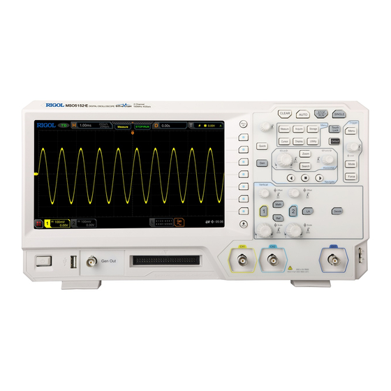
- Page 1 English Quick Guide 中文 MSO5000-E Series Digital Oscilloscope Sept. 2019 RIGOL (SUZHOU) TECHNOLOGIES INC.
-
Page 3: Guaranty And Declaration
RIGOL products are covered by P.R.C. and foreign patents, issued and pending. RIGOL reserves the right to modify or change parts of or all the specifications and pricing policies at the company’s sole decision. Information in this publication replaces all previously released materials. -
Page 4: General Safety Summary
RIGOL General Safety Summary English Only the exclusive power cord Use the proper fuse. designed for the instrument Avoid circuit or wire exposure. and authorized for use within Do not operate the instrument the local country could be with suspected failures. -
Page 5: Care And Cleaning
This manual gives you a quick review about the front and rear panel of MSO5000-E series, the user interface, and the basic operation method. For the latest version of this manual, download it from the official website of RIGOL (www.rigol.com). MSO5000-E Quick Guide... - Page 6 RIGOL Format Conventions in this Manual English The key on the front panel is denoted by the format of "Key Name (Bold) + Text Box" in the manual. For example, Utility denotes the "Utility" key. Menu The menu items are denoted by the format of "Menu Word (Bold) + Character Shading".
-
Page 7: General Inspection
Product Overview The MSO5000-E series is a high-performance digital oscilloscope designed on the basis of the RIGOL UltraVision II technology. It has a 9-inch capacitive touch screen, and integrates 7 instruments into one. With a compact and portable design, it delivers excellent specifications, such as super high sample bandwidth ratio and high memory depth. - Page 8 RIGOL English Figure 1 Front Panel Table 1 Front Panel Description Description Description Capacitive Touch Screen Trigger Control System Function Menu Operation Keys Horizontal Control System Function/Arbitrary Waveform Navigation Control key Generator Setting Key Quick Key (Shortcut Key) Vertical Control System...
- Page 9 RIGOL English Figure 2 Rear Panel Table 2 Rear Panel Description Description Handle Trigger Output Interface LAN Interface USB DEVICE Interface HDMI Video Output AC Power Cord Connector Kensington Security Lock Hole MSO5000-E Quick Guide...
- Page 10 RIGOL English 5 6 7 10 11 12 21 20 14 13 Figure 3 User Interface Table 3 User Interface Icons Description Description Analog Channel Label and Waveform Trigger Level/Threshold Level Operating Status Operation Menu Horizontal Time Base Notification Area...
-
Page 11: To Prepare For Use
RIGOL To Prepare for Use English To Adjust the Supporting Legs You can unfold the supporting legs to use them as stands to tilt the instrument upwards for easier operation and observation, as shown in Figure 4. You can also fold the supporting legs for easier storage or shipment when the instrument is not in use. -
Page 12: Turn-On Checkout
Utility Language to set the system language. You can also enable the touch screen to perform the above menu operation. To Connect the Probe RIGOL provides the passive probe and the logic probe for MSO5000-E series. MSO5000-E Series Datasheet For specific probe models, please refer to . - Page 13 Figure 7. Connect the other terminal of the logic probe to the signal terminal under test. RIGOL's MSO5000-E series supplies PLA2216 active logic probe option. To apply to different application scenarios, PLA2216 provides two connection methods to connect the signal under test. For details, refer to...
-
Page 14: Function Inspection
RIGOL Note: The digital channel input terminal does not support hot plugging. Please English do not insert or pull out the logic probe when the instrument is in power-on state. Function Inspection Press Default on the front panel, and then a prompt message "Restore default?"... -
Page 15: Probe Compensation
RIGOL English Figure 9 Square Waveform Signal Use the same method to test the other channels. If the square waveforms actually shown do not match that in the figure above, please perform relevant procedures specified in "Probe Compensation". WARNING To avoid electric shock when using the probe, please make sure that the insulated wire of the probe is in good condition. -
Page 16: Touch Screen Operation
RIGOL English Perform Step 1, 2, 3 and 4 specified in "Function Inspection". Check the displayed waveforms and compare them with waveforms in Figure 10. Over compensated Perfectly compensated Under compensated Figure 10 Probe Compensation Use the adjustment tool to adjust the low-frequency compensation adjustment hole on the probe until the waveform is displayed as "Perfectly... - Page 17 RIGOL Tap the virtual keypad to set the label name and the filename. English Tap close button at the upper-right corner of the message box to close it. Tap and operate the windows on the screen. Figure 11 Tap Gesture Pinch&Stretch...
-
Page 18: Rectangle Drawing
RIGOL English Figure 13 Drag Gesture Rectangle Drawing Enable the function navigation, and then tap the "Draw rect" icon to switch to the rectangle drawing mode. Drag to draw a rectangle on the screen, as shown in Figure 14. The actions supported by the rectangle drawing include: Select "Trigger zone A":... -
Page 19: To Use The Built-In Help System
RIGOL English Figure 14 Rectangle Drawing Gesture To Use the Built-in Help System The help system of this oscilloscope provides instructions for all the function keys on the front panel and their corresponding menu keys. The steps for opening the built-in help system are as follows: Press Utility ... - Page 20 RIGOL After opening the help interface, you can get its help information in the "Help English Display Area" through the following three methods: Method 1: For the keys, you can directly press the front-panel keys (except the Power key , the Menu off key and Back key) to obtain the corresponding help information.
-
Page 21: Parameter Setting Method
RIGOL Parameter Setting Method English For the MSO5000-E series, you can use the multifunction knob or enable the touch screen to set the parameters of MSO5000-E series. The common parameter setting methods are as follows: Method 1: For the parameters with the sign... - Page 22 RIGOL values, you can also press OK directly to close the numeric keypad. At this time, English the unit of the parameter is the default unit. In the numeric keypad, you can also perform the following operations: Delete the parameter value that has been input.
-
Page 23: Remote Control
For more information about this instrument, refer to the relevant manuals by logging in to the official website of RIGOL (www.rigol.com) to download them. MSO5000-E User Guide : introduces the functions of the instrument and the operation methods, remote control methods, possible failures and solutions in using the instrument, the technical specifications, and order information. - Page 25 快速指南 中文 MSO5000-E 系列数字示波器 2019 年 9 月 RIGOL (SUZHOU) TECHNOLOGIES INC.
- Page 27 商标信息 RIGOL 是苏州普源精电科技有限公司的注册商标。 文档编号 QGA28001-1110 声明 本公司产品受中国及其他国家和地区的专利(包括已取得的和正在申请的 专利)保护。 本公司保留改变规格及价格的权利。 本手册提供的信息取代以往出版的所有资料。 本手册提供的信息如有变更,恕不另行通知。 对于本手册可能包含的错误,或因手册所提供的信息及演绎的功能以及因 使用本手册而导致的任何偶然或继发的损失,RIGOL 概不负责。 未经 RIGOL 事先书面许可,不得影印、复制或改编本手册的任何部分。 产品认证 RIGOL 认证本产品符合中国国家产品标准和行业产品标准及 ISO9001:2015 标 准和 ISO14001:2015 标准,并进一步认证本产品符合其他国际标准组织成员的 相关标准。 联系我们 如您在使用此产品或本手册的过程中有任何问题或需求,可与 RIGOL 联系: 电子邮箱:service@rigol.com 网址:www.rigol.com MSO5000-E 快速指南...
- Page 28 RIGOL 一般安全概要 请使用所在国家认可的本产品 怀疑产品出故障时,请勿进行操 专用电源线。 作。 10. 请保持适当的通风。 请确保产品可靠接地。 11. 请勿在潮湿环境下操作。 查看所有终端额定值。 中文 12. 请勿在易燃易爆的环境下操作。 请使用合适的过压保护。 13. 请保持产品表面的清洁和干燥。 请勿开盖操作。 14. 请注意防静电保护。 请勿将异物插入排风口。 15. 请注意搬运安全。 请使用合适的保险丝。 避免电路外露。 安全术语和符号 本手册中的安全术语: 警告 警告性声明指出可能会造成人身伤害或危及生命安全的情况或操 作。 注意 注意性声明指出可能导致本产品损坏或数据丢失的情况或操作。 产品上的安全术语: DANGER 表示您如果不进行此操作,可能会立即对您造成危害。 WARNING 表示您如果不进行此操作,可能会对您造成潜在的危害。 CAUTION 表示您如果不进行此操作,可能会对本产品或连接到本产品...
- Page 29 物通过散热孔进入机箱内。清洁带有液晶显示屏的仪器时,请注意不要划 伤液晶显示屏。 注意 请勿使任何腐蚀性的液体沾到仪器上,以免损坏仪器。 警告 重新通电之前,请确认仪器已经干透,避免因水分造成电气短路甚 至人身伤害。 文档概述 本文档用于指导用户快速了解MSO5000-E系列数字示波器的前后面板、 用户界面 及基本操作方法等。 提示 本手册的最新版本可登陆 RIGOL 网址(www.rigol.com)进行下载。 文档格式的约定 按键 用 “按键字符 (加粗) +文本框” 表示前面板按键, 如 Utility 表示 “Utility” 按键。 菜单 用 “菜单文字 (加粗) +字符底纹” 表示一个菜单选项, 如 系统 表示 Utility 按键下的“系统”菜单选项。 MSO5000-E 快速指南...
- Page 30 RIGOL 操作步骤 用箭头“”表示下一步操作,如 Utility 系统 表示按下前面板上的 Utility 按键后,再按 系统 菜单键。 4. 旋钮 中文 标识 旋钮 标识 旋钮 水平时基旋钮 垂直档位旋钮 SCALE SCALE 水平 垂直 水平位移旋钮 垂直偏移旋钮 POSITION OFFSET 水平 垂直 触发电平旋钮 多功能旋钮 LEVEL 触发 文档内容的约定 MSO5000-E系列数字示波器包含以下型号。 如无特殊说明, 本手册以MSO5152-E 为例说明MSO5000-E系列及其基本操作。 函数/任意波形...
- Page 31 中文 因运输造成仪器损坏,由发货方和承运方联系赔偿事宜。RIGOL公司恕不 进行免费维修或更换。 2. 检查整机 若存在机械损坏或缺失,或者仪器未通过电性和机械测试,请联系您的 RIGOL 经销商。 3. 检查随机附件 请根据装箱单检查随机附件, 如有损坏或缺失, 请联系您的RIGOL经销商。 产品简介 MSO5000-E 系列数字示波器是基于 RIGOL UltraVision II 代技术的高性能数字 示波器,采用 9 英寸多点电容触摸屏,集 7 种仪器于一身。具有超高的采样带宽 比和存储深度等优异的性能指标,以及精巧便携的外观设计。同时,全系列均支 持通道数、带宽、仪器功能组合和分析功能的软件升级,并可根据不同用户群体 的需求量身定制,从而最大程度帮助用户节省预算,使用户享受最优地测试支持 与使用体验。 前面板、后面板和主界面(显示屏)的简要介绍请分别参考图 1(具体说明见表 1) 、图 2(具体说明见表 2)和图 3(具体说明见表 3) 。 MSO5000-E 快速指南...
- Page 32 RIGOL 中文 图 1 前面板 表 1 前面板说明 编号 说明 编号 说明 电容触摸屏 触发控制系统 功能菜单操作键 水平控制系统 函数/任意波形发生器设 导航控制键 置键 Quick 快捷键 垂直控制系统 多功能旋钮 探头补偿信号输出端/接地端 常用操作键 外触发输入 全部清除键 模拟通道输入 波形自动显示键 数字通道输入 函数/任意波形发生器输出端 运行/停止控制键 USB HOST 接口 单次触发控制键 触摸屏锁定键 电源键 默认设置键 ——...
- Page 33 RIGOL 中文 图 2 后面板 表 2 后面板说明 编号 说明 手柄 触发输出接口 LAN 接口 USB DEVICE 接口 HDMI 高清视频输出 AC 电源插孔 Kensington 安全锁孔 MSO5000-E 快速指南...
- Page 34 RIGOL 5 6 7 10 11 12 中文 21 20 14 13 图 3 用户界面 表 3 用户界面标识 编号 说明 编号 说明 模拟通道标签和波形 操作菜单 运行状态 通知区域 水平时基 采样率和存储深度 任意波发生器波形标签 自动测量标签 数字通道状态区 波形存储器 触发位置 消息框 运行/停止控制标识 CH2 状态标签 水平位移 CH1 状态标签...
- Page 35 RIGOL 使用前准备 调节支撑脚 打开支撑脚,将其作为支架使示波器向上倾斜,便于更好的操作和观察显示屏, 中文 如图 4 所示。在不使用仪器时,用户可以合上支撑脚以方便放置或搬运。 支撑脚打开 支撑脚合上 图 4 调节支撑脚 连接电源 本示波器可输入交流电源的规格为:100~240 V,45~440 Hz。请使用附件提供 的电源线按图 5 所示将示波器连接到电源中。 电源插孔 图 5 连接电源 MSO5000-E 快速指南...
- Page 36 RIGOL 开机检查 当示波器处于通电状态时,按前面板左下角的电源键 即可启动示波器。开 机过程中示波器执行一系列自检,自检结束后出现开机画面。 设置系统语言 中文 MSO5000-E 系列示波器支持多种系统语言, 您可以按 Utility Language 设 置系统语言。上述菜单操作,您也可以通过触摸屏功能实现。 连接探头 RIGOL 为 MSO5000-E 系列提供无源探头和逻辑探头。探头的具体型号请参考 《MSO5000-E 系列数据手册》 。 有关探头的详细技术信息请参考相应的探头用户 手册。 连接无源探头: 将探头的 BNC 端连接至示波器前面板的模拟通道输入端,如图 6 所示。 将探头接地鳄鱼夹或接地弹簧连接至电路接地端,然后将探针连接至待测 电路测试点中。 图 6 连接无源探头 连接无源探头后,您需要在测量前进行探头功能检查和探头补偿调节,具体步骤 请参考本手册中“功能检查”和“探头补偿”介绍的内容。 连接逻辑探头: 关闭待测设备的电源。...
- Page 37 RIGOL 将逻辑探头输出端按正确的方向连接至示波器前面板的数字通道输入端, 如 图 7 所示。 将逻辑探头另一端连接至待测信号端。 RIGOL 为 MSO5000-E 提供 PLA2216 有源逻辑探头选件。 为适应不同的应用场合, PLA2216 提供了两种连接被测 信号的方法,具体请参考《PLA2216 有源逻辑探头用户手册》 。 中文 图 7 连接逻辑探头 注意:数字通道输入接口不支持热插拔,请勿在仪器带电的情况下插入或拔出逻 辑探头。 功能检查 按示波器前面板 Default 键,屏幕弹出“确定恢复默认设置?”提示框, 按 确定 键或用触摸手势点击“确定”选项将示波器恢复为出厂默认配置。 将探头的接地鳄鱼夹连接至图 8 所示的“接地端” 。 使用探头连接示波器的通道 1(CH1)输入端和图 8 所示的“补偿信号输出...
- Page 38 RIGOL 观察示波器显示屏上的波形,正常情况下应显示图 9 所示的方波信号。 中文 图 9 方波信号 用同样方法检查其他通道。如实际显示的方波形状与上图不相符,请执行 “探头补偿”一节介绍的内容。 警告 为避免使用探头时被电击,请首先确保探头的绝缘导线完好,并 且在连接高压源时不要接触探头的金属部分。 提示 探头补偿连接器上输出的信号仅作探头补偿调整之用,不可用于校准。 探头补偿 首次使用探头时,应进行探头补偿调节,使探头与示波器输入通道匹配。未经补 偿或补偿偏差的探头会导致测量误差或错误。探头补偿步骤如下: 执行上一节“功能检查”介绍中的步骤 1、2、3 和 4。 检查所显示的波形形状并与图 10 所得波形进行对比。 MSO5000-E 快速指南...
- Page 39 RIGOL 补偿过度 补偿正确 补偿不足 中文 图 10 探头补偿 使用附件中提供的探头补偿调节棒调整探头上的低频补偿调节孔,直到显 示的波形如上图 10 所示的“补偿正确” 。 触摸屏操作 MSO5000-E 系列提供 9 英寸超大电容触摸屏,支持多点触控和手势操作,兼顾 了强大的波形显示能力及优异的用户体验,具有简捷方便、灵活和高灵敏度等特 点。触摸屏控件支持的功能包括触摸、捏合、拖动和矩形绘制。 提示 本示波器屏幕上显示的菜单及屏幕上可使能的标签按钮均可以使用触摸屏功能。 触摸 用一个手指轻轻点碰屏幕上的图符或文字,如图 11 所示。触摸可实现的功能包 括: 触摸屏幕上显示的菜单,可对菜单进行操作。 触摸屏幕左下角的功能导航图标 ,可打开功能导航。 触摸弹出的数字键盘,可对参数进行设置。 触摸虚拟键盘,设置标签名和文件名。 触摸信息弹出框右上角的关闭按钮,关闭弹出框。 触摸屏幕上显示的其他窗口,对窗口进行操作。...
- Page 40 RIGOL 中文 图 11 触摸手势 捏合 将两根手指靠拢在一起或分开。捏合手势可放大或缩小相关波形。需放大时,先 将两根手指先靠拢在一起,然后滑动分开;需缩小时,先将两根手指分开,然后 滑动在一起,如图 12 所示。捏合可实现的功能包括: 水平方向捏合可调整波形的水平时基。 垂直方向捏合可调整波形的垂直档位。 图 12 捏合手势 拖动 用单指按住拖动目标不放,然后将其拖至目标位置,如图 13 所示。拖动可实现 的功能包括: 拖动波形以改变波形位移或偏移。 拖动窗口控件以改变窗口位置(如数字键盘) 。 拖动光标以改变光标位置。 MSO5000-E 快速指南...
- Page 41 RIGOL 中文 图 13 拖动手势 矩形绘制 打开功能导航,然后点击“矩形绘制”图标,切换为矩形绘制模式,在屏幕上拖 动手指以绘制矩形,如图 14 所示。矩形绘制可实现的功能包括: 选择“区域触发 A” : 绘制区域触发 A 的区域; 打开区域触发 A; 打开“区域触发”菜单。 选择“区域触发 B” : 绘制区域触发 B 的区域; 打开区域触发 B; 打开“区域触发”菜单。 选择“直方图” : ...
- Page 42 RIGOL 使用内置帮助系统 本示波器的帮助系统提供了前面板各功能按键及相应菜单键的说明。 打开帮助系 统的步骤如下: 按 Utility 系统 帮助,进入“帮助”功能菜单。您也可以使用触摸 中文 屏功能,点击屏幕左下角的功能导航图标 ,然后点击“帮助”图标进入 “帮助”功能菜单。 按 查看帮助 键,屏幕弹出帮助界面,如图 15 所示。帮助界面主要分两部 分,左边为“帮助选项” ,右边为“帮助显示区” 。 帮助选项 帮助显示区 图 15 帮助信息 打开帮助界面后,您可以通过以下三种方法在帮助显示区中获得相应的帮助信 息: 方法一: 对于按键,您可以直接按仪器前面板上的按键获取相应的帮助信息(电源键 、Menu off 键、Back 键除外) 。 对于旋钮, 您可以旋转旋钮或按下旋钮获取相应的帮助信息 (多功能旋钮...
- Page 43 RIGOL 方法三: 使用触摸屏功能,通过触摸手势直接点击所需的帮助选项获取帮助信息。 提示 其他按键和旋钮帮助信息: 中文 电源键 :电源开/关键。 Menu off 键:菜单隐藏键,按此键可隐藏菜单。 Back 键:菜单返回键,按此键可返回上一级菜单或返回前一次 设置的功能菜单。 多功能旋钮 : 非菜单操作时, 转动该旋钮可调整波形显示的亮 度。菜单操作时,对于含有多个参数选项的菜单项,按下相应的 菜单软键后,旋转该旋钮选择参数项然后再按下该旋钮选中(有 时旋转该旋钮即可选中指定的参数项) 。 该旋钮还可以用于修改参 数、输入文件名等。 若菜单项置灰,您无法直接按前面板相应的菜单键获取相应的帮助信 息,您只能通过上述介绍的方法二或方法三获取帮助信息。 参数设置方法 MSO5000-E 系列的参数设置主要支持多功能旋钮和触摸屏两种输入方式,常用 的参数设置方法如下: 方法一: 对于菜单上显示 的参数,直接旋转前面板上的多功能旋钮 即可选择参...
- Page 44 RIGOL 参数输入框 删除键 最大值键 最小值键 中文 默认值键 清零键 图 16 数字键盘 在数字键盘中, 您可以旋转多功能旋钮 进行选择然后再按下该旋钮选中即可 输入该数值或单位,或者使用触摸屏功能,通过触摸手势点击数字键盘中的数值 或单位进行输入。输入全部数值并选择所需的单位后,数字键盘自动关闭,则完 成参数设置。另外,完成数值输入后,您也可以直接点击数字键盘中的“OK” 键关闭数字键盘,此时参数的单位为默认单位。在数字键盘中,您还可以进行以 下操作: 删除已输入参数数值。 将参数设置为最大值或最小值(有时特指当前状态下的最大值或最小值) 。 将参数设置为默认值。 清空参数输入框。 方法四: 对于菜单上无图标显示的参数, 直接按相应的菜单软键即可切换设置所需的参数 (此方法适用于只有两个可选选项的参数) 。 提示 上述方法是示波器常用的参数设置方法,若某些参数有其他设置方法,将 在本产品用户手册的相关章节中详细介绍。 MSO5000-E 快速指南...
- Page 45 RIGOL 远程控制 MSO5000-E 系列数字示波器支持通过 USB 接口、LAN 接口和 GPIB 接口与计算 机进行通信从而实现远程控制。远程控制基于 SCPI(Standard Commands for Programmable Instruments)命令集实现。MSO5000-E 系列数字示波器支持三 种远程控制方式:用户自定义编程、使用 PC 软件(如 RIGOL Ultra Sigma)和 中文 Web Control 控制。 更多产品信息 获取设备信息 按 Utility 系统 关于此示波器,您可获取设备信息,包括厂商、产 品型号、产品序列号和硬件版本号等。您也可以参考本手册中的“使用内 置帮助系统”内容打开“帮助”功能菜单,然后按 关于此示波器 键获取 设备信息。上述菜单操作,您也可以通过触摸屏功能实现。 查看选件信息及选件安装...
Need help?
Do you have a question about the MSO5152E and is the answer not in the manual?
Questions and answers