Table of Contents
Advertisement
Quick Links
Advertisement
Table of Contents

Related Manuals for AXIOMTEK eBOX100-312-FL Series


Summary of Contents for AXIOMTEK eBOX100-312-FL Series
- Page 1 Series Embedded System User’s Manual...
-
Page 2: Disclaimers
Axiomtek does not make any commitment to update any information in this manual. Axiomtek reserves the right to change or revise this document and/or product at any time without notice. No part of this document may be reproduced, stored in a retrieval system, or transmitted in any forms or by any means, electronic, mechanical, photocopying, recording, among others, without prior written permissions of Axiomtek Co., Ltd. -
Page 3: Safety Precautions
Safety Precautions Before getting started, please read the following important safety precautions. The eBOX100-312-FL does not come with an operating system which must be loaded first before installation of any software into the computer. Be sure to ground yourself to prevent static charge when installing any internal components. -
Page 4: Classifications
Classifications Degree of production against electric shock: not classified Degree of protection against ingress of water: IP40 Equipment not suitable for use in the presence of a flammable anesthetic mixture with air, oxygen or nitrous oxide. Mode of operation: Continuous... -
Page 5: General Cleaning Tips
General Cleaning Tips Please keep the following precautions in mind while understanding the details fully before and during any cleaning of the computer and any components within. A piece of dry cloth is ideal to clean the device. Be cautious of any tiny removable components when using a vacuum cleaner to absorb dirt on the floor. -
Page 6: Scrap Computer Recycling
Scrap Computer Recycling Please inform the nearest Axiomtek distributor as soon as possible for suitable solutions in case computers require maintenance or repair; or for recycling in case computers are out of order. Trademarks Acknowledgments Axiomtek is a trademark of Axiomtek Co., Ltd. -
Page 7: Table Of Contents
Table of Contents Disclaimers ......................ii Safety Precautions ....................iii Classifications ....................... iv General Cleaning Tips ................... v Scrap Computer Recycling ................... vi SECTION 1 INTRODUCTION .................. 1 General Descriptions ................. 1 System Specifications ............... 2 1.2.1 CPU ........................2 1.2.2 I/O System ...................... - Page 8 Main Menu ..................32 Advanced Menu ................33 Chipset Menu ................... 42 Security Menu .................. 46 Save & Exit Menu ................48 APPENDIX A WATCHDOG TIMER ..............51 About Watchdog Timer .................. 51 Sample Program ....................52 viii...
-
Page 9: Section 1 Introduction
Series user’s Manual SECTION 1 INTRODUCTION This section contains general information and detailed specifications of the eBOX100-312-FL.Section 1 consist of the following sub-sections: General Descriptions System Specifications Dimensions I/O Outlets Packing List Model List 1.1 General Descriptions... -
Page 10: System Specifications
Series user’s Manual Features ® ® Intel Celeron processor N3350 dual core, up to 2.4 GHz with turbo boost ® ® Intel Pentium processor N4200 quad core, up to 2.5 GHz 1 COM port, 6 USB ports and 2 GbE LANs ... -
Page 11: I/O System
Series user’s Manual 1.2.2 I/O System Display 2 x HDMI (HDMI 1.4b up to 3840 x 2160@30Hz) Ethernet 2 x 10/100/1000 Ethernet ports (i211AT) USB Ports 4 x USB 2.0 2 x USB 3.0 ... -
Page 12: System Specifications
Series user’s Manual 1.2.3 System Specifications Watchdog Timer 1~255 seconds or minutes; up to 255 levels. Power Supply 12VDC /36W AC to DC adapter Operation Temperature -5℃ ~+60℃ (23 ºF ~ 140ºF), with W .T. SSD & Memory ... -
Page 13: Dimensions
Series user’s Manual 1.3 Dimensions The following diagrams show dimensions and outlines of the eBOX100-312-FL. 1.3.1 System Dimensions Introduction... -
Page 14: Wall-Mount Bracket Dimensions (A)
Series user’s Manual 1.3.2 Wall-mount Bracket Dimensions (A) Instruction Step 1: Before install the wall mount kit, please remove the four foot pads, and screw the two pieces of wall-mount kits to the bottom plate of the device. Total four screws (metric 3 x6) are required. - Page 15 Series user’s Manual 1.3.3 Wall-mount Bracket Dimensions (B) Instruction Step 1: Before install the wall mount kit, please remove the four foot pads, and screw the two pieces of wall-mount kits to the bottom plate of the device. Total four screws (metric 3 x6) are required.
- Page 16 Series user’s Manual 1.3.4 Din-Rail kit Dimensions Instruction Step 1: Screw the Din rail mount Bracket to the bottom plate of the device. Total of four screws (Flat Head M3 x4) are required. Step 2: Users can install the eBOX100 in din-rail bracket through din-rail bracket kit.
- Page 17 Series user’s Manual 1.3.5 VESA Mount Dimensions Instruction Step 1: Please refer to above photo to screw the VESA mount bracket kit with the bottom plate of the device. Total four screws (metric 4 x6) are required. Step 2: Insert four screws into the VESA hole of monitor and reserved a gap about 1.2~1.5mm.
-
Page 18: I/O Outlets
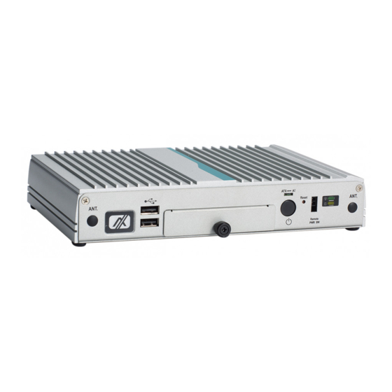
Series user’s Manual 1.4 I/O Outlets The following figures show I/O outlets on the eBOX100-312-FL. Front View Rear View 2 x USB 2.0 ATX/AT quick switch 1 x swappable HDD drive bay 12VDC power input 1 x Power button... -
Page 19: Packing List
Series user’s Manual 1.5 Packing List The eBOX100-312-FL comes with the following bundle package: eBOX100-312-FL System Unit x 1 Quick Installation Guide x 1 DVD x 1 (For Driver and Manual) HDD Screw x 1 ... -
Page 20: Model List
GHz,2 HDMI, 2 GbE LANs and 6 USB (w/o adapter and power cord) ® ® Fan-less embedded system with Intel Pentium N4200 2.5 eBOX100-312-FL-DC-N4200 GHz,2 HDMI, 2 GbE LANs and 6 USB (w/o adapter and power cord) Please contact Axiomtek’s distributors immediately in case any abovementioned items are missing. Introduction... -
Page 21: Section 2 Hardware Installation
Series user’s Manual SECTION 2 HARDWARE INSTALLATION The eBOX100-312-FL is convenient for various hardware configurations, such as CPU, DRAM, HDD (Hard Disk Drive), SSD (Solid State Drive) and PCI Express Mini card modules. Section 2 contains guidelines for hardware installation. - Page 22 Series user’s Manual Step 5 Before assemble the SSD/HDD, please loosen the thumb screw to remove the HDD bracket, and then assemble the SSD/HDD with the one HDD mounting screw. Step 6 Put the bottom cover back and fasten all the screws.
-
Page 23: Installation Of So-Dimm
Series user’s Manual 2.2 Installation of SO-DIMM Step 1 Turn off the system and unplug the power cord. Step 2 Turn the system upside down to locate screws at the bott om and then loosen all screws. Step 3 Located the SO-DIMM socket on main board. -
Page 24: Installation Of Mini Pcie Module (Full-Size)
Series user’s Manual 2.3 Installation of Mini PCIe Module (full-size) Step 1 Turn off the system and unplug the power cord. Step 2 Turn the system upside down to locate screws at the bottom, and then loosen all screws. -
Page 25: Section 3 Jumper & Connector Settings
Series user’s Manual SECTION 3 JUMPER & CONNECTOR SETTINGS Proper jumper settings configure the eBOX100-312-FL to meet various application needs. Hereby all jumpers settings along with their default settings are listed for devices onboard. 3.1 Locations of Jumpers & Connectors SBC87312 Top View Jumper &... - Page 26 Series user’s Manual SBC87312 Bottom View 【Note】: It is strongly recommended that any unmentioned jumper settings should not be modified without instructions by Axiomtek FAEs. Any modifications without instructions might cause system failure. Jumper & Connector Settings...
-
Page 27: Summary Of Jumper Settings
Series user’s Manual 3.2 Summary of Jumper Settings Proper jumper settings configure the eBOX100-312-FL to meet various application purposes. A table of all jumpers and their default settings is listed below. Jumper and Switch Descriptions Settings Restore BIOS Optimal Defaults... -
Page 28: Restore Bios Optimal Defaults (Jp2)
Series user’s Manual 3.2.1 Restore BIOS Optimal Defaults (JP2) Put jumper clip to pin 2-3 for a few seconds then move it back to pin 1 -2. This procedure is to restore BIOS optimal defaults. Functions Settings Normal (Default) -
Page 29: Connectors
Series user’s Manual 3.3 Connectors Please refer to pin assignments below: External Connectors Sections DC Power Jack 3.3.1 COM1 Connector 3.3.2 HDMI Connector 3.3.3 Ethernet Connector 1 and 2 3.3.4 ATX Power On/Off Button 3.3.5 Reset Button 3.3.6 Remote Power Switch Connector 3.3.7... -
Page 30: Dc Power Jack Connector (Screw Type)
Series user’s Manual 3.3.1 DC Power Jack Connector (screw type) The system supports 12V DC-in connector for system power input. The CN12 is a DC jack with screw. Firmly insert at least 36W adapter into this connector. Loose connection may... -
Page 31: Hdmi Connector
Series user’s Manual 3.3.3 HDMI Connector The HDMI (High-Definition Multimedia Interface) is a compact digital interface which is capable of transmitting high-definition video and high-resolution audio over a single cable. Pins Signals Pins Signals HDMI OUT_DATA2+ HDMI OUT_DATA2- HDMI OUT_DATA1+... -
Page 32: Ethernet Ports (Lan1 And Lan2)
Series user’s Manual 3.3.4 Ethernet Ports (LAN1 and LAN2) The system has two RJ-45 connectors: LAN1 and LAN2. Ethernet connection can be established by plugging one end of the Ethernet cable into this RJ-45 connector and the other end (phone jack) to a 1000/100/10-Base-T hub. -
Page 33: Reset Button
Series user’s Manual 3.3.6 Reset button The Reset button can allow users to reset eBOX100-312-FL during system abnormal situation. Functions Descriptions Reset system Keep system status 3.3.7 Remote Power Switch Connector One 2-pin connector output for remote power on/off switch. -
Page 34: Usb 3.0 Port (Usb 1)
Series user’s Manual 3.3.9 USB 3.0 Port (USB 1) The Universal Serial Bus (compliant with USB 3.0 (5Gb/s)) connector on the rear I/O is for installing USB peripherals such as keyboard, mouse, scanner, etc. USB 3.0 port 1 and 2:... -
Page 35: Sata/Sata Power Connector (Sata 1)
Series user’s Manual 3.3.10 SATA/SATA Power connector (SATA 1) SATA1 connector supports one 2.5" HDD/SSD. Pins Signals Pins Signals +3.3V SATA0_TX+ +3.3V SATA0_TX- +3.3V SATA0_RX- SATA0_RX+ Jumper & Connector Settings... -
Page 36: Full-Size Pci-Express Mini Card Connector (Cn4/Cn6)
Series user’s Manual 3.3.11 Full-size PCI-Express Mini Card Connector (CN4/CN6) This is a full-size PCI-Express Mini Card connector on the bottom side supporting PCI- Express x1 or USB 2.0. It also complies with PCI-Express Mini Card Spec. V1.2. Pins... -
Page 37: Sim Card Slot (Cn5)
Series user’s Manual 3.3.12 SIM Card slot (CN5) This board has CN5 socket on the bottom side for inserting SIM Card. In order to work properly, the SIM Card must be used together with 3G module which is inserted to CN4 or CN6. - Page 38 Series user’s Manual This page is intentionally left blank. Jumper & Connector Settings...
-
Page 39: Section 4 Bios Setup Utility
Series user’s Manual SECTION 4 BIOS SETUP UTILITY This section provides users with detailed descriptions in terms of how to set up basic system configurations through the BIOS setup utility. 4.1 Starting To enter the setup screens, follow the steps below: Turn on the computer and press the <Del>... -
Page 40: Main Menu
Series user’s Manual 4.3 Main Menu The Main Menu screen is the first screen users see when entering the setup utility. Users can always return to the Main setup screen by selecting the Main tab. System Time/Date can be set up as described below. -
Page 41: Advanced Menu
Series user’s Manual 4.4 Advanced Menu The Advanced menu also allows users to set configuration of the CPU and other system devices. Users can select any items in the left frame of the screen to go to sub menus: ►... - Page 42 Series user’s Manual ACPI Settings Use this screen to select options for the ACPI configuration, and change the value of the selected option. A description of the selected item appears on the right side of the screen. ACPI Sleep State When the sleep button is pressed, the system will be in the ACPI sleep state.
- Page 43 Series user’s Manual CPU Configurations This screen shows the CPU version and its detailed information. Intel Virtualization Technology It allows a hardware platform to run multiple operating systems separately and simultaneously, enabling one system to virtually function as several systems.
- Page 44 Series user’s Manual F81803 Super IO Configurations Use this screen to select options for the F81803 Super IO Configurations, and change the value of the selected option. A description of the selected item appears on the right side of the screen.
- Page 45 Series user’s Manual BIOS Setup Utility...
- Page 46 Series user’s Manual Hardware Monitor This screen monitors hardware health status. This screen displays the temperature of system and CPU, system voltages (VCORE, +3.3V, +12V and +5V). BIOS Setup Utility...
- Page 47 Series user’s Manual SATA Configurations In this Configuration menu, you can see the currently installed hardware in the SATA port. During system boot up, the BIOS automatically detects the presence of SATA device. SATA Mode Selection AHCI (Advanced Host Controller Interface) mode is how SATA controller(s) operate.
- Page 48 Series user’s Manual USB Configurations This screen specifies USB settings. USB Devices Display all detected USB devices. Mass Storage Devices Mass storage device emulation type. Auto option enumerates devices according to their media format. Optical drives are emulated as CDROM; drives with no media will be emulated according to a drive type.
- Page 49 Series user’s Manual Utility Configurations This screen is for BIOS flash utility. BIOS Flash Utility BIOS flash utility configuration. BIOS Setup Utility...
-
Page 50: Chipset Menu
Series user’s Manual 4.5 Chipset Menu The Chipset menu allows users to change the advanced chipset settings. Users can select any of the items in the left frame of the screen to go to the sub menus: ► North Bridge ►... - Page 51 Series user’s Manual North Bridge This screen allows users to configure parameters of North Bridge chipset. LCD Control This item allows you to select LCD panel control options. Please press <Enter> to go to the sub menus. Memory Information Display system memory information.
- Page 52 Series user’s Manual GOP / VBIOS In order to avoid the 4K side effect, our system default is GOP mode, if customer would like to use PXE or DOS, please select VBIOS. 【Note】: GOP mode cannot support PXE and DOS.
- Page 53 Series user’s Manual South Bridge This screen shows the information of South Bridge chipset. BIOS Setup Utility...
-
Page 54: Security Menu
Series user’s Manual 4.6 Security Menu Administrator Password This item indicates whether an administrator password has been set (installed or uninstalled). User Password This item indicates whether a user password has been set (installed or uninstalled). BIOS Setup Utility... - Page 55 Series user’s Manual Boot Menu The Boot menu allows users to change boot options of the system. Setup Prompt Timeout Use this item to set up number of seconds to wait for setup activation key where 65535(0xFFFF) means indefinite waiting.
-
Page 56: Save & Exit Menu
Series user’s Manual 4.7 Save & Exit Menu The Save & Exit menu allows users to load system configurations with optimal or fail-safe default values. Save Changes and Exit When users have completed the system configuration changes, select this option to leave Setup and return to Main Menu. - Page 57 Series user’s Manual Save Changes When completed the system configuration changes, select this option to save changes. Select Save Changes from the Save & Exit menu and press <Enter>. Select Yes to save changes. Discard Changes Select this option to quit Setup without making any permanent changes to the system configurations.
- Page 58 Series user’s Manual This page is intentionally left blank. BIOS Setup Utility...
-
Page 59: Appendix Awatchdog Timer
Series user’s Manual APPENDIX A WATCHDOG TIMER About Watchdog Timer Software stability is major issue in most applications. Some embedded systems are not watched by human for 24 hours. It is usually too slow to wait for someone to reboot when computer hangs. -
Page 60: Sample Program
Series user’s Manual Sample Program The following example enables configurations using debug tool. Enable WDT Enable configuration: O 2E 87; Un-lock super I/O O 2E 87 Select logic device: O 2E 07 O 2F 08 WDT device enable:...
Need help?
Do you have a question about the eBOX100-312-FL Series and is the answer not in the manual?
Questions and answers