Table of Contents
Advertisement
Quick Links
Advertisement
Table of Contents

Subscribe to Our Youtube Channel
Related Manuals for AXIOMTEK eBOX560-500-FL Series


Summary of Contents for AXIOMTEK eBOX560-500-FL Series
- Page 1 Series Embedded System User’s Manual...
-
Page 2: Disclaimers
Axiomtek does not make any commitment to update the information in this manual. Axiomtek reserves the right to change or revise this document and/or product at any time without notice. No part of this document may be reproduced, stored in a retrieval system, or transmitted, in any form or by any means, electronic, mechanical, photocopying, recording, or otherwise, without the prior written permission of Axiomtek Co., Ltd. -
Page 3: Safety Precautions
Safety Precautions Before getting started, please read the following important safety precautions. The eBOX560-500-FL does not come equipped with an operating system. An operating system must be loaded first before installing any software into the computer. Be sure to ground yourself to prevent static charge when installing the internal components. -
Page 4: Classification
Classification Degree of production against electric shock : not classified Degree of protection against the ingress of water : IP40 Equipment not suitable for use in the presence of a flammable anesthetic mixture with air or with oxygen or nitrous oxide. Mode of operation : Continuous... -
Page 5: General Cleaning Tips
General Cleaning Tips You may need the following precautions before you begin to clean the computer. When you clean any single part or component for the computer, please read and understand the details below fully. When you need to clean the device, please rub it with a piece of dry cloth. Be cautious of the tiny removable components when you use a vacuum cleaner to absorb the dirt on the floor. -
Page 6: Scrap Computer Recycling
If the computer equipment’s needs the maintenance or are beyond repair, we strongly recommended that you should inform your Axiomtek distributor as soon as possible for the suitable solution. For the computers that are no longer useful or no longer working well, please contact your Axiomtek distributor for recycling and we will make the proper arrangement. -
Page 7: Table Of Contents
Table of Contents Disclaimers ......................ii Safety Precautions ....................iii Classification ......................iv General Cleaning Tips ................... v Scrap Computer Recycling ................... vi CHAPTER 1 INTRODUCTION ............... 1 General Description ................1 System Specifications ............... 2 1.2.1 CPU ........................2 1.2.2 I/O System ...................... - Page 8 Advanced Menu ................29 Chipset Menu ................... 39 Security Menu .................. 46 Boot Menu ..................47 Save & Exit Menu ................48 APPENDIX A WATCHDOG TIMER .............. 51 About Watchdog Timer ................... 51 How to Use Watchdog Timer ................51 Sample Program ....................
-
Page 9: Chapter 1 Introduction
Series User’s Manual CHAPTER 1 INTRODUCTION This chapter contains general information and detailed specifications of the eBOX560-500-FL. The Chapter 1 includes the following sections: General Description System Specifications Dimensions I/O Outlets Packing List ... -
Page 10: System Specifications
Series User’s Manual Supports ATX power button Supports Reset button Two HDMI 10. One 2.5” SATA HDD drive bay 11. One PCI Express Mini Card Slots w/ mSATA supported. 12. Watchdog timer 13. 12V DC power input 14. Two Antenna openings 15. -
Page 11: System Specification
Series User’s Manual 12 VDC Power jack connector Two Indicators LED (System Power, HDD Active) One AT/ATX Quick switch 1.2.3 System Specification Watchdog Timer 1~255 seconds or minutes; up to 255 levels. Power Supply ... -
Page 12: Dimensions
Series User’s Manual Dimensions The following diagrams show you dimensions and outlines of the eBOX560-500-FL. 1.3.1 System Dimension Introduction... -
Page 13: Wall Mount Bracket Dimension
Series User’s Manual 1.3.2 Wall mount Bracket Dimension Instruction Step 1: Screw the two pieces of wall-mount kits to the bottom plate of the device. Total four screws (metric 3 x6) are required. Step 2: Use the device, with wall mount plate attached, as a guide to mark the correct locations of the four screws. -
Page 14: Din-Rail Mount Bracket Dimension
Series User’s Manual 1.3.3 Din-rail mount Bracket Dimension Instruction Step 1: Screw the Din rail mount Bracket to the bottom plate of the device. Total of four screws (metric 3 x6) are required. Step 2: Screw the Din rail bracket (722C9000300E) and the Din rail mount bracket together. -
Page 15: Vesa Mount Bracket Dimension
Series User’s Manual 1.3.4 VESA mount Bracket Dimension Instruction Step 1: Please refer to above photo to screw the VESA mount bracket kit with the bottom plate of the device. Total four screws (metric 3 x6) are required. Step 2: Insert four screws into the VESA hole of monitor and reserved a gap about 1.2~1.5mm. -
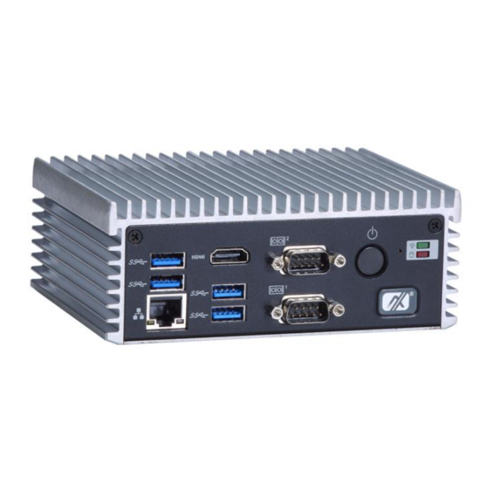
Page 16: I/O Outlets
Series User’s Manual I/O Outlets The following figures show you I/O outlets on front view of the eBOX560-500-FL. Front View drawing Rear View drawing Introduction... -
Page 17: Packing List
Optional Wall-mount kit Optional VESA / DIN-Rail kit Optional Antenna Optional Mini Card module Optional 2.5" SATA Storage Optional mSATA If you cannot find this package or any items are missing, please contact Axiomtek distributors immediately. Introduction... - Page 18 Series User’s Manual This page is intentionally left blank. Introduction...
-
Page 19: Chapter 2 Hardware Installation
Series User’s Manual CHAPTER 2 HARDWARE INSTALLATION The eBOX560-500-FL is convenient for your various hardware configurations, such as HDD (Hard Disk Drive), SSD (Solid State Drive) or PCI Express Mini Card modules. The chapter 2 will show you how to install the hardware. - Page 20 Series User’s Manual Step 6 Fasten total four screws to fix HDD/SSD. ※ Please notice that you should base on the photo to check the direction of HDD. Step 7 Lock the HDD and fasten screws then connect SATA & Power cables.
-
Page 21: Installing The Express Mini Card
Series User’s Manual Installing the Express Mini Card Step 1 Turn off the system, and unplug the power adaptor. Step 2 Turn the system upside down to locate screws at the bottom, loosen screws. Step 3 Remove the HDD bracket then find Mini Card location. - Page 22 Series User’s Manual Step 5 Slide Mini Card into Mini Card slot with caution, and fasten screw of Express Mini Card. Step 6 Assembly the bottom cover back and fasten all screws. Hardware Installation...
-
Page 23: Installing The So-Dimm Memory
Series User’s Manual Installing the SO-DIMM Memory Step 1 Turn off the system, and unplug the power adaptor. Step 2 Turn the system upside down to locate screws at the bottom, loosen screws. Step 3 Please find the HDD bracket location then loosen four screws of HDD bracket to take out it. - Page 24 Series User’s Manual This page is intentionally left blank. Hardware Installation...
-
Page 25: Chapter 3 Jumper Setting & Connector
Series User’s Manual CHAPTER 3 JUMPER SETTING & CONNECTOR Proper jumper settings configure the eBOX560-500-FL to meet your application purpose. We are here with listing a summary table of all jumpers and default settings for onboard devices, respectively. Jumper & Connector Location... - Page 26 Series User’s Manual AX93276 Top Side AX93276 Bottom Side Note: We strongly recommended that you should not modify any unmentioned jumper setting without Axiomtek FAE’s instruction. Any modification without instruction might cause system to become damage. Jumper Setting & Connector...
-
Page 27: Jumper Setting Summary
Series User’s Manual Jumper Setting Summary Proper jumper settings configure the eBOX560-500-FL to meet your application purpose. We are herewith listing a summary table of all jumpers and default settings for onboard devices, respectively. PICO500: Jumper Function/Default Setting Jumper Setting... -
Page 28: At/Atx Quick Switch
Series User’s Manual 3.2.2 AT/ATX Quick Switch If SW1 is enabled for power input, the system will be automatically power on without pressing soft power button. If SW1 is disabled for power input, it is necessary to manually press soft power button to power on the system. -
Page 29: Connectors
Connectors connect the board with other parts of the system. Loose or improper connection might cause problems. Make sure all connectors are properly and firmly connected. Here is a summary table shows you all connectors and button on the eBOX560-500-FL Series. External Connectors / Buttons... -
Page 30: Dc Power Jack W/ Screw (Cn14)
Series User’s Manual 3.3.1 DC Power Jack w/ Screw (CN14) The CN14 is a DC jack with screw. Firmly insert at least 60W adapter into this connector. Loose connection may cause system instability make sure components/devices properly installed before connecting. -
Page 31: Com Serial Port Connector
Series User’s Manual 3.3.4 COM Serial Port Connector The system has two serial ports. COM1 is RS-232/422/485 ports and COM2 is RS-232, please refer to Chapter 4 for the detail of BIOS setting. The lower connector (CN7A) is for COM2 and the upper connector (CN7B) is for COM1. -
Page 32: Usb 3.0 Connector
Series User’s Manual 3.3.5 USB 3.0 Connector The Universal Serial Bus connectors are compliant with USB 3.0 (5Gb/s), and ideally for installing USB peripherals such as keyboard, mouse, scanner, etc. Signal USB Port 0 Signal USB Port 1 USB_VCC (+5V level standby... -
Page 33: System Power Switch
Series User’s Manual 3.3.6 System Power Switch This button is for turning on/off the system power. Function Description Turn on/off system Keep system status 3.3.7 System Reset Switch This button reboots your computer without turning off the power supply. It is a better way to reboot your system for a longer life of the system power supply. -
Page 34: Express Mini Card Slot
Series User’s Manual 3.3.8 Express Mini Card Slot This is a PCI-Express Mini Card connector on the bottom side supporting PCI-Express x1 link and USB 2.0 link. It complies with PCI-Express Mini Card Spec. V1.2. A PCI-Express Mini Card can be applied to either PCI-Express, USB 2.0 or SATA (mSATA). To enable or disable mSATA support, please refer to BIOS setting in section 4.4. -
Page 35: Chapter 4 Bios Setup Utility
Series User’s Manual CHAPTER 4 BIOS SETUP UTILITY This chapter provides users with detailed description how to set up basic system configuration through the BIOS setup utility. Starting To enter the setup screens, follow the steps below: Turn on the computer and press the <Del> key immediately. -
Page 36: Main Menu
Series User’s Manual Main Menu The first time you enter the setup utility, you will enter the Main setup screen. You can always return to the Main setup screen by selecting the Main tab. System Time/Date can be set up as described below. -
Page 37: Advanced Menu
Series User’s Manual Advanced Menu The Advanced menu also allows users to set configuration of the CPU and other system devices. You can select any of the items in the left frame of the screen to go to the sub menus: ►... - Page 38 Series User’s Manual Hardware Monitor This screen monitors hardware health status. BIOS Setup Utility...
- Page 39 Series User’s Manual ACPI Settings You can use this screen to select options for the ACPI configuration, and change the value of the selected option. A description of the selected item appears on the right side of the screen.
- Page 40 Series User’s Manual CPU Configuration This screen shows the CPU information. BIOS Setup Utility...
- Page 41 Series User’s Manual SATA Configuration In this Configuration menu, you can see the currently installed hardware in the SATA ports. During system boot up, the BIOS automatically detects the presence of SATA devices. SATA Mode Selection AHCI (Advanced Host Controller Interface) mode is how SATA controller(s) operate.
- Page 42 Series User’s Manual PCH-HW This screen displays ME Firmware information. BIOS Setup Utility...
- Page 43 Series User’s Manual AMT Configuration Use this screen to configure AMT parameters. Intel AMT Enable or disable Intel Active Management Technology BIOS Extension. ® The default is Enabled. BIOS Setup Utility...
- Page 44 Series User’s Manual USB Configuration USB Devices Display all detected USB devices. BIOS Setup Utility...
- Page 45 Series User’s Manual Intel RC Drivers Version Detail RC driver’s version information. This screen displays Intel ® BIOS Setup Utility...
- Page 46 Series User’s Manual Utility Configuration This screen for Bios flash utility BIOS Flash Utility BIOS flash utility configuration. BIOS Setup Utility...
-
Page 47: Chipset Menu
Series User’s Manual Chipset Menu The Chipset menu allows users to change the advanced chipset settings. You can select any of the items in the left frame of the screen to go to the sub menus: ► PCH-IO Configuration ►... - Page 48 Series User’s Manual PCH-IO Configuration This screen allows you to set PCH parameters. BIOS Setup Utility...
- Page 49 Series User’s Manual HD Audio Configuration Control detection of the HD Audio device. Configuration options are Disabled and Enabled. HD Audio Configuration Use this item for HD Audio configuration settings. BIOS Setup Utility...
- Page 50 Series User’s Manual System Agent (SA) Configuration This screen shows System Agent version information and provides function for specifying related parameters. Graphics Configuration Use this item to configure internal graphics controller. Memory Configuration Use this item to refer to the information related to system memory.
- Page 51 Series User’s Manual Graphics Configuration Primary IGFX Boot Display Select the video device which will be activated during POST (Power-On Self Test). The default is HDMI(ONBOARD).The image above shows option list in Primary IGFX Boot Display when no I/O board is installed.
- Page 52 Series User’s Manual Secondary IGFX Boot Display Select secondary display device. The default is Disabled. BIOS Setup Utility...
- Page 53 Series User’s Manual Memory Information This screen shows the system memory information. BIOS Setup Utility...
-
Page 54: Security Menu
Series User’s Manual Security Menu The Security menu allows users to change the security settings for the system. Administrator Password This item indicates whether an administrator password has been set (installed or uninstalled). User Password This item indicates whether an user password has been set (installed or uninstalled). -
Page 55: Boot Menu
Series User’s Manual Boot Menu The Boot menu allows users to change boot options of the system. Bootup NumLock State Use this item to select the power-on state for the keyboard NumLock. Quiet Boot Select to display either POST output messages or a splash screen during boot-up. -
Page 56: Save & Exit Menu
Series User’s Manual Save & Exit Menu The Save & Exit menu allows users to load your system configuration with optimal or fail-safe default values. Save Changes and Exit When you have completed the system configuration changes, select this option to leave Setup and return to Main Menu. - Page 57 Series User’s Manual Save Changes When you have completed the system configuration changes, select this option to save changes. Select Save Changes from the Save & Exit menu and press <Enter>. Select Yes to save changes. Discard Changes Select this option to quit Setup without making any permanent changes to the system configuration.
- Page 58 Series User’s Manual This page is intentionally left blank. BIOS Setup Utility...
-
Page 59: Appendix A Watchdog Timer
Series User’s Manual APPENDIX A WATCHDOG TIMER About Watchdog Timer Software stability is major issue in most application. Some embedded systems are not watched by human for 24 hours. It is usually too slow to wait for someone to reboot when computer hangs. - Page 60 Series User’s Manual ;Enable WDT: dx,2Eh al,87 ;Un-lock super I/O dx,al dx,al ;Select Logic device: dx,2Eh al,07h dx,al dx,2Fh al,08h dx,al ;Activate WDT: dx,2Eh al,30h dx,al dx,2Fh al,01h dx,al ;Set Second or Minute : dx,2Eh al,0F5h dx,al dx,2Fh Note al,Nh ;N=00h or 08h(see below...
- Page 61 Series User’s Manual Note dx,al ;(see below ;Disable WDT: dx,2Eh al,30h dx,al dx,2Fh al,00h ;Can be disabled at any time dx,al Note: If N=00h, the time base is set to second. M = time value 00: Time-out Disable 01: Time-out occurs after 1 second...
- Page 62 Series User’s Manual This page is intentionally left blank. Watchdog Timer...
Need help?
Do you have a question about the eBOX560-500-FL Series and is the answer not in the manual?
Questions and answers