Table of Contents
Advertisement
Quick Links
Advertisement
Table of Contents

Related Manuals for AXIOMTEK eBOX626-841-FL Series


Summary of Contents for AXIOMTEK eBOX626-841-FL Series
- Page 1 Series Embedded System User’s Manual...
-
Page 2: Disclaimers
Axiomtek does not make any commitment to update the information in this manual. Axiomtek reserves the right to change or revise this document and/or product at any time without notice. No part of this document may be reproduced, stored in a retrieval system, or transmitted, in any form or by any means, electronic, mechanical, photocopying, recording, or otherwise, without the prior written permission of Axiomtek Co., Ltd. -
Page 3: Safety Precautions
Safety Precautions Before getting started, please read the following important safety precautions. The eBOX626-841-FL does not come equipped with an operating system. An operating system must be loaded first before installing any software into the computer. Be sure to ground yourself to prevent static charge when installing the internal components. -
Page 4: Classification
Classification Degree of production against electric shock : not classified Degree of protection against the ingress of water : IP40 Equipment not suitable for use in the presence of a flammable anesthetic mixture with air or with oxygen or nitrous oxide. Mode of operation : Continuous... -
Page 5: General Cleaning Tips
General Cleaning Tips You may need the following precautions before you begin to clean the computer. When you clean any single part or component for the computer, please read and understand the details below fully. When you need to clean the device, please rub it with a piece of dry cloth. Be cautious of the tiny removable components when you use a vacuum cleaner to absorb the dirt on the floor. -
Page 6: Scrap Computer Recycling
If the computer equipment’s needs the maintenance or are beyond repair, we strongly recommended that you should inform your Axiomtek distributor as soon as possible for the suitable solution. For the computers that are no longer useful or no longer working well, please contact your Axiomtek distributor for recycling and we will make the proper arrangement. -
Page 7: Table Of Contents
Table of Contents Disclaimers ........................ ii Safety Precautions ....................iii Classification ......................iv General Cleaning Tips ....................v Scrap Computer Recycling ..................vi CHAPTER 1 INTRODUCTION ................. 1 General Description ................1 System Specifications ................. 2 1.2.1 CPU ........................2 1.2.2 I/O System ...................... - Page 8 CHAPTER 4 BIOS SETUP UTILITY ..............28 Starting ....................28 Navigation Keys .................. 28 Main Menu ................... 29 Advanced Menu .................. 30 Chipset Menu ..................40 Boot Menu ................... 43 Security Menu ..................44 Save & Exit Menu ................45 APPENDIX A WATCHDOG TIMER ..............
-
Page 9: Chapter 1 Introduction
Series User’s Manual CHAPTER 1 INTRODUCTION This chapter contains general information and detailed specifications of the eBOX626-841-FL. The Chapter 1 includes the following sections: General Description System Specification Dimensions I/O Outlets Packing List Model List ... -
Page 10: System Specifications
Series User’s Manual System Specifications 1.2.1 CPU ® Intel Atom dual core E3826 1.46GHz. BIOS American Megatrends Inc. UEFI BIOS. (Unified Extensible Firmware Interface) 16Mbit SPI Flash, DMI, Plug and Play. PXE Ethernet Boot ROM. -
Page 11: Driver Cd Content
Series User’s Manual 1.2.4 Driver CD Content Driver Audio Chipset Ethernet Graphic Manual User Manual Quick Manual NOTE: All specifications and images are subject to change without notice. Introduction... -
Page 12: Dimensions
Series User’s Manual Dimensions The following diagrams show you dimensions and outlines of the eBOX626-841-FL. 1.3.1 System Dimension Introduction... -
Page 13: Wall Mount Bracket Dimension
Series User’s Manual 1.3.2 Wall mount Bracket Dimension Introduction... -
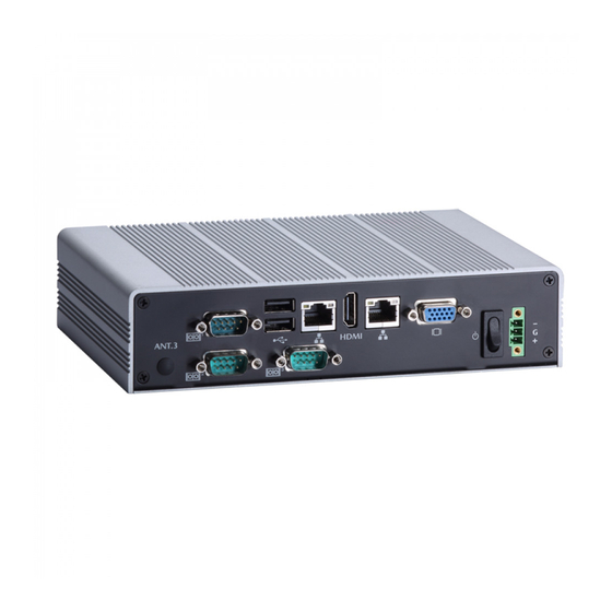
Page 14: I/O Outlets
Series User’s Manual I/O Outlets The following figures show you I/O outlets on front view of the eBOX626-841-FL. Front View Front View drawing Introduction... - Page 15 Series User’s Manual Rear View Rear View drawing Introduction...
-
Page 16: Packing List
(optional) DDR3L SODIMM (optional) WIFI/ 3G/ GPS Modules (optional) If you cannot find this package or any items are missing, please contact Axiomtek distributors immediately. Model List Fanless embedded system with Intel® ATOM® E3826 eBOX626-841-FL-E3826-1.46G -DC single chip design 1.46GHz dual core... -
Page 17: Chapter 2 Hardware Installation
Series User’s Manual CHAPTER 2 HARDWARE INSTALLATION The eBOX626-841-FL is convenient for your various hardware configurations, such as Memory Module, HDD (Hard Disk Drive), SSD (Solid State Drive) and mSATA. The chapter 2 will show you how to install the hardware. - Page 18 Series User’s Manual Step 5 Locate the memory module, insert the gold colored of memory to contact into the socket. Step 6 Push the module down, until it is firmly seated by locking two latches on the sides. Step 7 Fasten all screws of bottom cover to finish installation.
-
Page 19: Installing The 2.5" Sata Hdd/Ssd
Series User’s Manual Installing the 2.5” SATA HDD/SSD Step 1 Turn off the system, and unplug the power cord. Step 2 Turn the system upside down to locate screws at the bottom, loosen screws. Step 3 Remove the bottom cover and then prepare your 2.5” HDD/SSD to assemble with your bottom cover. - Page 20 Series User’s Manual Step 5 Assembly the HDD together with the SATA HDD. Step 6 Fasten total four screws. Step 7 Connect SATA PWR and SATA Signal cables. Hardware Installation...
-
Page 21: Installing The Express Mini Card
Series User’s Manual Step 8 Put the bottom cover back then fasten screws to finish the installation. Installing the Express Mini Card Step 1 Turn off the system, and unplug the power cord. Step 2 Turn the system upside down to locate screws at the Bottom, loosen screws. - Page 22 Series User’s Manual Step 3 Find the location of Mini card slot. ※Please notice that eBOX626-841 supports one full-size Express Mini card slot and one half-size Express Mini card slot, and also supports one SIM slot to let you connect SIM card.
-
Page 23: Chapter 3 Jumper Setting & Connector
Series User’s Manual CHAPTER 3 JUMPER SETTING & CONNECTOR Proper jumper settings configure the eBOX626-841-FL to meet your application purpose. We are herewith listing a summary table of all jumpers and default settings for onboard devices, respectively. SBC layout... - Page 24 Series User’s Manual NOTE: We strongly recommended that you should not modify any unmentioned jumper setting without Axiomtek FAE’s instruction. Any modification without instruction might cause system to become damage. Jumper Setting & Connector...
-
Page 25: Jumper Setting Summary
Series User’s Manual Jumper Setting Summary Proper jumper settings configure the eBOX626-841-FL to meet your application purpose. We are herewith listing a summary table of all jumpers and default settings for onboard devices, respectively. Jumper Description Jumper Setting Restore BIOS Optimal Defaults... -
Page 26: Auto Power On (Jp10)
Series User’s Manual 3.2.2 Auto power on (JP10) If JP10 is enabled for AC power input, the system will be automatically power on without pressing soft power button. If JP10 is disabled for AC power input, it is necessary to manually press soft power button to power on the system. -
Page 27: Com3 Data/Power Selection (Jp8)
Connectors connect the board with other parts of the system. Loose or improper connection might cause problems. Make sure all connectors are properly and firmly connected. Here is a summary table shows you all connectors and button on the eBOX626-841-FL Series. External Connectors... -
Page 28: Dc Phoenix Power In Connector
Series User’s Manual 3.3.1 DC Phoenix Power In Connector The system supports a wide range Phoenix DC-in connector for system power input. Signal 3.3.2 COM1~COM3 Serial Port Connector The system has four serial ports. COM1~COM2 are RS-232/422/485 ports. Please refer to Chapter 3.2.5 and 3.2.6 for the setting. -
Page 29: Vga Connector
Series User’s Manual 3.3.3 VGA Connector The VGA connector is a slim type 15-pin D-Sub connector which is common for the CRT VGA display. The VGA interface configuration can be configured via the software utility. Signal Signal Signal Green Blue N.C. -
Page 30: Lan Connector (Lan1, Lan2)
Series User’s Manual 3.3.5 LAN Connector (LAN1, LAN2) The RJ-45 connector is for Ethernet. To connect the board to a 1000/100/10 Base-T hub, just plug one end of the cable into connector and connect the other end (phone jack) to a 1000/100/10-Base-T hub. -
Page 31: Audio Connector
Series User’s Manual 3.3.8 Audio Connector These two audio jacks ideal are for Audio Mic-In and Audio Line-out. Signal Microphone In Line Out 3.3.9 SATA Connector This Serial Advanced Technology Attachment (Serial ATA or SATA) connector is for high-speed SATA interface. It is a computer bus interface for connecting to devices such as hard disk drive. -
Page 32: Sim Card Slot (Scn3)
Series User’s Manual 3.3.11 SIM Card Slot (SCN3) This board has SCN3 socket on the bottom side for inserting SIM Card. In order to work properly, the SIM Card must be used together with 3G module which is inserted to SCN1 or SCN2. It is mainly used in 3G wireless network application. - Page 33 Series User’s Manual Jumper Setting & Connector...
-
Page 34: Full-Size Pci Express Mini Card Slot (Scn2)
Series User’s Manual 3.3.13 Full-Size PCI Express Mini Card Slot (SCN2) This is a PCI-Express Mini Card connector on the bottom side applying to either PCI-Express or USB 2.0 or SATA (mSATA). It complies with PCI-Express Mini Card Spec. V1.2. It can also support mSATA cards. Please refer to BIOS setting to enable or disable mSATA support. - Page 35 Series User’s Manual This page is intentionally left blank. Jumper Setting & Connector...
-
Page 36: Chapter 4 Bios Setup Utility
Series User’s Manual CHAPTER 4 BIOS SETUP UTILITY This chapter provides users with detailed description how to set up basic system configuration through the BIOS setup utility. Starting To enter the setup screens, follow the steps below: Turn on the computer and press the <Del> key immediately. -
Page 37: Main Menu
Series User’s Manual Main Menu When you first enter the setup utility, you will enter the Main setup screen. You can always return to the Main setup screen by selecting the Main tab. System Time/Date can be set up as described below. -
Page 38: Advanced Menu
Series User’s Manual Advanced Menu The Advanced menu also allows users to set configuration of the CPU and other system devices. You can select any of the items in the left frame of the screen to go to the sub menus: ►... - Page 39 Series User’s Manual ACPI Settings ACPI Sleep State When the sleep button is pressed, the system will be in the ACPI sleep state. The default is S3 (Suspend to RAM). BIOS Setup Utility...
- Page 40 Series User’s Manual NCT6106D Super IO Configuration You can use this screen to select options for the Super IO Configuration, and change the value of the selected option. A description of the selected item appears on the right side of the screen.
- Page 41 Series User’s Manual Serial Port 1 (COM1) Configuration Serial Port Enable or disable serial port 1. The optimal setting for base I/O address is 3F8h and for interrupt request address is IRQ4. COM Port Type Use this option to set RS-232/RS-422/RS-485 mode.
- Page 42 Series User’s Manual Serial Port 2 (COM2) Configuration Serial Port Enable or disable serial port 2. The optimal setting for base I/O address is 2F8h and for interrupt request address is IRQ3. COM Port Type Use this option to set RS-232/RS-422/RS-485 mode.
- Page 43 Series User’s Manual NCT6106D HW Monitor This screen monitors hardware health status. This screen displays the temperature of system and CPU, and system voltages (VCORE, +3.3V, +12V and +5V). BIOS Setup Utility...
- Page 44 Series User’s Manual CPU Configuration This screen shows the CPU Configuration. Socket 0 CPU Information This item is for socket specific CPU information. Intel Virtualization Technology Allow a hardware platform to run multiple operating systems separately and simultaneously, enabling one system to virtually function as several systems.
- Page 45 Series User’s Manual IDE Configuration In the IDE Configuration menu, you can see the currently installed hardware in the SATA ports. During system boot up, the BIOS automatically detects the presence of SATA devices. Serial-ATA (SATA) Enable or disable the SATA Controller feature. The default is Enabled.
- Page 46 Series User’s Manual Trusted Computing This screen provides function for specifying the TPM settings. Security Device Support Enable or disable BIOS support for security device. The default setting is Disabled. TPM State Once the Security Device Support is Enabled, TPM can be used by the operating system.
- Page 47 Series User’s Manual USB Configuration USB Devices Display all detected USB devices. Legacy USB Support Use this item to enable or disable support for USB device on legacy operating system. The default setting is Enabled. Auto option disables legacy support if no USB devices are connected.
-
Page 48: Chipset Menu
Series User’s Manual Chipset Menu The Chipset menu allows users to change the advanced chipset settings. You can select any of the items in the left frame of the screen to go to the sub menus: ► North Bridge ►... - Page 49 Series User’s Manual North Bridge BIOS Setup Utility...
- Page 50 Series User’s Manual South Bridge This screen allows users to configure parameters of South Bridge chipset. Audio Controller Control detection of the Azalia device. Disabled - Azalia will be unconditionally disabled. Enabled - Azalia will be unconditionally enabled.
-
Page 51: Boot Menu
Series User’s Manual Boot Menu The Boot menu allows users to change boot options of the system. Setup Prompt Timeout Number of seconds to wait for setup activation key. 65535(0xFFFF) means indefinite waiting. Bootup NumLock State Use this item to select the power-on state for the keyboard NumLock. -
Page 52: Security Menu
Series User’s Manual Security Menu The Security menu allows users to change the security settings for the system. Administrator Password This item indicates whether an administrator password has been set (installed or uninstalled). User Password This item indicates whether an user password has been set (installed or uninstalled). -
Page 53: Save & Exit Menu
Series User’s Manual Save & Exit Menu The Save & Exit menu allows users to load your system configuration with optimal or fail-safe default values. Save Changes and Exit When you have completed the system configuration changes, select this option to leave Setup and return to Main Menu. - Page 54 Series User’s Manual Save Changes When you have completed the system configuration changes, select this option to save changes. Select Save Changes from the Save & Exit menu and press <Enter>. Select Yes to save changes. Discard Changes Select this option to quit Setup without making any permanent changes to the system configuration.
- Page 55 Series User’s Manual This page is intentionally left blank. BIOS Setup Utility...
-
Page 56: Appendix Awatchdog Timer
Series User’s Manual APPENDIX A WATCHDOG TIMER About Watchdog Timer After the system stops working for a while, it can be auto-reset by the watchdog timer. The integrated watchdog timer can be set up in the system reset mode by program. - Page 57 Series User’s Manual Enable configuration: O 2E 87 ; Un-lock super I/O O 2E 87 Select logic device: O 2E 07 O 2F 08 WDT device disable: O 2E 30 O 2F 00 Watchdog Timer...
Need help?
Do you have a question about the eBOX626-841-FL Series and is the answer not in the manual?
Questions and answers