Table of Contents
Advertisement
Quick Links
Advertisement
Table of Contents

Related Manuals for AXIOMTEK eBOX620-831-FL-CAN Series


Summary of Contents for AXIOMTEK eBOX620-831-FL-CAN Series
- Page 1 Series Embedded System User’s Manual...
-
Page 2: Disclaimers
AXIOMTEK does not warrant or assume any legal liability or responsibility for the accuracy, completeness or usefulness of any information in this document. AXIOMTEK does not make any commitment to update the information in this manual. -
Page 3: Safety Precautions
Safety Precautions Before getting started, please read the following important safety precautions. The eBOX620-831-FL-CAN does not come equipped with an operating system. An operating system must be loaded first before installing any software into the computer. Be sure to ground yourself to prevent static charge when installing the internal components. - Page 4 Before handling a board or integrated circuit, touch an unpainted portion of the system unit chassis for a few seconds. This will help to discharge any static electricity on your body. When handling boards and components, wear a wrist- grounding strap, available from most electronic component stores.
-
Page 5: Classification
Classification Degree of production against electric shock : not classified Degree of protection against the ingress of water : IP40 Equipment not suitable for use in the presence of a flammable anesthetic mixture with air or with oxygen or nitrous oxide. Mode of operation : Continuous... -
Page 6: General Cleaning Tips
General Cleaning Tips You may need the following precautions before you begin to clean the computer. When you clean any single part or component for the computer, please read and understand the details below fully. When you need to clean the device, please rub it with a piece of dry cloth. - Page 7 a component. Although paper towels or tissues can be used on most hardware as well, we still recommend you to rub it with a piece of cloth. Water or rubbing alcohol: You may moisten a piece of cloth a bit with some water or rubbing alcohol and rub it on the computer.
-
Page 8: Scrap Computer Recycling
If the computer equipments need the maintenance or are beyond repair, we strongly recommended that you should inform your AXIOMTEK distributor as soon as possible for the suitable solution. For the computers that are no longer useful or no longer working well, please contact your AXIOMTEK distributor for recycling and we will make the proper arrangement. -
Page 9: Table Of Contents
Table of Contents Disclaimers ........................ii Safety Precautions ....................iii Classification ........................ v General Cleaning Tips ..................... vi Scrap Computer Recycling ................. viii CHAPTER 1 .......................... 1 INTRODUCTION ........................ 1 General Description ................2 System Specifications ..............4 1.2.1 CPU ......................4 1.2.2 I/O System ..................... - Page 10 Jumper Setting Summary .............37 3.2.1 Audio Output Jumper (JP2) .........38 3.2.2 CompactFlash™ Voltage Jumper (JP4) ....38 3.2.3 CMOS Clear Jumper (JP5)..........39 Connectors ..................40 3.3.1 DC-in Jack Power Connector ........41 3.3.2 Serial Port Connector .............41 3.3.3 VGA Connector ..............42 3.3.4 LAN Connector (LAN1, LAN2) ........43 3.3.5 USB Connector ..............43 3.3.6...
- Page 11 WATCHDOG TIMER .......................82 What is Watchdog Timer ..............82 Watchdog Timer Setting ..............82 Timeout Value Range ..............82 How to Use the Watchdog Timer ..........83 Program Sample ................84 APPENDIX B ........................85 CANBUS Introduction ....................85 CANBUS Module Layout...............85 ...
- Page 12 MEMO...
-
Page 13: Chapter 1
Series User’s Manual CHAPTER 1 INTRODUCTION This chapter contains general information and detailed specifications of the eBOX620-831-FL-CAN. The Chapter 1 includes the following sections: General Description System Specification Dimensions I/O Outlets Package List Introduction... -
Page 14: General Description
Series User’s Manual General Description The eBOX620-831-FL-CAN is an embedded system that supports ® ™ onboard Intel ATOM N270 (1.6 GHz) processors to provide ® ® ® ® Windows Vista, Windows XPE, Windows XP, Windows WinCE embedded and Linux, suitable for the most endurable operation. - Page 15 Series User’s Manual Reliable and Stable Design The eBOX620-831-FL-CAN adopts the advanced cooling ™ system and supporting the CompactFlash , which makes it especially suitable for vibration environments, best for industrial automation, digital signage and gaming application. Embedded O.S. Supported ®...
-
Page 16: System Specifications
Series User’s Manual System Specifications 1.2.1 Onboard Intel® Atom™ Processor N270 (512K Cache, 1.60 GHz, 533 MHz FSB) BIOS AMI 8Mbit SPI Flash, DMI, Plug and Play System Memory One 200-pin DDR2 400/533MHz SODIMM max. up to 2 GB 1.2.2... -
Page 17: System Specification
Series User’s Manual 1.2.3 System Specification Watchdog Timer Reset supported; 255 levels, 1~255 sec. Power Supply External 12V@5A, 60W AC/DC power adapter Operation Temperature -10℃ ~ 50℃ (32 ºF ~ 122ºF), with W .T. HDD Storage Temperature -20℃ ~ 80℃ (-4 ºF ~ 176ºF) -
Page 18: Driver Cd Content
Series User’s Manual 1.2.4 Driver CD Content Driver Audio Driver Chipset Driver Ethernet Driver Graphic Driver Manual User Manual Quick Manual Utility CANBUS Command User Manual CANBUS Programmer’s Guide CANBUS Library AXCAN CANBUS diagnostic tool NOTE All specifications and images are subject to change without notice. -
Page 19: Dimensions
Series User’s Manual Dimensions The following diagrams show you dimensions and outlines of the eBOX620-831-FL-CAN. Introduction... -
Page 20: I/O Outlets
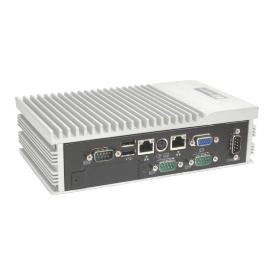
Series User’s Manual I/O Outlets The following figures show you I/O outlets on front view of the eBOX620-831-FL-CAN. Front View Front View drawing POWER-ON 12V DC-IN AUDIO Power & HDD POWER CONNECTORS Active INPUT Indicators CONNECTOR Introduction... - Page 21 Series User’s Manual Rear View Rear View drawing 2 x USB 2.0 RJ-45 CONNECTORS PS/2 VGA CONNECTOR CONNECTORS FOR Ethernet CONNECTORS Front Access CF slot COM1/2/3 CANBUS cover CONNECTORS CONNECTOR Introduction...
-
Page 22: Packing List
Series User’s Manual Packing List The package bundled with your eBOX620-831-FL-CAN should contain the following items: eBOX620-831-FL-CAN System Unit x 1 eBOX620-831-FL-CAN Quick Manual x 1 CD x 1 (For Driver and User’s Manual) Keyboard/Mouse Y-cable Screws pack x1... - Page 23 Series User’s Manual MEMO Introduction...
-
Page 24: Chapter 2
Series User’s Manual CHAPTER 2 HARDWARE INSTALLATION The eBOX620-831-FL-CAN is convenient for your various hardware configurations, such as Memory Module, HDD (Hard Disk Drive), and CompactFlash card. The chapter 2 will show you how to install the hardware. -
Page 25: Installing The Memory Module
Series User’s Manual Installing the Memory Module Step 1 Turn off the system, and unplug the power cord. Step 2 Turn the system upside down to locate screws at the bottom, loosen screws. - Page 26 Series User’s Manual Step 3 Remove the bottom cover. Step 4 Loosen screws of HDD bracket...
- Page 27 Series User’s Manual Step 5 Remove the HDD bracket Step 6 Locate the memory module, insert the gold colored contact into the socket.
- Page 28 Series User’s Manual Step 7 Push the module down, until it is firmly seated by locking two latches on the sides. Step 8 Close the cover to the chassis, and fasten all screws.
-
Page 29: Installing The Sata Hdd
Series User’s Manual Installing the SATA HDD Step 1 Turn off the system, and unplug the power cord. Step 2 Turn the system upside down to locate screws at the bottom, loosen screws. - Page 30 Series User’s Manual Step 3 Remove the bottom cover. Step 4 Loosen screws of HDD bracket...
- Page 31 Series User’s Manual Step 5 Remove the HDD bracket Step 6 Assembly the HDD bracket together with the SATA...
- Page 32 Series User’s Manual Step 7 Connect SATA cable and power cable to SATA HDD.
- Page 33 Series User’s Manual Step 8 Close the HDD bracket to the chassis, and fasten all screws. Step 9 Close the bottom cover to the chassis, and fasten all screws.
-
Page 34: Installing The Compactflash
Series User’s Manual Installing the CompactFlash Step 1 Turn off the system, and unplug the AC/DC power cord. Step 2 Turn the system rotate to CF cover side and locate screws at the front and bottom side. Step 3 Loosen screws to remove the CF cover. - Page 35 Series User’s Manual Step 3 Stick the Mylar onto the Compact Flash card CF card connector Mylar fin for hand hold Step 4 Slide CF card into CF slot with caution. Step 5 Close the cover to the chassis, and fasten all screws.
-
Page 36: Installing The Wall Mount
Series User’s Manual Installing the Wall Mount The eBOX620-831-FL-CAN provides Wall Mount that customers can install as below: Step 1 Prepare Wall Mount assembling components (screws and bracket) ready. - Page 37 Series User’s Manual Step 2 Loose the screw of four footpads at the bottom of eBOX620-831-FL-CAN and remove footpad.
- Page 38 Series User’s Manual Step 3 Fix the wall mount to the correct location, and fasten all screws.
-
Page 39: Installing The Vesa Mount (Optional)
Series User’s Manual Installing the VESA Mount (optional) The eBOX620-831-FL-CAN provides VESA Mount that customers can install as below: Step 1 Prepare VESA Mount assembling components (screws and VESA mount bracket) ready. - Page 40 Series User’s Manual Step 2 Loose the screw of four footpads at the bottom of eBOX620-831-FL-CAN, and remove footpad.
- Page 41 Series User’s Manual Step 3 Decide correct mounting direction. eBOX620-831-FL- CAN supports both 100x100mm and 75x75mm VESA mount. The 100x100mm type has special direction. 100x100mm 75x75mm...
- Page 42 Series User’s Manual Step 4 Fix the VESA mount to the correct location, and fasten all screws.
-
Page 43: Installing The Din-Rail Mount (Optional)
Series User’s Manual Installing the Din-Rail Mount (optional) The eBOX620-831-FL-CAN provides Din-Rail Mount that customers can install as below: Step 1 Prepare Din-Rail Mount assembling components (screws, Din-rail and VESA mount bracket) ready. - Page 44 Series User’s Manual Step 2 Loose the screw of four footpads at the bottom of eBOX620-831-FL-CAN, and remove footpad. Step 3 Fix the VESA mount to the correct location, and fasten all screws.
- Page 45 Series User’s Manual Step 4 Fix the Din-rail mount bracket to the correct location, and fasten all screws.
- Page 46 Series User’s Manual MEMO...
-
Page 47: Chapter 3
Series User’s Manual CHAPTER 3 Jumper Setting & Connector Proper jumper settings configure the eBOX620-831-FL-CAN to meet your application purpose. We are herewith listing a summary table of all jumpers and default settings for onboard devices, respectively. SBC layout... - Page 48 Series User’s Manual Solder Side NOTE: We strongly recommended that you should not modify any unmentioned jumper setting without AXIOMTEK FAE’s instruction. Any modification without instruction might cause system to become damage.
-
Page 49: Jumper Setting Summary
Series User’s Manual Jumper Setting Summary Proper jumper settings configure the eBOX620-831-FL-CAN to meet your application purpose. We are herewith listing a summary table of all jumpers and default settings for onboard devices, respectively. Jumper Default Setting Jumper Setting... -
Page 50: Audio Output Jumper (Jp2)
Series User’s Manual 3.2.1 Audio Output Jumper (JP2) This jumper is to select the Audio output. Description Function Jumper Setting Line Out (Default) Audio Output Speaker Out ™ 3.2.2 CompactFlash Voltage Jumper (JP4) ™ The jumper is to select the voltage for CompactFlash interface. -
Page 51: Cmos Clear Jumper (Jp5)
Series User’s Manual 3.2.3 CMOS Clear Jumper (JP5) You may need to use this jumper is to clear the CMOS memory if incorrect settings in the Setup Utility. Description Function Jumper Setting Normal (Default) CMOS Clear Clear CMOS... -
Page 52: Connectors
Connectors connect the board with other parts of the system. Loose or improper connection might cause problems. Make sure all connectors are properly and firmly connected. Here is a summary table shows you all connectors on the eBOX620-831-FL-CAN Series. External Connectors Section DC-in Jack Power Connector 3.3.1... -
Page 53: Dc-In Jack Power Connector
Series User’s Manual 3.3.1 DC-in Jack Power Connector Connect it to the power AC-DC 60W Adapter Signal +12V 3.3.2 Serial Port Connector The system has three serial ports. COM1~COM3 are RS-232 ports. Description DCD, Data Carrier Detect RXD, Receive Data... -
Page 54: Vga Connector
Series User’s Manual Description DCD, Data Carrier Detect COM3 RXD, Receive Data TXD, Transmit Data DTR, Data Terminal Ready GND, Ground DSR, Data Set Ready RTS, Request To Send CTS, Clear To Send RI, Ring Indicator 3.3.3 VGA Connector The VGA connector is a slim type 15-pin D-Sub connector which is common for the CRT VGA display. -
Page 55: Lan Connector (Lan1, Lan2)
Series User’s Manual 3.3.4 LAN Connector (LAN1, LAN2) The RJ-45 connector is for Ethernet. To connect the board to a 1000/100/10 Base-T hub, just plug one end of the cable into connector and connect the other end (phone jack) to a... -
Page 56: Atx Power On/Off Button
Series User’s Manual 3.3.6 ATX Power On/OFF Button The ATX power button is on the I/O side. It can allow users to control eBOX620-801-FL power on/off. Signal PSIN 3.3.7 Audio Connector These two audio jacks ideal are for Audio Mic-In and Audio Line- out. -
Page 57: Canbus Connector
Series User’s Manual 3.3.9 CANBUS Connector The system supports a CANBUS interface, the connector is a 9-pin D-sub connector. It supports CAN 2.0A and 2.0B standard. Description CANBUS CAN_L CAN_GND CAN_GND CAN_H 3.3.10 SATA Connector The SATA connector is for high-speed SATA interface ports and they can be connected to hard disk devices. -
Page 58: Sata Power Connector
Series User’s Manual 3.3.11 SATA Power Connector Signal +5 VDC +5 VDC +5 VDC +12 VDC +12 VDC +12 VDC... -
Page 59: Compactflash™ Socket
Series User’s Manual 3.3.12 CompactFlash™ Socket The system is equipped with a CompactFlash type-II socket with DMA mode to support an IDE interface CompactFlash disk. The socket is designed to avoid incorrect installation of the CompactFlash disk card. When installing or removing the... -
Page 60: Ddr2 Sodimm Socket
Series User’s Manual Address 2 DMAREQ Address 1 DMAACK- Address 0 DASP# Data 0 PDIAG# Data 1 Data 8 Data 2 Data 9 IOCS16# Data 10 CD2# 3.3.13 DDR2 SODIMM Socket eBOX620-831-FL-CAN supports standard DDR2 200-pin 400/533 MHz SO-DIMM pin define. -
Page 61: Chapter 4
Series User’s Manual CHAPTER 4 AMI BIOS SETUP UTILITY This chapter provides users with detailed description how to set up basic system configuration through the AMIBIOS8 BIOS setup utility. Starting To enter the setup screens, follow the steps below: Turn on the computer and press the <Del>... -
Page 62: Navigation Keys
Series User’s Manual Navigation Keys The BIOS setup/utility uses a key-based navigation system called hot keys. Most of the BIOS setup utility hot keys can be used at any time during the setup navigation process. These keys include <F1>, <F10>, <Enter>, <ESC>, <Arrow> keys, and so on. -
Page 63: Main Menu
Series User’s Manual Main Menu When you first enter the Setup Utility, you will enter the Main setup screen. You can always return to the Main setup screen by selecting the Main tab. There are two Main Setup options. They are described in this section. -
Page 64: Advanced Menu
Series User’s Manual Advanced Menu The Advanced menu allows users to set configuration of the CPU and other system devices. You can select any of the items in the left frame of the screen to go to the sub menus:... - Page 65 Series User’s Manual Configure advanced CPU settings This screen shows the CPU Configuration, and you can change the value of the selected option. Max CPUID Value Limit You can enable this item to let legacy operating systems boot even without support for CPUs with extended CPU ID functions.
- Page 66 Series User’s Manual Intel (R) C-STATE tech Use this item to enable or disable the C-State technology. Enhanced C-States This item allows you to enable or disable any available enhanced C-states ( C1E, C2E, C3E, C4E and Hard C4E).
- Page 67 Series User’s Manual Legacy IDE Channels When the ATA/IDE Configuration is set to Compatible, this item will be displayed. Primary/Secondary IDE Master Select one of the hard disk drives to configure IDE devices installed in the system by pressing <Enter> for more options.
- Page 68 Series User’s Manual Serial Port1 IRQ This item specifies the IRQ used by the serial port 1. Serial Port2 Address This item specifies the base I/O port address and Interrupt Request address of serial port 2. The Optimal setting is 2F8/IRQ3.
- Page 69 Series User’s Manual Hardware Health Configuration This screen shows the Hardware Health Configuration, and a description of the selected item appears on the right side of the screen. System Temperature/CPU Temperature These items display the temperature of CPU and System, Vcore,...
- Page 70 Series User’s Manual ACPI Settings You can use this screen to select options for the ACPI Settings, and change the value of the selected option. A description of the selected item appears on the right side of the screen.
- Page 71 Series User’s Manual General ACPI Configuration Scroll to this item and press <Enter> to view the General ACPI Configuration sub menu, which contains General ACPI (Advanced Configuration and Power Management Interface) options for your configuration.
- Page 72 Series User’s Manual Advanced ACPI Configuration Scroll to this item and press <Enter> to view the Advanced ACPI Configuration sub menu, which contains Advanced ACPI (Advanced Configuration and Power Management Interface) options for your configuration.
- Page 73 Series User’s Manual South Bridge ACPI Configuration Scroll to this item and press <Enter> to view the Chipset ACPI Configuration sub menu, which contains Chipset ACPI (Advanced Configuration and Power Management Interface) options for your configuration.
- Page 74 Series User’s Manual APM Configuration You can use this screen to select options for the APM Configuration, and change the value of the selected option. A description of the selected item appears on the right side of the screen.
- Page 75 Series User’s Manual This setting prevents the BIOS from initiating any power Disabled saving modes concerned with the video display or monitor. This option places the monitor into suspend mode after the specified period of display inactivity has expired. This means the monitor is not off.
- Page 76 Series User’s Manual running the power saving states. Power Button Mode This option specifies how the externally mounted power button on the front of the computer chassis is used. The default setting is On/Off. Pushing the power button turns the computer on or off.
- Page 77 Series User’s Manual MPS Configuration This screen shows the MPS (Multi Processor Specification) Configuration, and you can change its value. A description of the selected item appears on the right side of the screen. MPS Revision Use this item to select MPS (Multi Processor Specification)
- Page 78 Series User’s Manual PCI Express Configuration This screen shows the PCI Express Configuration, and you can change its value. A description of the selected item appears on the right side of the screen. Active State Power-Management Use this item to enable or disable the function of Active State Power-Management to provide you with lower power consumption.
- Page 79 Series User’s Manual USB Configuration You can use this screen to select options for the USB Configuration, and change the value of the selected option. A description of the selected item appears on the right side of the screen.
-
Page 80: Pci Pnp Menu
Series User’s Manual PCI PnP Menu The PCI PnP menu allows users to change the advanced settings for PCI/PnP devices. Clear NVRAM Use this item to clear the data in the NVRAM (CMOS). Here are the options for your selection, No and Yes. - Page 81 Series User’s Manual selection. Palette Snooping Some old graphic controllers need to “snoop” on the VGA palette, and then map it to their display as a way to provide boot information and VGA compatibility. This item allows such snooping to take place. Here are the options for your selection, Disabled and Enabled.
-
Page 82: Boot Menu
Series User’s Manual Boot Menu The Boot menu allows users to change boot options of the system. You can select any of the items in the left frame of the screen to go to the sub menus: Boot Settings Configuration... - Page 83 Series User’s Manual Boot Settings Configuration Quick Boot Enabling this item lets the BIOS skip some power on self tests (POST). The default setting is Enabled. LAN1/LAN2 Boot Use these items to enable or disable the Boot ROM function of the onboard LAN chip when the system boots up.
- Page 84 Series User’s Manual The default setting is On. PS/2 Mouse Support This item determines if the BIOS should reserve IRQ12 for the PS/2 mouse or allow other devices to make use of this IRQ. Here are the options for your selection, Auto, Enabled and Disabled.
- Page 85 Series User’s Manual Removable Drives Use this screen to view the removable drives in the system. The BIOS will attempt to arrange the removable drive boot sequence automatically. You can also change the booting sequence.
-
Page 86: Security Menu
Series User’s Manual Security Menu The Security menu allows users to change the security settings for the system. Change Supervisor Password Select this option and press <Enter> to access the sub menu. You can use the sub menu to change the supervisor password. - Page 87 Series User’s Manual Set this item to prevent the Boot Sector Virus Protection. Disabled This is the default setting. Select Enabled to enable boot sector protection. It displays a warning when any program (or virus) issues a Disk Format command or attempts to write to the boot sector of the hard disk drive.
-
Page 88: Chipset Menu
Series User’s Manual Chipset Menu The Chipset menu allows users to change the advanced chipset settings. You can select any of the items in the left frame of the screen to go to the sub menus: North Bridge Configuration South Bridge Configuration For items marked with “... - Page 89 Series User’s Manual North Bridge Configuration DRAM Frequency This item allows you to control the Memory Clock. Configure DRAM Timing by SPD This item can enable or disable DRAM timing by SPD (Serial Presence Detect) device, which is a small EEPROM chip on the memory module, containing important information about the module speed, size, addressing mode and various parameters.
- Page 90 Series User’s Manual Internal Graphics Mode Select This item allows you to select the amount of system memory used by the internal graphics device. Video Function Configuration Press <Enter> for the sub-menu for setting up video function.
- Page 91 Series User’s Manual South Bridge Configuration USB Function This item allows you to enable or disable USB function. USB 2.0 Controller This item allows you to enable or disable the USB 2.0 controller. Audio Controller This item allows you to enable or disable the audio support.
-
Page 92: Exit Menu
Series User’s Manual Exit Menu The Exit menu allows users to load your system configuration with optimal or failsafe default values. Save Changes and Exit When you have completed the system configuration changes, select this option to leave Setup and reboot the computer so the new system configuration parameters can take effect. - Page 93 Series User’s Manual Load Optimal Defaults It automatically sets all Setup options to a complete set of default settings when you select this option. The Optimal settings are designed for maximum system performance, but may not work best for all computer applications. In particular, do not use the Optimal Setup options if your computer is experiencing system configuration problems.
-
Page 94: Watchdog Timer
Series User’s Manual APPENDIX A WATCHDOG TIMER What is Watchdog Timer The integrated Watchdog Timer can be set up by programming. There are 1~255 levels available. As long as the vaule of timer is set, after enabling, the countdown of the value is starting. -
Page 95: How To Use The Watchdog Timer
Series User’s Manual How to Use the Watchdog Timer Start ↓ ↓ ↓ ↓ Un-Lock WDT: O 2E 87 ; Un-lock super I/O O 2E 87 ; Un-lock super I/O ↓ ↓ ↓ ↓ Select Logic device: O 2E 07 O 2F 08 ↓... -
Page 96: Program Sample
Series User’s Manual Program Sample O 2E 87 O 2E 87 O 2E 07 O 2F 08 Logical Device 8 O 2E 30 Activate O 2F 01 O 2E F5 O 2F N Set Minute or Second : N=08 (Min),00(Sec) -
Page 97: Canbus Introduction
Series User’s Manual APPENDIX B CANBUS Introduction CANBUS Module Layout... -
Page 98: Connection For Can Transmission
Series User’s Manual Block Diagram Pin Define Please refre to “3.3.9 CANBUS Connector” Connection for CAN transmission...
Need help?
Do you have a question about the eBOX620-831-FL-CAN Series and is the answer not in the manual?
Questions and answers