Table of Contents
Advertisement
Quick Links
Advertisement
Table of Contents

Related Manuals for AXIOMTEK eBOX623-831-FL Series


Summary of Contents for AXIOMTEK eBOX623-831-FL Series
- Page 1 Series Embedded System User’s Manual...
-
Page 2: Disclaimers
Axiomtek does not make any commitment to update the information in this manual. Axiomtek reserves the right to change or revise this document and/or product at any time without notice No part of this document may be reproduced, stored in a retrieval system, or transmitted, in any form or by any means, electronic, mechanical, photocopying, recording, or otherwise, without the prior written permission of Axiomtek Co., Ltd. -
Page 3: Safety Precautions
Safety Precautions Before getting started, please read the following important safety precautions. The eBOX623-831-FL does not come equipped with an operating system. An operating system must be loaded first before installing any software into the computer. Be sure to ground yourself to prevent static charge when installing the internal components. -
Page 4: Classification
Classification Degree of production against electric shock : not classified Degree of protection against the ingress of water : IP40 Equipment not suitable for use in the presence of a flammable anesthetic mixture with air or with oxygen or nitrous oxide. Mode of operation : Continuous... -
Page 5: General Cleaning Tips
General Cleaning Tips You may need the following precautions before you begin to clean the computer. When you clean any single part or component for the computer, please read and understand the details below fully. When you need to clean the device, please rub it with a piece of dry cloth. Be cautious of the tiny removable components when you use a vacuum cleaner to absorb the dirt on the floor. -
Page 6: Scrap Computer Recycling
If the computer equipment’s need the maintenance or are beyond repair, we strongly recommended that you should inform your Axiomtek distributor as soon as possible for the suitable solution. For the computers that are no longer useful or no longer working well, please contact your Axiomtek distributor for recycling and we will make the proper arrangement. -
Page 7: Table Of Contents
Table of Contents Disclaimers ......................ii Safety Precautions ....................iii Classification ......................iv General Cleaning Tips .................... v Scrap Computer Recycling ..................vi CHAPTER 1 INTRODUCTION ................ 1 General Description ................2 System Specifications ................ 3 1.2.1 CPU ........................3 1.2.2 I/O System ...................... - Page 8 3.3.8 ATX Power On/OFF Button ................44 3.3.9 Audio Connector ..................... 44 3.3.10 SATA Connector ..................... 45 3.3.11 SATA Power Connector.................. 45 3.3.12 CFast™ Socket ....................46 3.3.13 DDR3 SODIMM Socket ................... 46 3.3.14 Express Mini Card Slot ................... 47 CHAPTER 4 AMI BIOS SETUP UTILITY ............
-
Page 9: Chapter 1 Introduction
Series User’s Manual CHAPTER 1 INTRODUCTION This chapter contains general information and detailed specifications of the eBOX623-831-FL. The Chapter 1 includes the following sections: General Description System Specification Dimensions I/O Outlets Packing List Introduction... -
Page 10: General Description
Series User’s Manual General Description The eBOX623-831-FL is an embedded system that supports onboard dual core Intel® Atom™ processor D2550 (1.86 GHz) or N2600 (1.6GHz) processor to provide W indows 7, W indows 7 Embedded or Linux, suitable for the most endurable operation. -
Page 11: System Specifications
Series User’s Manual System Specifications 1.2.1 CPU ® Intel Atom dual core D2550 1.86 GHz. ® Intel Atom dual core N2600 1.6 GHz Chipset Intel® NM10 chipset BIOS American Megatrends Inc. UEFI (Unified Extensible Firmware Interface) BIOS. -
Page 12: Driver Cd Content
Series User’s Manual Weight 1.98 kg (4.36 lb) without package 2.6 kg (17.64 lb) with package Dimensions 200mm(7.87”) (W) x 120mm(4.72”) (D) x 55.8mm(2.2”) (H) 1.2.4 Driver CD Content Driver Audio ... -
Page 13: Dimensions
Series User’s Manual Dimensions The following diagrams show you dimensions and outlines of the eBOX623-831-FL. 1.3.1 System Dimension Introduction... - Page 14 Series User’s Manual Introduction...
-
Page 15: Wall Mount Bracket Dimension
Series User’s Manual 1.3.2 Wall mount Bracket Dimension Introduction... -
Page 16: Vesa Mount Bracket Dimension
Series User’s Manual 1.3.3 VESA Mount Bracket Dimension Introduction... -
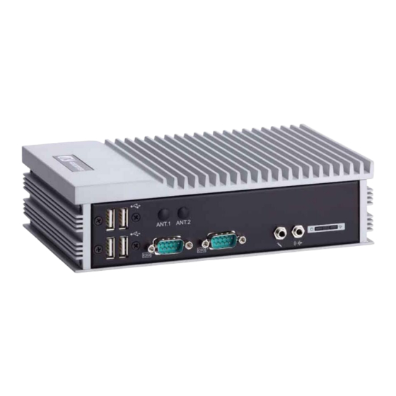
Page 17: I/O Outlets
Series User’s Manual I/O Outlets The following figures show you I/O outlets on front view of the eBOX623-831-FL. Front View Front View drawing SMA type Antenna hole 4 x USB 2.0 COM1/2 Audio connectors Power & HDD... - Page 18 Series User’s Manual Rear View Rear View drawing Display Port 2 x USB 2.0 RJ-45 LAN connectors connectors connectors connectors 12V DC-IN power COM3/4 input connector Front Access POWER Connectors CFast slot cover Switch Introduction...
-
Page 19: Packing List
Series User’s Manual Packing List The package bundled with your eBOX623-831-FL should contain the following items: eBOX623-831-FL System Unit x 1 eBOX623-831-FL Quick Manual x 1 CD x 1 (For Driver and User’s Manual) Screws pack x1 ... -
Page 20: Model List
1.6GHz dual core processor, US power cord Fanless embedded system with Intel® ATOM® N2600 eBOX623-831-FL-N2600-1.6G-EU 1.6GHz dual core processor, EU power cord If you cannot find this package or any items are missing, please contact Axiomtek distributors immediately. Introduction... -
Page 21: Chapter 2 Hardware Installation
Series User’s Manual CHAPTER 2 HARDWARE INSTALLATION The eBOX623-831-FL is convenient for your various hardware configurations, such as Memory Module, HDD (Hard Disk Drive), SSD (Solid State Drive) and CFast card. The chapter 2 will show you how to install the hardware. - Page 22 Series User’s Manual Step 4 Remove the HDD bracket Step 5 Take out the thermal pad from accessory kit Hardware Installation...
- Page 23 Series User’s Manual Step 6 Remove the transparent plastic Mylar from thermal pad, and stick the thermal pad onto motherboard. Step 7 Locate the memory module, insert the gold colored contact into the socket. Hardware Installation...
- Page 24 Series User’s Manual Step 8 Push the module down, until it is firmly seated by locking two latches on the sides. Step 9 Take 2 thermal pad, remove the transparent plastic mylar and stick it onto memory. Hardware Installation...
- Page 25 Series User’s Manual Step 10 Fasten screws of HDD bracket Step 11 Close the cover to the chassis, and fasten all screws. Hardware Installation...
-
Page 26: Installing The Sata Hdd
Series User’s Manual Installing the SATA HDD Step 1 Turn off the system, and unplug the power cord. Step 2 Turn the system upside down to locate screws at the Bottom, loosen screws. Step 3 Remove the bottom cover and Loosen screws of HDD bracket... - Page 27 Series User’s Manual Step 5 Remove the HDD bracket Step 6 Assembly the HDD bracket together with the SATA HDD Hardware Installation...
- Page 28 Series User’s Manual Step 7 Connect SATA cable and power cable to SATA HDD. Hardware Installation...
- Page 29 Series User’s Manual Step 8 Fasten screws of HDD bracket Step 9 Close the cover to the chassis, and fasten all screws. Hardware Installation...
-
Page 30: Installing The Cfast
Series User’s Manual Installing the CFast™ Step 1 Turn off the system, and unplug the power cord. Step 2 Turn the system upside down to locate screws at the Bottom, loosen screws. Step 3 Loosen screws to remove the CFast cover. - Page 31 Series User’s Manual Step 5 Slide CFast card into CFast slot with caution. Step 6 Bend the CFast Mylar with caution. Step 7 Close the cover to the chassis, and fasten all screws. Hardware Installation...
-
Page 32: Installing The Express Mini Card
Series User’s Manual Installing the Express Mini Card Step 1 Turn off the system, and unplug the power cord. Step 2 Turn the system upside down to locate screws at the Bottom, loosen screws. Step 3 Loosen screws at left side and right side. There are Total 8 screws. - Page 33 Series User’s Manual Step 4 Remove the top heat sink to locate the Express Mini Card slot. Step 5 Slide Mini card into Mini Card slot with caution and Fasten screw of Express Mini Card. Step 6 Assembly the Top Cover back and fasten all screws.
-
Page 34: Installing The Wall Mount (Optional)
Series User’s Manual Installing the Wall Mount (Optional) The eBOX623-831-FL provides Wall Mount that customers can install as below: Step 1 Prepare Wall Mount assembling components (screws and Bracket) ready. Hardware Installation... - Page 35 Series User’s Manual Step 2 Loose the screw of four footpads at the bottom of eBOX623-831-FL and remove footpad. Hardware Installation...
- Page 36 Series User’s Manual Step 3 Fix the wall mount to the correct location, and fasten all screws. Hardware Installation...
-
Page 37: Installing The Vesa Mount (Optional)
Series User’s Manual Installing the VESA Mount (optional) The eBOX623-831-FL provides VESA Mount that customers can install as below: Step 1 Prepare VESA Mount assembling components (screws and VESA mount bracket) ready. Step 2 Loose the screw of four footpads at the bottom of eBOX623-831-FL, and emove footpad. - Page 38 Series User’s Manual Step 3 Decide correct mounting direction.eBOX623-831-FL supports both 100x100mm and 75x75mm VESA mount. The 100x100mm type has special direction. 100x100mm 75x75mm Hardware Installation...
- Page 39 Series User’s Manual Step 4 Fix the VESA mount to the correct location, and fasten all screws. Hardware Installation...
-
Page 40: Installing The Din-Rail Mount (Optional)
Series User’s Manual Installing the Din-Rail Mount (optional) The eBOX623-831-FL provides Din-Rail Mount that customers can install as below: Step 1 Prepare Din-Rail Mount assembling components (screws, Din-rail and VESA mount bracket) ready. Hardware Installation... - Page 41 Series User’s Manual Step 2 Loose the screw of four footpads at the bottom of eBOX623-831-FL and remove footpad. Step 3 Fix the VESA mount to the correct location, and fasten all screws. Hardware Installation...
- Page 42 Series User’s Manual Step 4 Fix the Din-rail mount bracket to the correct location, and fasten all screws. Hardware Installation...
-
Page 43: Chapter 3 Jumper Setting & Connector
Series User’s Manual CHAPTER 3 Jumper Setting & Connector Proper jumper settings configure the eBOX623-831-FL to meet your application purpose. We are herewith listing a summary table of all jumpers and default settings for onboard devices, respectively. SBC layout TOP Side Jumper Setting &... - Page 44 Series User’s Manual Bottom Side NOTE: We strongly recommended that you should not modify any unmentioned jumper setting without Axiomtek FAE’s instruction. Any modification without instruction might cause system to become damage. Jumper Setting & Connector...
-
Page 45: Jumper Settings
Series User’s Manual Jumper Settings Jumper is a small component consisting of jumper clip and jumper pins. Install jumper clip on 2 jumper pins to close. And remove jumper clip from 2 jumper pins to open. Below illustration shows how to set up jumper. -
Page 46: Auto Power On
Series User’s Manual 3.2.1 Auto Power On If JP1 is enabled for AC power input, the system will be automatically power on without pressing soft power button. If JP1 is disabled for AC power input, it is necessary to manually press soft power button to power on the system. -
Page 47: Com1 Rs-232/422/485 Mode Setting
Series User’s Manual 3.2.3 COM1 RS-232/422/485 Mode Setting Use jumpers of JP8, JP9 and JP10 to set COM1 port to operate as RS-232, RS-422 or RS- 485 communication mode. Function Setting JP8 1-2 close RS-232 mode JP9 3-5, 4-6 close... -
Page 48: Connectors
Series User’s Manual Connectors Connectors connect the system with other parts/devices. Loose or improper connection might cause problems. Make sure all connectors ar e properly and firmly connected. Below summary table shows you all connectors on the eBOX623-831-FL. External Connectors... -
Page 49: Ac-Dc Jack Power In Connector
Series User’s Manual 3.3.1 AC-DC Jack Power In Connector The system supports a DC12V DC-in Jack connector for system power input. Connect it to the power AC-DC 60W Adapter Signal +12V 3.3.2 COM1~COM2 Serial Port Connector The system has four serial ports. COM1~COM2 are RS-232/422/485 ports. Please refer to Chapter 3.2.2 and 3.2.3 for the setting. -
Page 50: Com3~Com4 Serial Port Connector
Series User’s Manual 3.3.3 COM3~COM4 Serial Port Connector The system has four serial ports. COM3~COM4 are RS-232 ports. Description DCD, Data Carrier Detect RXD, Receive Data COM3 TXD, Transmit Data DTR, Data Terminal Ready GND, Ground DSR, Data Set Ready... -
Page 51: Displayport Connector
Series User’s Manual 3.3.5 DisplayPort Connector DisplayPort interface is also called DP port. Signal DPB_LANE0 DPB_LANE0# DPB_LANE1 DPB_LANE1# DPB_LANE2 DPB_LANE2# DPB_LANE3 DPB_LANE3# Detect Pin DPB_AUX DPB_AUX# DPB_HPDE +3.3V 3.3.6 LAN Connector (LAN1, LAN2) The RJ-45 connector is for Ethernet. To connect the board to a 1000/100/10 Base-T... -
Page 52: Usb Connector
Series User’s Manual 3.3.7 USB Connector The Universal Serial Bus connectors are compliant with USB 2.0 (480Mbps), and ideally for installing USB peripherals such as keyboard, mouse, scanner, etc. Signal USB Port 0 Signal USB Port 1 USB VCC... -
Page 53: Sata Connector
Series User’s Manual 3.3.10 SATA Connector The SATA connector is for high-speed SATA interface ports and they can be connected to hard disk devices. Signal SATA_TX+ SATA_TX- SATA_RX- SATA_RX+ 3.3.11 SATA Power Connector The SATA connector is for high-speed SATA interface ports and they can be connected to hard disk devices. -
Page 54: Cfast™ Socket
Series User’s Manual 3.3.12 CFast™ Socket The system is equipped with a CFast™ socket on the bottom side to support a CFast™ card which is based on the Serial ATA bus . The socket is specially designed to avoid incorrect installation of the CFast™ card. W hen installing or removing the CFast™... -
Page 55: Express Mini Card Slot
Series User’s Manual 3.3.14 Express Mini Card Slot PCI Express Mini Card connector supports a PCI Express x1 link and a USB 2.0 link. A PCI Express Mini Card can be applied to either PCI Express or USB 2.0. It complies with PCI-Express Mini Card Spec. - Page 56 Series User’s Manual This page is intentionally left blank. Jumper Setting & Connector...
-
Page 57: Chapter 4 Ami Bios Setup Utility
Series User’s Manual CHAPTER 4 AMI BIOS SETUP UTILITY This chapter provides users with detailed description how to set up basic system configuration through the AMI BIOS setup utility. Starting To enter the setup screens, follow the steps below: Turn on the computer and press the <Del>... -
Page 58: Main Menu
Series User’s Manual Main Menu When you first enter the setup utility, you will enter the Main setup screen. You can always return to the Main setup screen by selecting the Main tab. System Time/Date can be set up as described below. -
Page 59: Advanced Menu
Series User’s Manual Advanced Menu Launch PXE OpROM Use this item to enable or disable the boot ROM function of the onboard LAN chip when the system boots up. Launch Storage OpROM Enable or disable boot option for legacy mass storage devices with option ROM. - Page 60 Series User’s Manual ACPI Settings ACPI Sleep State When the sleep button is pressed, the system will be in the ACPI sleep state. The default is S1 (CPU Stop Clock). AMI BIOS Setup Utility...
- Page 61 Series User’s Manual Trusted Computing This screen provides function for specifying the TPM settings. TPM Support Enable or disable BIOS support for security device. “Disable” is the default. Current Status Information Display current TPM status information.
- Page 62 Series User’s Manual CPU Configuration This screen shows the CPU Configuration. AMI BIOS Setup Utility...
- Page 63 Series User’s Manual IDE Configuration In the IDE Configuration menu, you can see the currently installed hardware in the SATA ports. During system boot up, the BIOS automatically detects the presence of SATA devices. Configure SATA as Determine how SATA controller(s) operate.
- Page 64 Series User’s Manual NCT6627UD Super IO Configuration You can use this screen to select options for the Super IO Configuration, and change the value of the selected option. A description of the selected item appears on the right side of the screen.
- Page 65 Series User’s Manual NCT6627UD HW Monitor This screen monitors hardware health status. This screen displays the temperature of system and CPU, cooling fan speed in RPM and system voltages (VCORE, +1.05V, +3.3V and +12V). AMI BIOS Setup Utility...
-
Page 66: Chipset Menu
Series User’s Manual Chipset Menu The Chipset menu allows users to change the advanced chipset settings. You can select any of the items in the left frame of the screen to go to the sub menus: ► Host Bridge For items marked with “”, please press <Enter>... - Page 67 Series User’s Manual Host Bridge This screen allows users to configure parameters of Host Bridge chipset. Memory Frequency and Timing Use this item to refer to the information related to memory frequency. Intel IGD Configuration Use this item to configure internal graphics controller.
- Page 68 Series User’s Manual Intel IGD Configuration This screen shows the configure parameters of internal graphics controller. IGFX – Boot Type Select the video device which will be activated during POST (Power-On Self Test). This has no effect if external graphics present.
-
Page 69: Boot Menu
Series User’s Manual Boot Menu The Boot menu allows users to change boot options of the system. Setup Prompt Timeout Number of seconds to wait for setup activation key. 65535(0xFFFF) means indefinite waiting. Bootup NumLock State Use this item to select the power-on state for the NumLock. -
Page 70: Security Menu
Series User’s Manual Security Menu The Security menu allows users to change the security settings for the system. Administrator Password This item indicates whether an administrator password has been set (installed or uninstalled). User Password This item indicates whether an user password has been set (installed or uninstalled). -
Page 71: Save & Exit Menu
Series User’s Manual Save & Exit Menu The Save & Exit menu allows users to load your system configuration with optimal or fail-safe default values. Save Changes and Exit When you have completed the system configuration changes, select this option to leave Setup and return to Main Menu. - Page 72 Series User’s Manual Discard Changes Select this option to quit Setup without making any permanent changes to the system configuration. Select Discard Changes from the Save & Exit menu and press <Enter>. Select Yes to discard changes. ...
-
Page 73: Chapter 5 Drivers Installation
Series User’s Manual CHAPTER 5 Drivers Installation The device drivers are located on the product information CD that comes with the eBOX623- 831-FL Series package. The auto-run function of drivers will guide you to install the utilities and device drivers under Windows system. You can follow the onscreen instructions to install these devices: ... - Page 74 Series User’s Manual 2. A Readme File Information screen appears to show you the system requirements and installation information. Click “Next” to next step. 3. Please wait while setup processes the following operations. AMI BIOS Setup Utility...
- Page 75 Series User’s Manual You are suggested to select “Yes, I want to restart this computer now”. Click “Finish” to complete the setup process and reboot. AMI BIOS Setup Utility...
-
Page 76: Installing Graphics Media Accelerator Driver
Series User’s Manual Installing Graphics Media Accelerator Driver 1. Run the setup.exe program from the driver directory in product information CD. Click “Next” to next step. AMI BIOS Setup Utility... - Page 77 Series User’s Manual ® License Agreement screen appears, please click “Yes” to next step. 2. When Intel 3. A Readme File Information screen appears to show you the system requirements and installation information. Click “Next” to next step. AMI BIOS Setup Utility...
- Page 78 Series User’s Manual 4. Please wait while setup processes the following operations. 5. When the following screen appears, please click “Next”. AMI BIOS Setup Utility...
- Page 79 Series User’s Manual 6. You are suggested to select “Yes, I want to restart this computer now”. Click “Finish” to complete the setup process and reboot. NOTE: After the computer reboots, the display is in extended mode. Please click hot key <Ctrl+Alt+F1>...
-
Page 80: Installing Ethernet Driver
Series User’s Manual Installing Ethernet Driver 1. Unzip PROWin32 for ethernet driver from the driver directory in product information CD. Click “Next” to start the installation. AMI BIOS Setup Utility... - Page 81 Series User’s Manual 2. When the following screen appears, please select the program features you want to install. Click “Next” to continue. 3. Click “Finish” to complete the installation. AMI BIOS Setup Utility...
-
Page 82: Installing Audio Driver
Series User’s Manual Installing Audio Driver 1. Run the setup.exe for audio from the driver directory in product information CD. Click “Next” to continue. AMI BIOS Setup Utility... - Page 83 Series User’s Manual You are suggested to select “Yes, I want to restart my computer now”. Click “Finish” to complete the setup process and reboot. AMI BIOS Setup Utility...
- Page 84 Series User’s Manual This page is intentionally left blank. AMI BIOS Setup Utility...
-
Page 85: Appendix A Watchdog Timer
Series User’s Manual Appendix A Watchdog Timer About Watchdog Timer Software stability is major issue in most application. Some embedded systems are not watched by human for 24 hours. It is usually too slow to wait for someone to reboot when computer hangs. - Page 86 Series User’s Manual Begin Begin Next Next Enable and Initialize Enable and Initialize Watchdog Timer Watchdog Timer Next Next Program “A” Program “A” Next Next Disable Watchdog Reset Watchdog Timer Timer Next Next Watchdog Timer...
-
Page 87: Sample Program
Series User’s Manual Sample Program Assembly sample code : ;Enable WDT: dx,2Eh al,87 ;Un-lock super I/O dx,al dx,al ;Select Logic device: dx,2Eh al,07h dx,al dx,2Fh al,08h dx,al ;Activate WDT: dx,2Eh al,30h dx,al dx,2Fh al,01h dx,al ;Set Second or Minute :... - Page 88 Series User’s Manual dx,al dx,2Fh al,Mh ;M=00h,01h,...FFh (hex),Value=0 to 255 dx,al ;(see below Note ;Disable WDT: dx,2Eh al,30h dx,al dx,2Fh al,00h ;Can be disabled at any time dx,al NOTE: If N=00h, the time base is set to second. M = time value...
- Page 89 Series User’s Manual If N=08h, the time base is set to minute. M = time value 00: Time-out Disable 01: Time-out occurs after 1 minute 02: Time-out occurs after 2 minutes 03: Time-out occurs after 3 minutes FFh: Time-out occurs after 255 minutes...
- Page 90 Series User’s Manual This page is intentionally left blank. Watchdog Timer...
Need help?
Do you have a question about the eBOX623-831-FL Series and is the answer not in the manual?
Questions and answers