
Related Manuals for GE Lullaby Warmer


Summary of Contents for GE Lullaby Warmer
- Page 1 GE Healthcare Lullaby™ Warmer Maintenance and Service manual Lullaby™ Warmer Mainte nance and Service Manual -English 2042376- 001 Rev G...
- Page 2 Contact your GE Representative for the most current information. Lullaby is a trademark owned by Datex-Ohmeda, Inc. GE and GE Monogram are trademarks of General Electric Company. All other company and product names mentioned may be trademarks of the companies with which they are associated.
- Page 3 ПРЕДУПРЕЖДЕНИЕ Това упътване за работа е налично само на английски език. (BG) Ако доставчикът на услугата на клиента изиска друг език, задължение на клиента е да осигури превод. Не използвайте оборудването, преди да сте се консултирали и разбрали упътването за работа. ...
- Page 4 UPOZORENJE Ovaj servisni priručnik dostupan je na engleskom jeziku. (HR) Ako davatelj usluge klijenta treba neki drugi jezik, klijent je dužan osigurati prijevod. Ne pokušavajte servisirati opremu ako niste u potpunosti pročitali i razumjeli ovaj servisni priručnik. Zanemarite li ovo upozorenje, može doći do ozljede davatelja usluge, operatera ili pacijenta uslijed strujnog udara, mehaničkih ili drugih rizika.
- Page 5 WARNING: This service manual is available in English only. (EN) If a customer’s service provider requires a language other than English, it is the customer’s responsibility to provide translation services. Do not attempt to service the equipment unless this service manual has been consulted and is understood.
- Page 6 Serviceanleitung gelesen und verstanden zu haben. Wird diese Warnung nicht beachtet, so kann es zu Verletzungen des Kundendiensttechnikers, des Bedieners oder des Patienten durch Stromschläge, mechanische oder sonstige Gefahren kommen. ΠΡΟΕΙΔΟΠΟΙΗΣΗ Το παρόν εγχειρίδιο σέρβις διατίθεται μόνο στα αγγλικά. (EL) ...
- Page 7 (IS) ensku, er það skylda viðskiptamanns að skaffa tungumálaþjónustu. Reynið ekki að afgreiða tækið nema að þessi þjónustuhandbók hefur verið skoðuð og skilin. Brot á sinna þessari aðvörun getur leitt til meiðsla á þjónustuveitanda, stjórnanda eða sjúklings frá raflosti, vélrænu eða öðrum áhættum. AVVERTENZA Il presente manuale di manutenzione è...
- Page 8 수리하려고 시도하지 마십시오. 본 경고 사항에 유의하지 않으면 전기 쇼크, 기계적 위험, 또는 기타 위험으로 인해 ¼비스 제공자, 사용자 또는 환자에게 부상을 입힐 수 있습니다. BRĪDINĀJUMS Šī apkopes rokasgrāmata ir pieejama tikai angļu valodā. (LV) Ja klienta apkopes sniedzējam nepieciešama informācija citā valodā, klienta pienākums ir nodrošināt tulkojumu.
- Page 9 usługi tłumaczenia jest obowiązkiem klienta. Nie próbować serwisować urządzenia bez zapoznania się z niniejszym podręcznikiem serwisowym i zrozumienia go. Niezastosowanie się do tego ostrzeżenia może doprowadzić do obrażeń serwisanta, operatora lub pacjenta w wyniku porażenia prądem elektrycznym, zagrożenia mechanicznego bądź innego. AVISO Este manual de assistência técnica encontra-se disponível unicamente em inglês.
- Page 10 ОСТОРОЖНО! Данное руководство по техническому обслуживанию представлено только на английском языке. (RU) Если сервисному персоналу клиента необходимо руководство не на английском, а на каком-то другом языке, клиенту следует самостоятельно обеспечить перевод. Перед техническим обслуживанием оборудования обязательно обратитесь к данному руководству и поймите изложенные в нем сведения.
- Page 11 manual. No se deberá dar servicio técnico al equipo, sin haber consultado y comprendido este manual de servicio. La no observancia del presente aviso puede dar lugar a que el proveedor de servicios, el operador o el paciente sufran lesiones provocadas por causas eléctricas, mecánicas o de otra naturaleza.
- Page 12 This page is left blank intentionally.
-
Page 13: Table Of Contents
Table of Contents IMPORTANT SAFETY INFORMATION ------------------------------------------------------- XXI WARNINGS, CAUTIONS AND NOTES ----------------------------------------------------------------- XXI SYMBOLS ------------------------------------------------------------------------------------- XXIII ABOUT THIS MANUAL ---------------------------------------------------------------------- XXVI SCOPE AND INTENDED USERS --------------------------------------------------------------------- XXVI ORGANIZATION OF THIS MANUAL ----------------------------------------------------------------- XXVI CHAPTER 1 INTRODUCTION ---------------------------------------------------------------- 1 INDICATIONS FOR USE (INTENDED USE) ---------------------------------------------------- 1 MECHANICAL CONTROLS AND CABLE CONNECTIONS ------------------------------------ 2 CONTROLS AND DISPLAYS ------------------------------------------------------------------- 4 CONTROL MODES AND INDICATION -------------------------------------------------------- 6... - Page 14 CONNECTING THE POWER CORD ---------------------------------------------------------- 49 MOUNTING THE ACCESSORIES ------------------------------------------------------------- 49 5.8.1 Mounting the IV pole -------------------------------------------------------------------- 50 5.8.2 Mounting the Monitor /Instrument Tray ----------------------------------------------- 51 5.8.3 Mounting the Utility Pole ---------------------------------------------------------------- 51 5.8.4 Mounting the Cylinder Holder and the Cylinder -------------------------------------- 52 5.8.5 Mounting the Drawer Assembly -------------------------------------------------------- 53 5.8.6...
- Page 15 7.1.16 Replacing the Front and Rear Covers of Height Skirt (Part of FRU Kit No. 2043952- 001) 7.1.17 Replacing the Castors (FRU Kit No. 2043945-001) and Leg Cap (Part of FRU Kit No. 2043952-001) ---------------------------------------------------------------------------------------- 91 7.1.18 Replacing the Mattress (FRU Kit No. 2045963-001), Clear Plexiglas Plate (FRU Kit No.
- Page 16 WARRANTY ----------------------------------------------------------------------------------- 138 GE SERVICE CENTERS ------------------------------------------------------------------------ 139 2042376-001 Rev G ©2012 General Electric Company. All rights reserved. Lullaby Warmer...
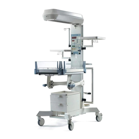
- Page 17 Table of Figures Figure 1: Lullaby Warmer ------------------------------------------------------------------ 1 Figure 2: Front Oblique View ----------------------------------------------------------------- 2 Figure 3: Front View -------------------------------------------------------------------------- 2 Figure 4: Side View --------------------------------------------------------------------------- 3 Figure 5: Back View --------------------------------------------------------------------------- 3 Figure 6: Controls and Displays ------------------------------------------------------------- 4 Figure 7: Temperature Settings and Modes ------------------------------------------------ 4 Figure 8:...
- Page 18 Figure 29: Inspecting the Bedside Panel ----------------------------------------------- 18 Figure 30: Inspecting the Bedside Panel Lock ------------------------------------------ 18 Figure 31: Tilting the bed towards the pillar -------------------------------------------- 19 Figure 32: Tilting the bed away from the pillar ---------------------------------------- 19 Figure 33: Bed Position Parallel to Floor ------------------------------------------------ 19 Figure 34: Hood Swivel –...
- Page 19 Figure 59: Pillar and Bed Assembly ----------------------------------------------------- 45 Figure 60: The Pillar and the Hood ------------------------------------------------------ 46 Figure 61: Printed Circuit Board Wire Assembly (PWA) -------------------------------- 48 Figure 62: Basic Warmer ----------------------------------------------------------------- 49 Figure 63: Mounting the IV Pole --------------------------------------------------------- 50 Figure 64: The Monitor Tray Assembly ------------------------------------------------- 51 Figure 65:...
- Page 20 Figure 88: Replacing Heater Assembly ------------------------------------------------- 79 Figure 89: Rear view of the Heater Assembly ------------------------------------------ 82 Figure 90: Front view of the Heater Assembly ----------------------------------------- 82 Figure 91: Replacing the Observation Lamp ------------------------------------------- 83 Figure 92: Replacing the Observation Lamp ------------------------------------------- 84 Figure 93: Replacing UI Sticker ---------------------------------------------------------- 85 Figure 94:...
-
Page 21: Important Safety Information
Detailed information for more extensive repairs is included in this manual solely for the purpose of users who already have a good knowledge of tools and test equipments, and also for the service representatives trained by GE Healthcare. Cleaning and General ... - Page 22 Read through each step in every procedure before starting, any exceptions may result in a failure in safely completing the attempted procedure. NOTE: Additional copies of this manual are available on request from the GE Healthcare NOTE office listed on the inside back cover of this manual.
-
Page 23: Symbols
Symbols This section identifies the symbols that are displayed on the Lullaby Warmer. Symbol Description Type B Equipment Functional Earth Terminal Protection Earth Terminal Alternating Current European Union Representative Refer to instruction manual/booklet Catalog Number or Orderable Part Number Serial Number Manufacturer Date of manufacture WEEE Symbol... - Page 24 Baby Mode Temperature Increase/Decrease Manual Mode Heater power indication in % bar graph displayed in intervals of every 20 %. APGAR Start/Pause APGAR Reset Alarm Silence Baby Temperature Heater/System Failure Skin Probe Failure /Disconnect Power Failure Observation Lamp xxiv 2042376-001 Rev G ©2012 General Electric Company. All rights reserved. Lullaby Warmer...
- Page 25 Equipotential Stud Do not place the baby on the X-ray tray. Maximum load capacity. WARNING: For e.g., maximum load capacity should be less than 2.2 kg as shown in the figure. WARNING: Do not hang items on to the heater housing.
-
Page 26: About This Manual
Lullaby Warmer refer to the operations and maintenance manual. The intended users of this manual are service personnel trained by GE Healthcare. Organization of this Manual The organization of this manual is as follows: ... -
Page 27: Chapter 1 Introduction
Chapter 1 Introduction Lullaby Warmer includes: Heater assembly with Calrod heater ® element Control panel Bed height configurable at three height settings Bed tilt Mattress Observation lamp Dovetail rail system Alarm and alarm silence ... -
Page 28: Mechanical Controls And Cable Connections
Mechanical Controls and Cable Connections Feature Description Number Resuscitation clip (Optional) Utility post 3.5” (Optional) Tubing management (Optional) Monitor/Instrument tray (optional) Heater hood IV pole (optional) Basket assembly (optional) Mattress Slotted window panel (optional) X-ray tray Figure 2: Front Oblique View Drawer package (Optional) Feature Description... -
Page 29: Figure 4: Side View
Feature Description Number Bedside panel Bed tilt handle Castor Height skirt Figure 4: Side View Feature Description Number Maneuvering handle and cord wrap Power inlet plug Electrical component enclosure Equipotent stud Figure 5: Back View Lullaby Warmer 2042376-001 Rev G ©2012 General Electric Company. All rights reserved. 3... -
Page 30: Controls And Displays
Controls and Displays Controls and displays explained in the following section include: Control Mode and Indication Displays Description Feature Switches and Keys Number Alarms and Indication Displays Alarms and indicators Observation light switch Control modes and indication APGAR keys Alarm silence indicator Alarms silence key... -
Page 31: Figure 8: Alarms And Indications
Feature Description Number Global alarm Check baby alarm Heater failure alarm Probe failure/ disconnect alarm Power failure alarm Alarm silence indicator Alarm silence key 11 12 Figure 8: Alarms and Indications Feature Description Number APGAR timer display APGAR start/pause APGAR reset Figure 9: APGAR Lullaby Warmer... -
Page 32: Control Modes And Indication
Control Modes and Indication Lullaby Warmer has two control modes, Manual Mode and Baby Mode (Baby Mode is also referred to as Servo Mode). In the Manual Mode, the warmer controls radiant heater output from a heater power percentage setting that the user enters using the control panel. In the Baby Mode, the warmer controls radiant heater output based on temperature readings from a probe attached to the baby’s skin and a set temperature the user enters using the control panel. -
Page 33: Figure 11: Baby Mode
1.4.2 Baby Mode Illustration Description Baby Mode – Adjusting temperature. Baby Mode Baby warmer controls increase or Temperature decrease heater Display output to a desired baby set temperature entered by the user. Baby Mode Heater output is based on Indicator measured differences... -
Page 34: Displays
Displays The Lullaby Warmer has three displays and a bar graph. Illustration Description The displays on the control panel are explained as below: Baby temperature display indicates temperature measured skin Baby temperature probe. Tempera ture Note: The skin probe must be properly connected to the Control % Power... -
Page 35: Switches And Keys
Switches and Keys Illustration Description Mode key: This key is used to select either the Manual or Baby Mode of operation. A green indicator illuminates above the Increase/ Decrease Key key when the mode key is pressed. Temperature/Power increase decrease keys: These keys are used to set the radiant power level (%power) in the Manual Mode and to set the control temperature... -
Page 36: Figure 14: Power Standby/On Switch
Keys (Continued) Illustration Description Observation light standby/ON switch: This switch activates the observation light located in the heater hood. Observation Light Standby ON Switch Figure 14: Power Standby/ON Switch Power standby/ON switch: This switch turns on the heater located in the hood. -
Page 37: Alarms And Indication
Alarms and Indication All the alarms except the power failure alarm are alternating single tone alarms. The alarms are listed below: Global alarm Check Baby alarm Probe Failure alarm Heater/System Failure alarm Power Failure alarm The alarms are depicted in figure 16. -
Page 38: Figure 17: Global Alarm
Illustration Description Global alarm: Global alarm accompanies all the alarms except the power failure alarm for visibility from a distance. Global Alarm Figure 17: Global Alarm Check Baby alarm: 1. Manual Mode: The Check Baby alarm activates in the Manual Mode of operation only when the heater output has been raised to an output level... -
Page 39: Figure 19: Probe Failure Indicator
Alarms and Indications (Continued) Description Illustration Check Baby alarm (continued): 2. Baby Mode: The Check Baby alarm activates if baby temperature deviates from the set temperature by ± 1°C. The heater will cut-off if the baby temperature exceeds the desired value by 1°C. An alternating single tone alarm is activated for this condition and the indicator, which is above the Check... -
Page 40: Figure 20: System/ Heater Failure Alarms
Illustration Description System/Heater Failure Alarm: System/Heater Failure alarm is a Global Alarm non-mutable alarm during which System / Heater the heater is turned off and Failure Indicator System Failure alarm indicator illuminates. An alternating single tone alarm is activated at this Relay instance. -
Page 41: Figure 21: Ovr
Over voltage and undervoltage indications. Illustration Description If the applied mains voltage exceeds the rated voltage by 10% for atleast 1 minute, “OVR” is displayed on the set temperature display as seen in Figure 21. The heating shall be cut off when “OVR” is displayed on the display WARNING: Do not leave baby unattended while “ovr”... -
Page 42: Chapter 2 System Setup And Checkout Procedures
Power Failure Alarm: Power Failure alarm turns on when the external power source fails or is disconnected. When the Power Failure alarm turns on: A red indicator located above the Power Failure alarm symbol is illuminated as seen in Figure 24. ... -
Page 43: Figure 25: Disconnecting The Power Cord
Illustration Description Unplug the power cord from the wall socket, before performing preoperational mechanical checks. Figure 25: Disconnecting the Power Cord Examine the power cord for any signs of damage. Replace the cord if damage is Power Cord evident. NOTE: Use the handle to wrap the power cord when the Lullaby Warmer is being moved. -
Page 44: Figure 28: Locking/Releasing Rear Caster Brakes
Illustration Description Follow the instructions given below to check the rear casters: Lock the caster brakes as seen in Figure 28A and check that they hold the unit in place. Release the brakes as seen in Figure 28B and check that the unit moves smoothly. -
Page 45: Figure 31: Tilting The Bed Towards The Pillar
Illustration Description Figure 31: Tilting the bed towards the pillar Checking the bed tilt Check the operation of the bed tilt by rotating the bed tilt handle towards the pillar and away from the pillar as seen in Figure 31 and Figure 32. ... -
Page 46: 2.2 Controller Checks
2.2 Controller Checks WARNING :- Do not use the Lullaby Warmer in the presence of flammable anesthetics: an explosion hazard exists under these conditions. WARNING :- Always connect the Lullaby Warmer directly to a wall outlet. Connecting to a power strip or another piece of equipment may result in power failure errors. Illustration Description Connect the power cord to a rated AC wall socket... -
Page 47: 2.3 Accessories Check
Check the skin probe by placing it between your fingers and then verify the increase in baby temperature reading. Figure 40: Checking the Skin Probe 2.3 Accessories Check Illustration Description Check that the accessories are securely mounted as seen in Figure 41. Figure 41: Checking the Accessories If the drawer package is installed, check that all the drawers open and close freely as seen in Figure 42. -
Page 48: Chapter 3 Maintenance And Cleaning
3.1 Repair Policy Warranty repair and service should be performed by a GE Healthcare Service Representative or at the GE Healthcare Service and Distribution Center. To contact a GE Healthcare Service Representative, call the GE Healthcare Service Office listed in this manual. -
Page 49: Operator Maintenance
3.3.1 Operator maintenance This schedule lists the recommended times for regular maintenance. Always follow hospital and local regulations for required frequency of regular maintenance. Every week Clean and disinfect the Lullaby Warmer as required, or before a new patient is admitted. 3.3.2 Service maintenance This schedule lists the minimum frequencies. -
Page 50: Figure 43: The Hood
Important notes for consideration prior to cleaning: Recommended cleaning cycle of the Lullaby Warmer is every one week or between babies or following hospital guidelines. Recommended cleaning cycle in addition to hospital guideline: Between Patients: • Weekly for patients occupying the bed longer than one week •... -
Page 51: Cleaning The Lullaby Tm Warmer
Warmer is dismantled beyond that recommended for cleaning and maintenance. WARNING:- The heater, lights and surrounding areas are hot. 3.5 Cleaning the Lullaby Warmer CAUTION:- Use the cleaning solution sparingly on a cloth when cleaning the Lullaby Warmer. Do not saturate the unit - excessive solution will damage the internal components. Step Illustration Description Get together personal protection equipment. -
Page 52: Figure 46: Removing The Plexiglas
Step Illustration Description Remove the clear Plexiglas plate by holding it at the slots as seen in Figure 46. Figure 46: Removing the Plexiglas Wipe down component parts of the bed and the chassis base with recommended cleaning solution as per hospital infection control policy. Rinse and dry according to the cleaning agent manufacturer’s direction. -
Page 53: 3.6 Cleaning Solutions
Perform the system checkout procedure explained in Chapter 2 before using the Lullaby Warmer. 3.6 Cleaning Solutions Use the only cleaning solutions (or chemical equivalents) listed below for cleaning. Generic Formulation Maximum Concentration Sodium Hypochlorite 0.5% Aqueous Solution Glutaraldehyde Hydrogen Peroxide Cavicide®... -
Page 54: 3.8 Cleaning Other Components
CAUTION:- Do not autoclave or gas sterilize the skin temperature probe. Do not immerse the probe in liquid cleaners. These precautions will prevent damage to the probe. CAUTION:- Do not allow cleaning fluid to leak into the probe and electrical connectors. This may damage the equipment. -
Page 55: Chapter 4 Troubleshooting
Chapter 4 Troubleshooting There is no separate service mode in this equipment. During power up, the software will check all the safety critical functions. The following are the troubleshooting guidelines for the trained personnel: Symptom Likely causes Action Replace heater tube FRU 2045962- 001–for 230 V Replace heater tube FRU –... - Page 56 Symptom Likely causes Action Blown Fuse on power inlet Replace cable Harness Inlet cable cable harness 2039887-001 in FRU 2043950-001 NOTE: For Warmer with halogen lamp transformer. Blown Fuse on PWA Replace fuse fuse 2062278-001 for 230V NOTE: For Warmer with Replace fuse fuse...
- Page 57 Symptom Likely causes Action Jammed Push button Key Replace PWA. Defective Observation Replace observation lamp. lamp Lamp switch cable from Check the connection of P1 on PWA the front panel to the PWA is disconnected. Replace cable assembly heater- observation lamp 2039891-001 in FRU 2043950-001 NOTE: For Warmer with halogen Defective...
- Page 58 Symptom Likely causes Action Check if the Observation lamp lights Power cord up in Lullaby Warmer after the connected wall power cord is connected to the wall socket. socket. Either or both the fuses in Replace cable Harness Inlet cable the rear panel inlet are 2039887-001 in FRU 2043950-001 blown.
- Page 59 Symptom Likely causes Action Transformer failure Replace the transformer The connector from the Replace the PWA heater tube to the PWA is damaged. SMPS failure Replace SMPS from FRU 2062282- (for warmer with SMPS and LED observation lamp to be added) Locked castor brake Release the castor brake...
- Page 60 Symptom Likely causes Action Broken leg cap or cannot Replace the leg cap tighten cap Base leg cap loose Loose screw Align cap and tighten the screw A key on the front panel Do not press any key on the front pressed when panel when the system is being...
- Page 61 Symptom Likely causes Action "CFg" is displayed on The configuration switch is Ensure the configuration switch SW1 Control Temperature configured wrongly. on the PWA is configured as per the display. table. 230V 115V 100V NOTE: For Warmer with SMPS and LED observation lamp Swivel sensing cable not Connect Swivel sensing cable...
-
Page 62: Chapter 5 System Installation Procedure
Chapter 5 System Installation Procedure Lullaby Warmer system should be installed by qualified personnel. Follow the instructions carefully to ensure proper mounting and safe operation of the Lullaby Warmer. Required tools and Personnel Protection Equipment (PPE) CAUTION: - Always use the personnel protection equipment when installing, dismantling, servicing and conducting maintenance of the warmer. - Page 63 Packaging Parts Description Quantity Hood assembly Packing Box Hood assembly Bed Base assembly with X-ray tray Mattress Bed assembly Packing Box Clear bed Bedside Panels Slotted Panel assembly Optional Hardware Pouch M8X25 Loctite screws (2 extra) M8 Nylock nut M8 tooth washer M5X16 Button head screw...
-
Page 64: Unpacking The Shipping Box
Laurel Orderable Accessories: Below table lists accessories which are not included in the packaging box and can be ordered from Laurel. Packaging Parts Description Quantity Laurel Orderable Accessories Resuscitation bag clip Optional Tubing management Optional Retaining Clip Optional Unpacking the shipping box The Lullaby Warmer is shipped, dismantled in one box. -
Page 65: Figure 50: Contents Of Lullaby
Figure 50: Contents of Lullaby Warmer shipper box Pillar Assembly Leg Assembly Figure 51: Contents of Lullaby Warmer shipper box Follow the instructions given below to unpack the warmer shipper box: Cut open the six straps on wooden or eight straps on corrugated packing box. Remove the lid and lift the side enclosure of the packing box. -
Page 66: Pillar To Leg Assembly And Height Adjustment
Lift the leg assembly to separate it from the packing box. To remove the two Cylinder Holders unscrew the (4 Qty) M8 nuts using a box spanner. NOTE The pouch that contains the probes and heat reflecting patches is stuck on to the packing box that holds the hood. The accessories listed are optional. -
Page 67: Figure 53: Leg Assembly
Apply brakes on the rear castors. On the pillar assembly, remove the front and the rear skirts using 3mm hex key. Slide the pillar assembly over the leg assembly through the base ‘C’ support. Use the handle or fulcrum to lift the base assembly to the desired height. -
Page 68: Figure 54: The Location Of The Screw Holes On The Leg Assembly
Pillar to Leg Assembly and Height Adjustment (Continued) Illustration Lowest Height (880mm) Mid Height (950mm) Top Height (1020 mm) Figure 54: The location of the screw holes on the leg assembly Handle Pillar Figure 55: Pillar to Leg Assembly Description The bed can be adjusted to three desired heights, ... - Page 69 Illustration Description Instructions to adjust height: Remove the fasteners. Press open the snap of height skirt. Snap Match the hole & insert the height adjustment pin for the required height. Tighten (QTY fasteners. Press to assemble the snaps. 6. Fasten the M5 screws. Lullaby Warmer 2042376-001 Rev G ©2012 General Electric Company.
-
Page 70: Assembly Of Pillar And Bed
Assembly of Pillar and Bed Illustration Bed Base Tooth Washer Bed tilt Mechanism M8 Nyloc Figure 56: Bed Base Assembly Description To assemble the Pillar and the bed ensure that you have the following: Bed base M8 Nyloc Nuts (Qty 4) ... -
Page 71: Figure 57: Bedside Panels Assembly
Illustration Description Bedside Panel Assemble the four bedside panels. Refer to 7.1.19, Replacing the Bedside Panel, to fix the four bedside panels. NOTE: Peel off the protective cover on the bedside panels before the unit is put into use. Figure 57: Bedside Panels Assembly Mattress Clear Plexiglas... -
Page 72: Assembling The Pillar And The Hood
Assembling the Pillar and the Hood Illustration Hood Assembly M8x25 CSK Screw M5 spring washer and flat washer M5 X16 Skt button head screws M5 screws and washers Pillar Rear cover Hood Support Plate Figure 60: The Pillar and the Hood NOTE: For Warmer with halogen lamp and transformer. - Page 73 Description WARNING:- Two personnel are required to mount the hood assembly. One personnel should hold the tip of the hood while the other person tightens the screws onto the hood. To assemble the pillar and the hood ensure you have the following: ...
-
Page 74: Figure 61: Printed Circuit Board Wire Assembly (Pwa)
NOTE: For Warmer with halogen lamp and transformer. NOTE: First tighten the M5 screws and then the M8 x 25 csk screws. Refer to Figure 61. On the PWA (PCB Wire Assembly) fix the connector from: Observation lamp plug ‘P13’ to ‘J13’ connector on PWA. -
Page 75: Connecting The Power Cord
Mount back the rear pillar cover using fasteners until washers are flattened. (M5 screws and washers each Qty 6). Figure 62 on the left shows the warmer with the Pillar and Hood assembled. Figure 62: Basic Warmer Connecting the power cord Plug in the country specific power cord on the back of the Lullaby Warmer. -
Page 76: Mounting The Iv Pole
5.8.1 Mounting the IV pole Illustration Description Mounting and Disengaging the IV Pole: Loosen mounting screw on the mounting IV Pole block. Place the IV pole in position Dovetail on the dovetail rail. Rail Tighten mounting screw. Mounting Mounting To disengage the IV Pole Screw Block from... -
Page 77: Mounting The Monitor /Instrument Tray
5.8.2 Mounting the Monitor /Instrument Tray Illustration Description Mounting and Disengaging the Monitor /Instrument Tray: The Monitor/Instrument tray is delivered in an unassembled state. Follow the instructions given below to assemble the Monitor/Instrument tray: Assemble the monitor tray with tray bracket with M5 skt button head Mounting screws, spring and flat washers using... -
Page 78: Mounting The Cylinder Holder And The Cylinder
5.8.4 Mounting the Cylinder Holder and the Cylinder Illustration Description WARNING:- Check that all the castors are in firm contact with the floor that Lullaby Warmer is stable. Figure 67: Setting the Rear Castor Brakes Lock the rear side castor brakes and check that they hold the Lullaby Warmer in... -
Page 79: Mounting The Drawer Assembly
5.8.5 Mounting the Drawer Assembly Illustration Drawer Assembly M5X12 Flex inside and pull to assemble/remove Base Lower Drawer Drawer Clamp Washer Fasteners Figure 73: Mounting the Drawer Assembly Description Follow the instructions given below to mount the drawer assembly: Pull the lower drawer out of the drawer assembly by flexing the lower drawer inwards as shown in the above figure. -
Page 80: Mounting The Chest Tube Drainage Hanger
5.8.6 Mounting the Chest Tube Drainage Hanger Illustration Description Mounting and Disengaging the Chest Tube Drainage Hanger: Loosen the mounting screw on the mounting block. Chest Place the Chest Tube Drainage Tube Hanger in position on the rail as Drainage seen in Figure 74. -
Page 81: Mounting The Utility Post (3.5")
5.8.8 Mounting the Utility Post (3.5”) Illustration Description Utility Mounting the Utility Post: Post (3.5”) Loosen the mounting screw on the mounting block. Mounting Place the Utility post in position on the crew rail as seen in Figure 76. Tighten the mounting screw. Figure 76: Mounting the Utility Pole 5.8.9... -
Page 82: 5.8.11 Mounting The Retaining Clip
5.8.11 Mounting the Retaining Clip Illustration Description Mounting the Retaining Clip: Insert the clip and turn to lock in the Retaining dovetail. Clip Figure 79: Mounting the Resuscitation Bag Clip 5.8.12 Assembling the slotted Bedside Panel Illustration Description Assembling the Slotted Bedside Panel: Press the endpins in and lift the bedside panel out of the notches. -
Page 83: Repacking The Warmer Without Skd For Local Transport
5.10 Repacking the warmer without SKD for local transport The SKD kit should be assembled right at the customer site to avoid whole-unit transportation which may result in serious damage to product. When it is not feasible to assemble the SKD kit at the customer site, follow the below process for local transportation to avoid damages. -
Page 84: Chapter 6 System Dismantling Procedure
Chapter 6 System Dismantling Procedure WARNING:- Before dismantling the warmer do the following: Switch off the power supply. Set the castor brakes. Dismantling the Accessories The accessories should be dismantled first before dismantling any other part of the warmer. Follow the instructions given below to dismantle the accessories. To remove all rail mounted accessories, refer to the corresponding installation section for instructions. -
Page 85: Dismantling The Hood Assembly
Dismantling the Hood Assembly Follow the instructions given below to dismantle the pillar and the hood: Illustration Description To remove the rear pillar cover, unscrew M5 screws (Qty 6). On the PWA, unplug the following cables: heater observation lamp swivel sensor To remove the hood assembly unscrew the M8 CSK screws (Qty 2) and M5 button head screws (Qty2). -
Page 86: Dismantling The Pillar To Leg Assembly
Dismantling the Pillar to Leg Assembly When the warmer is being dismantled completely, the pillar and the leg assembly are the last components that should be dismantled. Ensure that the other accessories and other assemblies have been removed before you proceed to dismantle the pillar and leg assembly. -
Page 87: Chapter 7 Field Replaceable Unit (Fru) Replacement Procedures
Chapter 7 Field Replaceable Unit (FRU) Replacement Procedures Replacing the Parts of the Lullaby Warmer WARNING:- Before replacing the Field Replacing Unit (FRU)s always do the following: 1. Switch off the power. 2. Set the castor brakes. 3. Remove the cylinders if they are mounted on to the Lullaby Warmer. -
Page 88: Replacing The Extrusions
Description Instructions to replace the hood exterior: Disengage the hood assembly from the center pillar. Note 1: Refer to Section 6.3 Dismantling the hood. Dismantle the existing parts and replace with new FRUs. Note 2: Refer to the following sections for detailed instructions. Note 3: Refer to 0 for Illustrated Parts. -
Page 89: Replacing The Hood Spacer, Hood Top Plate And Observation Lamp Plate
Instructions to remove the rear bracket and the extrusions: Dismantle hood assembly. Refer to 6.3 Dismantling the Hood Assembly. Remove the screw caps (8 caps) and unscrew the M5 screws to remove the hood rear and front covers. Pull and hold the swivel actuator knob and then disengage the PWA hood harness through the hood pillar. -
Page 90: Replacing The Front Bracket
Description Remove the Hood assembly (refer to 6.3 Dismantling Hood) before you proceed with replacing the hood spacer, hood top plate and observation lamp plate. Instructions to replace the Hood Spacer: Remove the front cover and front bracket. Refer to section 7.1.4, Replacing the Front Bracket and 7.1.5 Replacing the Front and Rear Covers. -
Page 91: Replacing The Front And Rear Covers
Description Instructions to replace the front bracket: 1. Remove the front cover by removing the screw caps and unscrewing the M5 screws (Qty 4). 2. Unscrew the front bracket. 3. Separate the front bracket and the Teflon (if provided) sheet. 4. -
Page 92: Replacing The Pcb Wire Assembly (Pwa) (Fru Kit No. 2043951-001)
7.1.6 Replacing the PCB Wire Assembly (PWA) (FRU Kit No. 2043951-001) Illustration Description Instructions to replace Lullaby Warmer PWA: Refer to the PWA PCB Layout in the following page. M5 button 1. Remove the pillar rear cover. head 2. Disengage all the cable connectors. Refer to Figure 80. - Page 93 Replacing the PCB Wire Assembly (PWA) (FRU Kit No. 2062277-001) Illustration Description Instructions to replace Lullaby Warmer PWA: Refer to the PWA PCB Layout in the following page. 1. Remove the pillar rear cover. M5 button 2. Disengage all the cable connectors. Refer head to Figure 80.
- Page 94 FOR 230V FOR 115V FOR 100V 2042376-001 Rev G ©2012 General Electric Company. All rights reserved. Lullaby Warmer...
- Page 95 For Warmer with halogen lamp and transformer J6- Hood Swivel Switch connector J7- Transformer i/p connector J10- Heater connector J2- Power inlet connector G4- Ground from hood M3 Screw earth J13-Observation lamp connector connector J8-Transformer o/p J1-Observation lamp switch connector J5-Power on/std by switch connector 10.
- Page 96 For Warmer with SMPS and LED observation lamp M3 Screw earth J6- Hood Swivel Switch connector J7- Transformer i/p connector J10- Heater connector J2- Power inlet connector G4- Ground from hood J13-Observation lamp connector J8-Transformer o/p connector J1-Observation lamp switch connector J5-Power on/std by switch connector 10.
-
Page 97: Replacing The Hood Support Plate And Rear Bracket (Fru Kit: 2043937-001)
7.1.7 Replacing the Hood Support Plate and Rear Bracket (FRU KIT: 2043937-001) Description of Parts: Step Illustration Instructions Remove the Heater Hood from the Lullaby Warmer. Refer to the Heater Hood dismantling procedure in section 6.3. Remove the two screw caps & its screws on top of the hood, which is shown as "A". - Page 98 Remove the rear end cap hood from the hood assembly. Remove the new M5X10 socket head cap screw with M5 Flat and Spring washers to disengage the retaining sleeve from the rear bracket assembly as shown. Pull the swivel knob and remove the cable harness assembly with retaining sleeve from the pillar as shown in fig 6A &...
- Page 99 After removing the screws, separate the hood support assembly from the heater hood and harness as shown in Fig 8A & Remove the teflon sheet (if provided) from the old Rear bracket assembly. CAUTION: -Discard the old Rear bracket assembly completely to avoid mix up before you assemble the new part.
- Page 100 Route the cable harness assembly with retaining sleeve into the pillar as shown in fig 12A. Pull the swivel knob and insert the three pin connector with harness into the hood pillar, then route the two pin connector in the same way, then insert the retaining sleeve into the hood pillar with flange oriented as shown in fig 12B.
-
Page 101: Replacing The Heater Assembly (Fru Kit No. 2043938-001) And Heater Cables
7.1.8 Replacing the Heater Assembly (FRU Kit No. 2043938-001) and Heater Cables (Part of FRU Kit No. 2043950-001 Illustration Figure 87: Replacing Heater Assembly NOTE: For Warmer with halogen lamp and transformer Lullaby Warmer 2042376-001 Rev G ©2012 General Electric Company. All rights reserved. 75... - Page 102 Description Remove the Hood assembly (refer to 6.3 dismantling hood) before you carry out the procedure given below. Instructions to remove the Heater Assembly and cables: Remove the rear cover. Unscrew the swivel sensor cable from the hood support plate. Replace with a new swivel sensor cable and tighten the screws.
- Page 103 9C. Remove the plug button and then disconnect the red color harness by unscrewing the screw. 9D. Disconnect the green-yellow harness by unscrewing the nut, then unscrew all the three plastic clamps to completely disconnect the blue harness. Plastic clamp Unscrewing green-yellow harness Note: All removed fasteners and the three plastic clamps are reusable (not to discard).
- Page 104 Note: Ensure that the observation lamp face the rear bracket when the heater assembly is inserted into the hood. Insert observation lamp cable and heater cable through the rear bracket and the hood pillar. Fasten the retaining sleeve to the rear bracket. Please follow step 5 in reverse for assembling the retaining sleeve.
-
Page 105: Replacing The Heater Assembly
7.1.9 Replacing the Heater Assembly (FRU Kit No. 2062274-001 for 230V, 2056782-001for 115V and 2061250-001 for 100V ) and Heater Cables (Part of FRU Kit No. 2062276-001 for 230V, 2062276-001 for 115V and 2062276-001 for 100V) Illustration Figure 88: Replacing Heater Assembly NOTE: For warmer with SMPS and LED Observation lamp Lullaby Warmer... - Page 106 Description Remove the Hood assembly (refer to 6.3 dismantling hood) before you carry out the procedure given below. Instructions to remove the Heater Assembly and cables: Remove the rear cover. Unscrew the swivel sensor cable from the hood support plate. Replace with a new swivel sensor cable and tighten the screws.
- Page 107 9C. Remove the plug button and then disconnect the red color harness by unscrewing the screw. 9D. Disconnect the green-yellow harness by unscrewing the nut, then unscrew all the three plastic clamps to completely disconnect the blue harness. Plastic clamp Unscrewing green-yellow harness Note: All removed fasteners and the three plastic clamps are reusable (not to discard).
-
Page 108: Replacing The Heater Tube (Fru Kit No. 2045962-001)
inserted into the hood. Insert observation lamp cable and heater cable through the rear bracket and the hood pillar. Fasten the retaining sleeve to the rear bracket. Please follow step 5 in reverse for assembling the retaining sleeve. Put back the front bracket and the front cover (Refer to 7.1.2 Front Bracket Replacing Procedure). -
Page 109: Replacing The Observation Lamp (Fru Kit No. 2043939-001)
Description Instructions to replace the Heater Tube Follow the instructions given below to replace the heater tube: Separating the heater cables Separate heater assembly from hood assembly (Refer to Sectiom7.1.8: Replacing the Heater assembly and Cables). On the rear side of the heater, remove the plug button. Unscrew M5 screw and washer to disconnect Neutral wire (blue) of the heater cable. -
Page 110: Replacing The Led Observation Lamp (Fru Kit No. 2062275-001)
7.1.12 Replacing the LED Observation Lamp (FRU Kit No. 2062275-001) Illustration Description Instructions to replace Observation Lamp: Remove the hood. (Refer to 6.3, Dismantling Hood, to dismantle the hood.) Remove the Observation lamp cover from hood. Observation Disconnect the Observation lamp Lamp Plate harness. -
Page 111: Figure 93: Replacing Ui Sticker
7.1.13 Replacing the UI Sticker (Overlay Display), Probe protective cover and switches Illustration Description Instructions to replace UI Sticker: Remove rear cover of the pillar (6 fasteners). Disengage Assembly connectors. Remove the PWA assembly Center disengage Pillar Observation and the Power Standby/ON switches, use a Protective flat screw driver to gently... -
Page 112: Replacing The Bed Tilt Mechanism (Fru Kit No. 2043943-001)
7.1.14 Replacing the Bed tilt Mechanism (FRU Kit No. 2043943-001) Steps Illustration Description Before dismantling the bed tilt, ensure that the bed is parallel to the floor. Disengage the bed assembly from the bed tilt mechanism by removing the 4 nuts and washers as seen in the figure. - Page 113 Steps Illustration Description On the same side, unscrew the screws (Qty 2) of the fulcrum. Hold the fulcrum and bed tilt mechanism firmly, remove the fulcrum and keep it safely. Hold the free end of the bed tilt mechanism and unscrew all the 4 screws from the other side as seen in the figure.
- Page 114 Check if the stationary and rotatory parts of Rotatory Part the bed tilt mechanism are united. If not, (as seen in figure 1) use the knob and rotate to Not United unite them. Stationary Part After the stationary and rotatory parts unite, the bed tilt mechanism resembles figure 3.
- Page 115 Fix the bed tilt mechanism to the fulcrum as seen in the figure. Firmly hold the bed tilt mechanism and fasten all the 4 screws on both sides. Reassemble the fulcrum to the center pillar by tightening the 2 lengthy bolts. (Partially tighten or tighten with hand).
- Page 116 Measure the other side from the bottom surface of the stationary part to the ground level. (The measured value of both sides should approximately be the same). If the value is same then skip step 19, if not follow step 19. Adjust the fulcrum screws and make the distance same from the ground level for both the arms.
-
Page 117: Replacing The Bed Base Assembly (Fru Kit No. 2043949-001)
7.1.15 Replacing the Bed Base Assembly (FRU Kit No. 2043949-001) Instructions to replace Bed Base Assembly: Dismantle the bed base assembly. Refer to 6.1, Dismantling Base and Bed Place the new bed base on the Bed tilt mechanism. Fasten M8 Nyloc Nuts (Qty 4). Replace the bedside panels, mattress, clear Plexiglas plate and X-ray tray on the bed assembly. -
Page 118: Replacing The Mattress (Fru Kit No. 2045963-001), Clear Plexiglas Plate (Fru Kit No. 2043946-001) And X-Ray Tray (Fru Kit No. 2043947-001)
7.1.18 Replacing the Mattress (FRU Kit No. 2045963-001), Clear Plexiglas Plate (FRU Kit No. 2043946-001) and X-ray Tray (FRU Kit No. 2043947- 001) Instructions to replace Mattress, Clear Plexiglas Plate and X-ray Tray: Remove the four bedside panels. Refer to Section 7.1.19 Side Panel replacement. NOTE: The rear bedside panel can be removed only after tilting the bed away from the pillar. -
Page 119: 7.1.20 Replacing The Plate Power Inlet
7.1.20 Replacing the Plate Power Inlet Illustration NOTE: For Warmer with halogen lamp and transformer. NOTE: For Warmer with SMPS and LED observation lamp Figure 98: Replacing the Plate Power Inlet Description Instructions to replace Plate Power Inlet: Remove the pillar rear top cover. Remove the screws (4 numbers) to remove the power inlet plate from the pillar. -
Page 120: Replacing The Pillar Rear Cover (Part Of Fru Kit No. 2043952-001)
Separate the power inlet from plate. Remove the ground cable and the ground stud. Disconnect the connector from J2. Replace the old plate power inlet with a new one. Reconnect the connector to J2. Reconnect the ground cable and the ground stud. Connect the power inlet cable. -
Page 121: Replacing The Cable Harness Fru (Fru Kit No. 2062276-001 For 230V, 115V And For 100V)
Description Instructions to replace the cable harness: Follow the instructions given below to replace the cable harness: Remove the pillar rear cover. To replace the switch cable assemblies, disengage connectors and push the switch along with cable outside the control panel cutout. Replace the old cable with a new one. -
Page 122: Replacing The Smps Fru (2062282-001)
Description Instructions to replace the cable harness: Follow the instructions given below to replace the cable harness: Remove the pillar rear cover. To replace the switch cable assemblies, disengage connectors and push the switch along with cable outside the control panel cutout. Replace the old cable with a new one. -
Page 123: Chapter 8 Fru Parts
Chapter 8 FRU parts This section lists the orderable parts of the warmer. When placing an order for a FRU, mention the Service FRU Kit Number given in the table below. Note: Only the Service FRU kits are orderable and not the individual sub parts of the kits. Table 8a: FRU Parts Service Part description... - Page 124 Heater Tube FRU Heater Tube IWS 6600- 2056723-001 115V 540V FRU Kit 0271-610 (Laurel Heater Tube FRU Heater Tube IWS 6600- 2061076-001 100V 540V FRU Kit 0271-611 (Laurel) PWA Assembly Warmer Assembly FRU Kit NOTE: M3 Crib Washer 2043951-001 Warmer with M3 Spring Washer halogen...
- Page 125 Service Part description Qty Images Kit Number description M3 Spring Washer M3X12 PAN Crossrecs M5 Flat Washer M5 Spring Washer M5X12 Socket Low Head Cap Screw M5X16 Socket Head Cap Screw Hood Helicoil ASM Hood Hanger, Label Hood Swivel Caution, Label Screw Cap, Hood Hood Support Assembly Hood Rear Bracket Assembly...
- Page 126 Observation Observation LED lamp MR16, Lamp FRU Kit NOTE: 2062275-001 Warmer with SMPS and LED observation lamp 2043946-001 Clear bed, FRU Clear Plexiglas 2043947-001 X-ray Tray FRU X-ray tray 2043942-001 Overlay Display Overlay Display (UI 14 04 08) FRU Kit Harness configuration plug...
- Page 127 Cable, Hood Swivel Sense FUSE 5*20MM 250VAC NONRESETTABLE M3 flat Washer M3 Spring Washer M3X16 Socket Button Head M5 External Tooth Washer M5 Spring Washer M5X12 Socket Button Head M3 Crib Washer M3 Spring Washer M3X12 Pan screw Fuse 5*20 mm 4.1 A 250VAC 2062276-001 Cable Harness, Heater Cable &...
- Page 128 Service Part description Images description Number M5X12 Socket Button Head Height Adjustment Assembly Lever Tilt Handle Grip Tilt Knob Base Leg Caps Ht Skirt Front M5 Spring Washer M5 Flat Washer Ht Skirt Rear M5x16 Socket Button Head Pillar Rear Cover Top Hardware Screw Caps and Spares...
- Page 129 Service FRU Kit Part description Qty Images Number description Mattress With Thermoformed Cover 3300 Mattress 3300 2045963-001 IWS, FRU Kit Bed tilt Assembly M8X20 Socket Button tilt Head 2043943-001 Mechanism FRU Kit M8 External Tooth Washer M8 Spring Washer Caster With Brake M12 X 35 hex socket screw M12 Nylock Nut 2043945-001...
- Page 130 Table 8b: FRU Accessories Service Part description Images Kit Number description Pole 2043931-001 Assembly IV Pole Assembly FRU Kit Utility Pole 2043932-001 Assembly Utility Pole Assembly FRU Kit Monitor Tray 2043933-001 Assembly Monitor Assembly FRU Kit Drawer 2043934-001 Assembly Drawer Assembly FRU Kit MSB Drawer assembly MSB Drawer...
- Page 131 Service Part description Images Kit Number description Cylinder Holder, XL M8 Washer Cylinder Holder, 2050824-001 XL Assembly FRU M8 Spring Washer M8X20 Socket Button Head Bracket, Cylinder Holder Basket Basket Assembly Mounting Block 2050808-001 FRU KIT Knob 2050812- Drainage Drainage Hanger FRU Hanger FRU KIT 2050816- Post assembly,...
-
Page 132: Chapter 9 Illustrated Parts
Chapter 9 Illustrated parts 9.1 Electrical Wiring Diagram NOTE: For Warmer with halogen lamp and transformer 2042376-001 Rev G ©2012 General Electric Company. All rights reserved. Lullaby Warmer... -
Page 133: Figure 102: Electrical Wiring Diagram
NOTE: For Warmer with SMPS and LED observation lamp Figure 102: Electrical Wiring Diagram Lullaby Warmer 2042376-001 Rev G ©2012 General Electric Company. All rights reserved. 107... -
Page 134: 9.2 Block Diagram
9.2 Block Diagram NOTE: For Warmer with halogen lamp and transformer 2042376-001 Rev G ©2012 General Electric Company. All rights reserved. Lullaby Warmer... -
Page 135: Figure 103: Block Diagram
NOTE: For Warmer with SMPS and LED observation lamp Figure 103: Block Diagram Lullaby Warmer 2042376-001 Rev G ©2012 General Electric Company. All rights reserved. 109... -
Page 136: 9.3 Hood Assembly
9.3 Hood assembly Figure 104: Hood Assembly 1 Figure 105: Hood Assembly 2 2042376-001 Rev G ©2012 General Electric Company. All rights reserved. Lullaby Warmer... -
Page 137: Figure 106: Hood Assembly
Figure 106: Hood Assembly 3 Figure 107: Hood Assembly 4 Lullaby Warmer 2042376-001 Rev G ©2012 General Electric Company. All rights reserved. 111... - Page 138 Hood Assembly (Continued) 2042376-001 Rev G ©2012 General Electric Company. All rights reserved. Lullaby Warmer...
- Page 139 Lullaby Warmer 2042376-001 Rev G ©2012 General Electric Company. All rights reserved. 113...
- Page 140 2042376-001 Rev G ©2012 General Electric Company. All rights reserved. Lullaby Warmer...
-
Page 141: Base Assembly
Base assembly Figure 108: Base Assembly 1 Lullaby Warmer 2042376-001 Rev G ©2012 General Electric Company. All rights reserved. 115... -
Page 142: Figure 109: Base Assembly
Base Assembly (Continued) Figure 109: Base Assembly 2 NOTE: For Warmer with halogen lamp and transformer 2042376-001 Rev G ©2012 General Electric Company. All rights reserved. Lullaby Warmer... -
Page 143: Figure 110: Base Assembly
NOTE: For Warmer with SMPS and LED observation lamp Figure 110: Base Assembly 3 NOTE: For Warmer with halogen lamp and transformer Lullaby Warmer 2042376-001 Rev G ©2012 General Electric Company. All rights reserved. 117... -
Page 144: Figure 111: Base Assembly
NOTE: For Warmer with SMPS and LED observation lamp Figure 111: Base Assembly 4 2042376-001 Rev G ©2012 General Electric Company. All rights reserved. Lullaby Warmer... - Page 145 Base Assembly (Continued) Note: The parts in the list above are not orderable parts. Lullaby Warmer 2042376-001 Rev G ©2012 General Electric Company. All rights reserved. 119...
- Page 146 Note: The parts in the list above are not orderable parts. 2042376-001 Rev G ©2012 General Electric Company. All rights reserved. Lullaby Warmer...
-
Page 147: 9.5 Bed Assembly
9.5 Bed assembly Figure 112: Bed Assembly Note: The parts in the list above are not orderable parts. Lullaby Warmer 2042376-001 Rev G ©2012 General Electric Company. All rights reserved. 121... -
Page 148: Chapter 10 Product Labels
Chapter 10 Product Labels Label Number 2044288-001 Label Name Cylinder Label Label Number 2044291-001 Label Name IV Pole Label Label Number 2044289-001 Label Name Drawer under bed storage Label Number 2044346-001 Label Number 2044290-001 Label Name Hood hanger Label Label Name Utility Pole Label Label Number 2044293-001... - Page 149 Product Labels (continued) Label Number 2044344-001 Label Name Hood swivel Label Label Number 2044175-001 Label Name Dovetail display Label Label Number 2045819-001 Label Name IV Caution Label Label Number 2044235-001 Label Name Rating plate Label Label Number 2061645-001 Label Name Warning Label Storage Condition Information...
- Page 150 2042376-001 Rev G ©2012 General Electric Company. All rights reserved. Lullaby Warmer...
- Page 151 Label Number 2044843-001 Label Name Warmer System shipper label Lullaby Warmer 2042376-001 Rev G ©2012 General Electric Company. All rights reserved. 125...
-
Page 152: Temperature Conversion Chart
Appendix A Temperature Conversion Chart 20.0 68.0 27.0 80.6 33.0 91.4 35.8 96.4 37.0 98.6 38.2 100.8 41.0 105.8 21.5 70.7 27.5 81.5 33.5 92.3 35.9 96.6 37.1 98.8 38.3 100.9 41.5 106.7 22.0 71.6 28.0 82.4 34.0 93.2 36.0 96.8 37.2 99.0... -
Page 153: Specifications
Appendix B Specifications Power Requirements 230 V ± 10%, 50/60 Hz models 4 Amps Power Requirements 115 V +/- 10%, 50/60 Hz 8 Amps 100V +/- 10%, 50/60 Hz 10 Amps Nominal Power Consumption 600 W Electrical safety Complies with IEC 60601-1 Standards Designed to meet requirements of: EN 60601-1:2006... -
Page 154: Operating Environment
Operating Environment C — 30 Temperature Humidity A relative humidity range of 30% — 75% Pressure 70 kPa — 106 kPa Air Velocity Up to 0.3 m/sec Storage and transport conditions Temperature - 40 C to +70 Humidity A relative humidity range of 10% to 95% excluding condensation Pressure 50 kPa —... -
Page 155: Mechanical Specifications
Mechanical Specifications Height 1800 mm Width 655 mm Depth 1120 mm Weight (excluding accessories) 72 kg Mattress Size 462 x 640 x 25.4 mm Bed capacity 10 kg ±15° Trendelenburg Reverse Trendelenburg, Bed Tilt continuous tilt Bed to floor (three fixed height 880, 950, 1020 mm settings) Weight Bearing Capacity... -
Page 156: Electromagnetic Compatibility
Appendix C Electromagnetic Compatibility ELECTROMAGNETIC COMPATIBILITY (EMC) Changes or modifications to this system not expressly approved by GEHealthcare could cause EMC failures with this or other equipment. This system is designed and tested to comply with applicable regulation regarding EMC and needs to be installed and put into service according to the EMC information stated as follows: CAUTION: Use of portable phones or other radio frequency (RF)- emitting equipment near the system could cause unexpected or adverse operation. - Page 157 Immunity Test IEC 60601 Test Level Compliance Electromagnetic environment level guidance ±6kV contact ±6kV contact Electrostatic Floors should be wood, concrete or discharge ± 8kV air ±8 kV air air ceramic tile. If floors are covered (ESD)EN with synthetic material, the relative 61000-4-2 humidity should be at least 20 % Electrical fast...
- Page 158 Recommended separation distances between portable and mobile RF communications equipment and the Lullaby Warmer The Lullaby Warmer is intended for use in an electromagnetic environment in which radiated RF disturbances are controlled. The customer or the user of the Lullaby Warmer can help prevent electromagnetic interference by maintaining a minimum distance between portable and mobile RF communications equipment (transmitters) and the Lullaby...
- Page 159 Recommendation Users should be aware of known RF sources, such as radio or TV stations and hand-held or mobile two-way radios, and consider them when installing a medical device or system. Be aware that adding accessories or components, or modifying the medical device or system may degrade the EMI performance.
-
Page 160: Appendix D - Conforming To Standards And Directives
Appendix D - Conforming to Standards and Directives GE Healthcare has declared that this product conforms to the European Council Directive 93/42/EEC Medical Device Directive when it is used in accordance with the instructions provided in the Operation and Maintenance manual. -
Page 161: Appendix E - Assembling And Dismantling The Msb Drawer Assembly
Appendix E – Assembling and Dismantling the MSB Drawer Assembly Section 1: MSB Drawer Assembly 2047911-001 (FRU kit No.) with Base Leg Cover. Illustration Figure 113: Mounting the Drawer Assembly with Base Leg Cover Figure 114: Latch Operation in Slider Description Follow the instructions given below to mount the drawer assembly: Operate the latches (refer Figure 114) on both sides of the lower drawer to completely... -
Page 162: Figure 115: Mounting The Drawer Assembly With The Drawer Clamp
Illustration M5 Screw, Flat washer and Spring washers (Qty 4 each) Upper drawer Drawer slide Lower Drawer Drawe Clamp M8 Screw,Flat washer and Spring washers ( Qty 4 each) Figure 115: Mounting the Drawer Assembly with the Drawer Clamp Description Follow the instructions given below to mount the drawer assembly: Pull the lower drawer out of the drawer assembly from the drawer slide as shown in Figure 115. -
Page 163: Figure 116: Mounting The Drawer Assembly With Base Leg Cover
Section 3: Drawer FRU kit No. 2043934-001 with Base Leg Cover. Illustration Upper drawer M5 Screw,Flat washer and Spring washers (Qty 4 each) Lower drawer Base Leg Cover M8 Screw, Flat washer and Spring washers ( Qty 4 each) Figure 116: Mounting the Drawer Assembly with Base Leg Cover Description Follow the instructions given below to mount the drawer assembly:... - Page 164 For a period of twelve (12) months from the date of original delivery to Buyer or to Buyer’s order, but in no event for a period of more than two years from the date of original delivery by GE Healthcare to a GE Healthcare Authorized Dealer, THIS Product, other than its expendable parts is...
- Page 165 GE Service Centers North America Datex-Ohmeda, Inc. PO Box 7550 Madison, Wisconsin 53707-7550 EC Representatitive GE Medical Systems SCS Tel +800 345 2700 283 Rue de la Minière 78530 BUC Europe, Middle East, Africa FRANCE GE Healthcare P.O Box 900...
Need help?
Do you have a question about the Lullaby Warmer and is the answer not in the manual?
Questions and answers