GE LOGIQ 7 Basic User Manual
Hide thumbs
Also See for LOGIQ 7:
- Service manual (395 pages) ,
- Technical publication (127 pages) ,
- Quick manual (61 pages)

Related Manuals for GE LOGIQ 7


Summary of Contents for GE LOGIQ 7
- Page 1 GE Medical Systems Technical Publications Direction 2392206-100 Rev. 1 0459 LOGIQ 7 Basic User Manual R3.0.2 Operating Documentation Copyright© 2002, 2003 By General Electric Co.
- Page 2 This product complies with regulatory requirements of the following European Directive 93/42/EEC concerning medical devices. 0459 This manual is a reference for the LOGIQ 7. It applies to all versions of the R3.0.2 software for the LOGIQ 7 ultrasound system. GE Medical Systems GE Medical Systems: Telex 3797371 P.O.
- Page 3 GPC (GE Medical Systems Global Product Configuration). If you need to know the latest revision, contact your distributor, local GE Sales Representative or in the USA call the GE Ultrasound Clinical Answer Center at 1 800 682 5327 or 1 262 524 5698.
- Page 4 This page intentionally left blank. LOGIQ 7 Basic User Manual Direction 2392206-100 Rev. 1...
- Page 5 The location of the CE marking is shown in Chapter 2 of this manual. European registered place of business: GE Medical Systems Europe Quality Assurance and safety Regulatory Manager BP 34 F 78533 Buc Cedex, France Tel: +33 (0) 1 30 70 4040 LOGIQ 7 Basic User Manual Direction 2392206-100 Rev. 1...
- Page 6 FDA (Food and Drug Administration, Department of Health, USA). Certifications • General Electric Medical Systems is ISO 9001 and EN 46001 certified. Original Documentation • The original document was written in English. LOGIQ 7 Basic User Manual Direction 2392206-100 Rev. 1...
-
Page 7: Table Of Contents
Prescription Device - - - - - - - - - - - - - - - - - - - - - - - - - - - - - - - - - - - - - - 1-6 Contacting GE Medical Systems-Ultrasound - - - - - - - - - - - - - - - - - - - - 1-7 Manufacturer - - - - - - - - - - - - - - - - - - - - - - - - - - - - - - - - - - - - - - - - - 1-11 Chapter 2 —... - Page 8 Rotation (Updown Invert)- - - - - - - - - - - - - - - - - - - - - - - - - - - - - - - - - 5-24 LOGIQ 7 Basic User Manual...
- Page 9 B Pause- - - - - - - - - - - - - - - - - - - - - - - - - - - - - - - - - - - - - - - - - - - - - 5-97 LOGIQ 7 Basic User Manual...
- Page 10 Overview - - - - - - - - - - - - - - - - - - - - - - - - - - - - - - - - - - - - - - - - - - - - - 7-2 LOGIQ 7 Basic User Manual...
- Page 11 EFW for OB User Table Editor - - - - - - - - - - - - - - - - - - - - - - - - - - - - - 9-82 LOGIQ 7 Basic User Manual...
- Page 12 Recording Worksheet - - - - - - - - - - - - - - - - - - - - - - - - - - - - - - - - - - 11-36 LOGIQ 7 Basic User Manual...
- Page 13 Image Management Guide - - - - - - - - - - - - - - - - - - - - - - - - - - - - - - 15-11 LOGIQ 7 Basic User Manual Direction 2392206-100 Rev. 1...
- Page 14 Users- - - - - - - - - - - - - - - - - - - - - - - - - - - - - - - - - - - - - - - - - - - - - 16-103 LOGIQ 7 Basic User Manual...
- Page 15 Labeling- - - - - - - - - - - - - - - - - - - - - - - - - - - - - - - - - - - - - - - - - - - - - 17-3 LOGIQ 7 Applications - - - - - - - - - - - - - - - - - - - - - - - - - - - - - - - - - - - 17-6...
- Page 16 LOGIQ 7 Basic User Manual Direction 2392206-100 Rev. 1...
-
Page 17: Chapter 1 - Introduction
Chapter 1 Introduction This chapter consists of information concerning indications for use/contraindications, contact information and how this documentation is organized. LOGIQ 7 Basic User Manual Direction 2392206-100 Rev. 1... -
Page 18: Attention
Applications Specialist for the agreed-upon time period. Read and understand all instructions in this manual before attempting to use the LOGIQ 7 system. Keep this manual with the equipment at all times. Periodically review the procedures for operation and safety precautions. -
Page 19: Documentation
Paper documentation may be ordered by using a form in the Quick Guide. The LOGIQ 7 manuals are written for users who are familiar with basic ultrasound principles and techniques. They do not include sonographic training or detailed clinical procedures. -
Page 20: Principles Of Operation
Sophisticated design with computer control offers a system with extensive features and functions which is user-friendly and easy to use. LOGIQ 7 Basic User Manual Direction 2392206-100 Rev. 1... -
Page 21: Indications For Use
System Overview Indications for Use The LOGIQ 7 is intended for use by a qualified physician for ultrasound evaluation. Specific clinical applications and exam types include: • Fetal • Abdominal • Pediatric • Small Organ (breast, testes, thyroid) • Neonatal Cephalic •... -
Page 22: Contraindication
Introduction Contraindication The LOGIQ 7 ultrasound system is not intended for ophthalmic use or any use causing the acoustic beam to pass through the eye. Prescription Device CAUTION: United States law restricts this device to sale or use by, or on the order of a physician. -
Page 23: Contacting Ge Medical Systems-Ultrasound
In other locations, contact your local Applications, Sales or Service Representative. Placing an Order To place an order, order supplies or ask an accesory-related question in the United States, call the GE Access Center TEL: (1) 800-472-3666 In other locations, contact your local Applications, Sales or Service Representative. - Page 24 4855 W. Electric Avenue Milwaukee, WI 53219 Customer Answer Center TEL: (1) 262-524-5698 EUROPE GE Ultraschall TEL: 0130 81 6370 toll free Deutschland GmbH & Co. KG TEL: (49) 212.28.02.207 Beethovenstraße 239 FAX: (49) 212.28.02.431 Postfach 11 05 60 D-42655 Solingen...
- Page 25 GEME S.A. TEL: (1) 639-1619 Miranda 5237 FAX: (1) 567-2678 Buenos Aires - 1407 AUSTRIA GE GesmbH Medical Systems Austria TEL: 0660 8459 toll free Prinz Eugen Strasse 8/8 FAX: +43 1 505 38 74 A-1040 WIEN TLX: 136314 BELGIUM...
- Page 26 Rio Lerma #302, 1º y 2º Pisos TEL: (5) 228-9600 Colonia Cuauhtémoc FAX: (5) 211-4631 06500-México, D.F. NETHERLANDS GE Medical Systems Nederland B.V. TEL: 06 022 3797 toll free Atoomweg 512 FAX: +31 304 11702 NL-3542 AB UTRECHT POLAND GE Medical Systems Polska TEL: +48 2 625 59 62...
-
Page 27: Manufacturer
Contact Information Contacting GE Medical Systems-Ultrasound (continued) UNITED KINGDOM GE Medical Systems TEL: 0800 89 7905 toll free Coolidge House FAX: +44 753 696067 352 Buckingham Avenue SLOUGH Berkshire SL1 4ER OTHER NO TOLL FREE TEL: international code + 33 1 39 20 0007... - Page 28 Introduction LOGIQ 7 Basic User Manual Direction 2392206-100 Rev. 1...
-
Page 29: Chapter 2 - Safety
Chapter 2 Safety Describes the safety and regulatory information pertinent for operating this ultrasound system. LOGIQ 7 Basic User Manual Direction 2392206-100 Rev. 1... -
Page 30: Precaution Levels
Indicates precautions or recommendations that should be used in the operation of the ultrasound system, specifically: • Maintaining an optimum system environment • Using this Manual • Notes to emphasize or clarify a point. LOGIQ 7 Basic User Manual Direction 2392206-100 Rev. 1... -
Page 31: Hazard Symbols
• Risk of explosion if used in the • Flammable anesthetic presence of flammable anesthetics. • Patient/user injury or adverse reaction • Replacing fuses from fire or smoke. • Outlet guidelines • Patient/user injury from explosion and fire. LOGIQ 7 Basic User Manual Direction 2392206-100 Rev. 1... - Page 32 CAUTION thoroughly familiar with the instructions and potential hazards involving ultrasound examination before attempting to use the device. Training assistance is available from GE Medical Systems if needed. The equipment user is obligated to be familiar with these concerns and avoid conditions that could result in injury.
-
Page 33: Patient Safety
The equipment user must become thoroughly familiar with the equipment operation in order to optimize its performance and recognize possible malfunctions. Applications training is available through the local GE representative. Added confidence in the equipment operation can be gained by establishing a quality assurance program. - Page 34 Bioeffects section of the Acoustic Output chapter in the Advanced Reference Manual for more information. Do not use with Defibrillator. CAUTION This equipment does not have a defibrillator approved applied part. LOGIQ 7 Basic User Manual Direction 2392206-100 Rev. 1...
- Page 35 Please contact the local GE representative for training assistance. ALARA training is provided by GE Application Specialists. The ALARA education program for the clinical end-user covers basic ultrasound principles, possible biological effects, the derivation and meaning of the indices, ALARA principles, and examples of specific applications of the ALARA principle.
-
Page 36: Equipment And Personnel Safety
• Do not place liquids on or above the console. Spilled liquid may contact live parts and increase the risk of shock. • Plug any peripherals into the LOGIQ 7 AC power outlet. LOGIQ 7 Basic User Manual Direction 2392206-100 Rev. 1... - Page 37 The system is equipped with an Auto Freeze feature which disables acoustic output and freezes the image when the machine is not in use. LOGIQ 7 Basic User Manual Direction 2392206-100 Rev. 1...
- Page 38 Archived data is managed at the individual sites. Performing CAUTION data backup (to any device) is recommended. Do not unpack the LOGIQ 7. This must be performed by CAUTION qualified service personnel only. Do not use the LOGIQ 7 Ultrasound system ECG wave for CAUTION diagnosis and monitoring.
-
Page 39: Device Labels
“Mains OFF” indicates the power off See Figure 3-14 for location position of the mains power breaker. information. “Mains ON” indicates the power on See Figure 3-14 for location position of the mains power breaker. information. LOGIQ 7 Basic User Manual Direction 2392206-100 Rev. 1... - Page 40 NOT ISOLATE Mains Supply. “Protective Earth” indicates the Internal protective earth (grounding) terminal. “Equipotentiality” indicates the Rear of console terminal to be used for connecting equipotential conductors when interconnecting (grounding) with other equipment. LOGIQ 7 Basic User Manual Direction 2392206-100 Rev. 1...
- Page 41 Type BF Applied Part against electric shock particularly regarding allowable LEAKAGE CURRENTS. Table 2-4: Type CF Equipment Normal Mode Single fault condition Patient leakage current Less than 10 microA Less than 50 microA LOGIQ 7 Basic User Manual Direction 2392206-100 Rev. 1...
-
Page 42: Emc (Electromagnetic Compatibility)
Class A FCC Device, all interconnect cables to peripheral devices must be shielded and properly grounded. Use of cables not properly shielded and grounded may result in the equipment causing radio frequency interference in violation of the FCC regulations. LOGIQ 7 Basic User Manual Direction 2392206-100 Rev. 1... - Page 43 Do not use devices which intentionally transmit RF Signals (cellular phones, transceivers, or radio controlled products) other than those supplied by GE (wireless microphone, for example) in the vicinity of the equipment as it may cause performance outside the published specifications. Keep the power to these type devices turned off when near this equipment.
- Page 44 Do not use devices which intentionally transmit RF signals CAUTION (cellular phones, transceivers, or radio controlled products), other than those supplied by GE (wireless microphone, for example) unless intended for use with this system, in the vicinity of this equipment as it may cause performance outside the published specifications.
- Page 45 RF shielded examination room may be necessary. 1. Use either power supply cords provided by GE Medical Systems or ones designated by GE Medical Systems. Products equipped with a power source plug should be plugged into the fixed power socket which has the protective grounding conductor.
- Page 46 3. Operate the system with all covers closed. If a cover is opened for some reason, be sure to shut it before starting/ resuming operation. 4. Operating the system with any cover open may affect EMC performance. LOGIQ 7 Basic User Manual Direction 2392206-100 Rev. 1...
- Page 47 EN 60950 compliant modem using one of the serial or USB ports on the system. The LOGIQ 7 may also be used safely while connected to devices other than those recommended above if the devices and their specifications, installation, and interconnection with the system conform to the requirements of IEC/EN 60601-1-1.
- Page 48 2. The total power consumption of the added devices, which connect to the LOGIQ 7 and are used simultaneously, must be less than or equal to the rated supply of the LOGIQ 7. 3. There must be adequate heat dissipation and ventilation to prevent overheating of the device.
- Page 49 It is suitable for use in all establishments, other than domestic establishments and those directly connected to the public low-voltage power supply network that supplies buildings used for domestic purposes. LOGIQ 7 Basic User Manual Direction 2392206-100 Rev. 1...
- Page 50 80 MHz - 2.5 GHz 80 MHz - 2.5 GHz NOTE: These guidelines may not apply in all situations. Electromagnetic propagation is affected by absorption and reflection from structures, objects, and people. LOGIQ 7 Basic User Manual Direction 2392206-100 Rev. 1...
-
Page 51: Patient Environmental Devices
Safety Precautions Patient Environmental Devices Figure 2-1. Patient Environmental Devices LOGIQ 7 Basic User Manual Direction 2392206-100 Rev. 1... - Page 52 18. InSite Modem (Signal I/O Port) 19. Power Telephone Line 20. Footswitch 21. Power Line (AC~) 22. Ground Line 23. Power Cable with Protective Earth 24. MO Drive 25. DVD Multi Drive LOGIQ 7 Basic User Manual Direction 2392206-100 Rev. 1...
- Page 53 If devices are connected without the approval of GE, the warranty will be INVALID. Any device connected to the LOGIQ 7 must conform to one or more of the requirements listed below: 1. IEC standard or equivalent standards appropriate to devices.
-
Page 54: Acoustic Output
0.4 and increments in steps of 0.1 (values less than 0.4 are displayed as < 0.4). Display precision is ± 0.1, and accuracy is ± 50%. LOGIQ 7 Basic User Manual Direction 2392206-100 Rev. 1... - Page 55 Acoustic Output Default Levels In order to assure that an exam does not start at a high output level, the LOGIQ 7 initiates scanning at a reduced default output level. This reduced level is preset programmable and depends upon the exam category and probe selected. It takes effect when the system is powered on or New Patient is selected.
-
Page 56: Warning Label Locations
Safety Warning Label Locations Console Labels Japan/USA/Asia Console(100V) (10) 100-120V ‘ 220-240V ‘ Figure 2-2. Label Location (a) LOGIQ 7 Basic User Manual Direction 2392206-100 Rev. 1... - Page 57 Council Directive 93/42/EEC. personnel. 6. CISPR CAUTION: The LOGIQ 7 2. Do not use the following devices near conforms to the CISPR11, Group 1, this equipment: cellular phone, radio Class A of the international standard...
- Page 58 2. Identification and Rating Plate–USA/Asia 120V Console 3. Identification and Rating Plate–Europe/Asia/USA 220V Console 4. Identification and Rating Plate–Japan 120V Console LOGIQ 7 Basic User Manual Direction 2392206-100 Rev. 1...
-
Page 59: Chapter 3 - Preparing The System For Use
Chapter 3 Preparing the System for Use Describes the site requirements, console overview, system positioning/transporting, powering on the system, adjusting the display monitor, probes and operator controls. LOGIQ 7 Basic User Manual Direction 2392206-100 Rev. 1... -
Page 60: Introduction
Affiliate, or Distributor Field Engineers and Application Specialists will install and setup the system. See ‘Contact Information’ for more information. The LOGIQ 7 does not contain any operator serviceable internal components. Ensure that unauthorized personnel do not tamper with the unit. -
Page 61: Before The System Arrives
Operation in an enclosed area (wood, plaster or concrete walls, floors and ceilings) helps prevent electromagnetic interference. • Special shielding may be required if the console is to be operated in the vicinity of radio broadcast equipment. LOGIQ 7 Basic User Manual Direction 2392206-100 Rev. 1... -
Page 62: Environmental Requirements
To ensure the UPS battery remains fully charged, DO NOT turn WARNING off the breaker switch or disconnect the system power cord from the AC outlet, except for maintenance or during a portable exam. LOGIQ 7 Basic User Manual Direction 2392206-100 Rev. 1... -
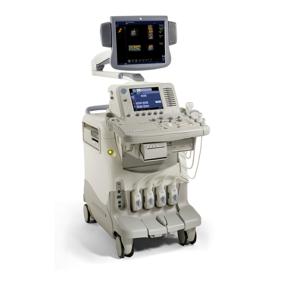
Page 63: Console Graphics
Console Overview Console graphics The following are illustrations of the console: Figure 3-1. LOGIQ 7 System (right and left side views) 1. Probe and Gel Bottle Holder 2. Storage area of Peripheral Device 3. Storage area of Peripheral Device (located beneath the... - Page 64 Preparing the System for Use Console graphics (continued) Figure 3-2. LOGIQ 7 System (front and back views) 1. Optional B/W Video Page Printer 2. Footswitch connector 3. External Disk Drive and Optional Physiological Input Panel - DVD Multi Drive and ECG...
- Page 65 Make sure that the DVD Multi Drive Disk tray and/or MO Disk CAUTION are securely placed in each device during system operation. Mechanical damage may occur if other objects hit the tray or MO disk. LOGIQ 7 Basic User Manual Direction 2392206-100 Rev. 1...
- Page 66 Figure 3-3. Storage Areas 1. Storage Areas DO NOT place probes or the footswitch into either the side CAUTION pocket or the peripheral device’s storage area. LOGIQ 7 Basic User Manual Direction 2392206-100 Rev. 1...
- Page 67 1. Task lamp 2. Light Volume Control knob Adjust the knob clockwise to increase the light’s brightness. Adjust the knob counterclockwise to dim the light. Figure 3-5. Task Lamp Light Control knob LOGIQ 7 Basic User Manual Direction 2392206-100 Rev. 1...
-
Page 68: Peripheral/Accessory Connection
Preparing the System for Use Peripheral/Accessory Connection Peripheral/Accessory Connector Panel LOGIQ 7 peripherals and accessories can be properly connected using the rear connector panel located behind the rear door. Only the B/W Printer can be connected to the front accessory panel. - Page 69 The connection of equipment or transmission networks other CAUTION than as specified in these instructions can result in electric shock hazard. Alternate connections will require verification of compatibility and conformity to IEC/EN 60601-1-1 by the installer. LOGIQ 7 Basic User Manual Direction 2392206-100 Rev. 1...
- Page 70 Audio In/Out S-Video In Camera Color/Camera Shrinked D-Sub, 15-pin Service USB(A) VCR 1 USB(A) VCR 2 USB(A) For Future use Insite RJ-11 Modular, 6-pin Ethernet RJ-45 Modular, 8-pin Power IEC Couplers LOGIQ 7 Basic User Manual Direction 2392206-100 Rev. 1...
- Page 71 Console Overview Front Panel Located on the front panel are Microphone, LED, and Reset. Serial Figure 3-7. Front Panel 1. Microphone 3. Serial 2. LED (HD access) 4. Reset LOGIQ 7 Basic User Manual Direction 2392206-100 Rev. 1...
- Page 72 DO NOT place or store the footswitch in the side pocket or the CAUTION Peripheral Device storage area on the system. This is to prevent the possibility of the footswitch falling and damaging itself. LOGIQ 7 Basic User Manual Direction 2392206-100 Rev. 1...
-
Page 73: Connecting And Using The System
5. Push the power plug securely into the wall outlet. Use caution to ensure that the power cable does not CAUTION disconnect during system use. If the system is accidentally unplugged, data may be lost. LOGIQ 7 Basic User Manual Direction 2392206-100 Rev. 1... - Page 74 To help assure grounding reliability, connect to a “hospital grade” or “hospital only” grounded power outlet. Figure 3-10. Example Plug and Outlet Configurations 100-120 VAC, 1200 VA Plug and Outlet Configuration 220-240 VAC, 1200 VA Plug and Outlet Configuration LOGIQ 7 Basic User Manual Direction 2392206-100 Rev. 1...
- Page 75 After being transported, the unit requires one hour for each 2.5° increment its temperature is below 10° C or above 40° C. Table 3-3: System Acclimation Time Chart ° C ° F hours ° C ° F hours LOGIQ 7 Basic User Manual Direction 2392206-100 Rev. 1...
- Page 76 Press the Power On/Off switch to turn the power on. The CAUTION circuit breaker must also be in the on position. For circuit breaker location, see Figure 3-14. Figure 3-11. Power On/Off Switch Location LOGIQ 7 Basic User Manual Direction 2392206-100 Rev. 1...
- Page 77 Peripheral devices are activated on power up. After initialization is complete, all lighted buttons on the Control Panel light and the default B-Mode screen or Patient screen (no probes are connected) is displayed in the monitor display. LOGIQ 7 Basic User Manual Direction 2392206-100 Rev. 1...
- Page 78 Cancel: Cancel logon If the correct ID and Password are entered, the system displays the Patient screen. Logoff To logoff, press the Power On/Off switch momentarily and a SYSTEM-EXIT window appears. LOGIQ 7 Basic User Manual Direction 2392206-100 Rev. 1...
- Page 79 If the Power On/Off switch is pressed too long, the system shuts down instead of coming out of Standby Mode. NOTE: It takes about four hours to fully recharge the battery. LOGIQ 7 Basic User Manual Direction 2392206-100 Rev. 1...
- Page 80 Power On LED is off. NOTE: When the Uninterruptible Power Supply (UPS) is installed, battery replacement may be necessary if the circuit breaker is turned off for long periods of time (3 to 6 months). LOGIQ 7 Basic User Manual Direction 2392206-100 Rev. 1...
- Page 81 2. Call Service immediately. DO NOT attempt to use the system. Figure 3-14. Location of Circuit Breaker 1. Circuit Breaker On position 2. Circuit Breaker Off position 3. Circuit Breaker location LOGIQ 7 Basic User Manual Direction 2392206-100 Rev. 1...
-
Page 82: Moving The System
Please ensure that the peripheral devices, which are CAUTION installed in the storage areas, are secured with the supplied straps. LOGIQ 7 Basic User Manual Direction 2392206-100 Rev. 1... - Page 83 10. Adjust the monitor and control panel to its lowest position possible by using the release lever located underneath the control panel. Make sure the keyboard is locked in place. 11. Unlock the wheels. LOGIQ 7 Basic User Manual Direction 2392206-100 Rev. 1...
- Page 84 • Be sure the pathway is clear. • Limit movement to a slow careful walk. • Use two or more persons to move the system on inclines or long distances. LOGIQ 7 Basic User Manual Direction 2392206-100 Rev. 1...
-
Page 85: Transporting The System
Never ride on the lift with the system. A person's weight WARNING coupled with the weight of the system may exceed the load capacity of the lift. 7. Employ two to three persons to load and unload safely from a vehicle. LOGIQ 7 Basic User Manual Direction 2392206-100 Rev. 1... - Page 86 10. Secure system with straps or as directed otherwise to prevent motion during transport. 11. Prevent vibration damage by driving cautiously. Avoid unpaved roads, excessive speeds, and erratic stops or starts. LOGIQ 7 Basic User Manual Direction 2392206-100 Rev. 1...
-
Page 87: Wheels
Figure 3-16. Front Pedal Table 3-4: Front Pedal Functions Pedal position Function Left Swivel Lock Center 4 Free wheels Right Park LOGIQ 7 Basic User Manual Direction 2392206-100 Rev. 1... - Page 88 When two or more people are releasing the swivel/pivot wheel CAUTION controls with the front and rear pedals, take extra precaution to prevent unexpected movement which could result in possible toe injuries. LOGIQ 7 Basic User Manual Direction 2392206-100 Rev. 1...
-
Page 89: Rotate, Tilt, Raise And Lower The Monitor
The monitor and console panel can be raised or lowered for the best viewing height. NOTE: When moving the LOGIQ 7, lower and lock the monitor and console panel to its lowest possible position to improve stability. Be careful when lowering the monitor and control panel that it... - Page 90 CAUTION place BOTH hands on the control panel. Touching other moving parts other than the control panel many cause personal injury Figure 3-18. Position of hands when moving monitor and console LOGIQ 7 Basic User Manual Direction 2392206-100 Rev. 1...
-
Page 91: Brightness And Contrast
The proper setup displays a complete gray scale. The lowest level of black should just disappear into the background and the highest white should be bright, but not saturated. LOGIQ 7 Basic User Manual Direction 2392206-100 Rev. 1... - Page 92 1. Press the Toggle button on the display monitor twice. 2. Press the Adjustment (+) button to increase brightness. Press the Adjustment (-) button to decrease brightness. The amount of brightness is shown on a slide bar on the screen. LOGIQ 7 Basic User Manual Direction 2392206-100 Rev. 1...
- Page 93 Once set, the display then becomes the reference for the hard copy device(s). NOTE: After readjusting the monitor's Contrast and Brightness, readjust all preset and peripheral settings. LOGIQ 7 Basic User Manual Direction 2392206-100 Rev. 1...
-
Page 94: Manual Degauss
Speakers Audio is provided by speakers located on the sides of the display monitor. • Audio Doppler operation • Audio playback of videotaped scan sessions • Audio error notification. LOGIQ 7 Basic User Manual Direction 2392206-100 Rev. 1... -
Page 95: Introduction
• Begin the scan session using the default Power Output setting for the probe and exam. NOTE: Selecting a new probe unfreezes the image. LOGIQ 7 Basic User Manual Direction 2392206-100 Rev. 1... -
Page 96: Connecting The Probe
Fault conditions can result in electric shock hazard. Do not CAUTION touch the surface of probe connectors which are exposed when the probe is removed. Do not touch the patient when connecting or disconnecting a probe. LOGIQ 7 Basic User Manual Direction 2392206-100 Rev. 1... - Page 97 Align the connector of the adapter with the probe port and carefully push into place. Figure 3-20. Align the connector with the probe port Turn the connector locking handle clockwise to the full vertical position to lock in place. LOGIQ 7 Basic User Manual Direction 2392206-100 Rev. 1...
- Page 98 Carefully align the probe connector to the system and push it firmly into place. Turn the locking handle clockwise to secure the probe connector to the system. LOGIQ 7 Basic User Manual Direction 2392206-100 Rev. 1...
-
Page 99: Cable Handling
Probes Cable Handling Take the following precautions with probe cables: • Keep free from wheels • Do not bend the cable acutely • Avoid crossing cables between probes. LOGIQ 7 Basic User Manual Direction 2392206-100 Rev. 1... -
Page 100: Activating The Probe
• Ensure the cable is free. • Be sure that the probe head is clean before placing the probe in its storage box or a wall hanging unit. LOGIQ 7 Basic User Manual Direction 2392206-100 Rev. 1... - Page 101 Be sure that the probe head is clean before placing the probe in its case. Move the adapter locking handle counterclockwise into the horizontal position. Carefully slide the adapter away from the probe port. Store the adapter in its case. LOGIQ 7 Basic User Manual Direction 2392206-100 Rev. 1...
-
Page 102: Transporting Probes
NOT use excessive force or impact the probe head. DO NOT store probes in either the side pocket or the peripheral CAUTION device’s storage area on the system. To avoid damage, store the probe in its carrying case. LOGIQ 7 Basic User Manual Direction 2392206-100 Rev. 1... -
Page 103: Control Panel Map
Controls are grouped together by function for ease of use. See the callouts for this figure on the following page. Patient Depth Body Pattern Measure Ellipse Zoom Comment M/D Cursor Auto Clear Scan Area B Pause Freeze Figure 3-23. Control Panel LOGIQ 7 Basic User Manual Direction 2392206-100 Rev. 1... -
Page 104: Key Illumination
The keyboard area must have task lighting or equivalent to allow operation in a dark room. Table 3-6: Key Illumination Backlight Capability Availability Function is not available ON (Normal-intensity) Function is available ON (High-intensity) Activated/ON Blinking User input is requested LOGIQ 7 Basic User Manual Direction 2392206-100 Rev. 1... -
Page 105: Keyboard
Text1/Text2 (F8 Switch between user text annotation overlays. Key) Grab Last (F9 Key) Activate the last selected data for edit. Word Delete (F10 Erase word associated with comment cursor. Key) LOGIQ 7 Basic User Manual Direction 2392206-100 Rev. 1... -
Page 106: Touch Panel
The functionality of these rotaries changes, depending upon the currently displayed menu. Press the button to switch between controls (as with Focus Position/ Number), or rotate the dial to adjust the value. LOGIQ 7 Basic User Manual Direction 2392206-100 Rev. 1... - Page 107 5. Progression keys are used to assess the impact of the control on the image progressively. 6. Sub-menu keys are used to bring up an additional menu. LOGIQ 7 Basic User Manual Direction 2392206-100 Rev. 1...
-
Page 108: Mode, Display And Record
Freeze a second time continues live image data acquisition. • To activate a specific mode, press the appropriate mode key. Each mode has its own gain control via the larger gray knob surrounding the mode key. LOGIQ 7 Basic User Manual Direction 2392206-100 Rev. 1... -
Page 109: Measurement And Annotation
It also becomes the “mouse” arrow for making selections along with the Set key (to fix or finish a selection). When the Measure key is pressed, the measurement Touch Panel is displayed. LOGIQ 7 Basic User Manual Direction 2392206-100 Rev. 1... - Page 110 (e.g. to fix a measurement caliper). • The Trackball is used with almost every key function in this group. Trackball control depends on the last key function pressed. LOGIQ 7 Basic User Manual Direction 2392206-100 Rev. 1...
-
Page 111: Monitor Display
Monitor Display Monitor Display Monitor Display Figure 3-26. Monitor Display Tour LOGIQ 7 Basic User Manual Direction 2392206-100 Rev. 1... - Page 112 21. Service Interface icon (wrench), iLinq 10. Measurement Calipers. icon, and system messages display. 11. Measurement Results Window. 22. Trackball Functionality Status: Scroll, M&A (Measurement and Analysis), Position, Size, Scan Area Width and Tilt. LOGIQ 7 Basic User Manual Direction 2392206-100 Rev. 1...
-
Page 113: Chapter 4 - Preparing For An Exam
Chapter 4 Preparing for an Exam Describes how to begin an exam. LOGIQ 7 Basic User Manual Direction 2392206-100 Rev. 1... -
Page 114: Introduction
To avoid patient identification errors, always verify the CAUTION identification with the patient. Make sure the correct patient identification appears on all screens and hard copy prints. LOGIQ 7 Basic User Manual Direction 2392206-100 Rev. 1... -
Page 115: Beginning A New Patient
Exams and patients can always be erased later. NOTE: If the current patient does not exist, pressing Patient activates the Patient Search screen. NOTE: If the current patient exists, pressing Patient activates the Exam History screen. LOGIQ 7 Basic User Manual Direction 2392206-100 Rev. 1... - Page 116 Preparing for an Exam Patient Screen Figure 4-2. Patient Screen (Category: OB) LOGIQ 7 Basic User Manual Direction 2392206-100 Rev. 1...
- Page 117 2. Category Selection • Select from 8 exam application categories: Abdomen, Obstetrics, Gynecology, Cardiology, Vascular, Urology, Small Parts or Pediatrics. When a category is selected, the measurement and category presets are displayed. LOGIQ 7 Basic User Manual Direction 2392206-100 Rev. 1...
- Page 118 Figure 4-3. Review and Continue Exam • New Exam–Used to create a new exam on a current patient. • Delete–Delete Patient/Exam. • Exit–Used to exit Patient Menu. 4. Dataflow Selection • Select the appropriate dataflow. LOGIQ 7 Basic User Manual Direction 2392206-100 Rev. 1...
- Page 119 • Detail–Select the Detail box to activate/deactivate the exam details. Exam details include Indications, Comments, Admission Number, Perf. Physician’s Telephone Number, Ref. Physician’s Telephone Number and Operator Telephone Number. LOGIQ 7 Basic User Manual Direction 2392206-100 Rev. 1...
- Page 120 “Use Hide key to unhide” displays until Hide is again selected. • Showing XX/XX–Displays the searched (selected) patients (number of patients currently displayed on the list/number of patients in the database). • Showing All–Displays all patients in the database. LOGIQ 7 Basic User Manual Direction 2392206-100 Rev. 1...
- Page 121 8. Select the probe from the Touch Panel to start scanning (or select Exit, Escape, Scan, or Freeze). 9. Perform the exam. 10. When you have completed the study, press End Exam, End Current Patient, then Store All Images Permanently. LOGIQ 7 Basic User Manual Direction 2392206-100 Rev. 1...
- Page 122 2. Select the patient from Patient List. 3. Press New Exam. Figure 4-5. Warning Message The following message displays “Do you want to create today’s exam for the patient?”. 4. Select Yes to start a new exam. LOGIQ 7 Basic User Manual Direction 2392206-100 Rev. 1...
- Page 123 3. Press Patient to display the Patient Search screen. 4. Enter the Patient ID. 5. Enter patient data and exam information as necessary. 6. Press Active Images. 7. Press Permanent Store. LOGIQ 7 Basic User Manual Direction 2392206-100 Rev. 1...
-
Page 124: Retrieving And Editing Archived Information
Click ‘+’ mark on the left side of Patient ID, then all exams of the patient is displayed in the patient list. Select the required exam and press Active Images. The image list of the exam is displayed. LOGIQ 7 Basic User Manual Direction 2392206-100 Rev. 1... - Page 125 Beginning an Exam Searching for an existing patient (continued) 5. The selected patient exam screen is displayed. Figure 4-7. Patient Exam Screen LOGIQ 7 Basic User Manual Direction 2392206-100 Rev. 1...
- Page 126 1. Search the patient by using Patient Search Field. 2. Move the cursor to the patient and press Set. 3. Select Review. 4. The Patient Exam screen is displayed. Figure 4-8. Patient Exam Screen LOGIQ 7 Basic User Manual Direction 2392206-100 Rev. 1...
- Page 127 Figure 4-9. Patient Select pop-up Menu 6. Select the exam and press “Images” in the Past Exam Information field, the thumbnail images are displayed. Press “Images” again to return. Figure 4-10. Images Information (Example) LOGIQ 7 Basic User Manual Direction 2392206-100 Rev. 1...
- Page 128 1. Select the exam which includes the image to review. 2. Press Active Images. 3. Select the image and press Review. Figure 4-11. Active Images Screen 4. The image is displayed. LOGIQ 7 Basic User Manual Direction 2392206-100 Rev. 1...
- Page 129 2. ‘Active Exam’ is displayed on the green button. Figure 4-12. Image History Screen 3. Move the cursor to the required image. 4. Press Review. 5. The selected image is displayed. LOGIQ 7 Basic User Manual Direction 2392206-100 Rev. 1...
- Page 130 3. The patient exam screen is displayed. Select the exam which you want to delete. 4. The confirmation dialog box is displayed. Figure 4-14. Delete Exam Confirmation Dialog Box 5. Press OK to delete or Cancel. LOGIQ 7 Basic User Manual Direction 2392206-100 Rev. 1...
- Page 131 5. Select the image to delete and press Delete. 6. The confirmation dialog box is displayed. Figure 4-15. Delete Image Confirmation Dialog Box 7. Press Yes to delete or No to cancel. LOGIQ 7 Basic User Manual Direction 2392206-100 Rev. 1...
- Page 132 If patient information needs to be edited or the exam category changed, use the New Exam feature. Pressing New Exam allows modification of the Patient Screen without erasing accumulated patient images, measurements, annotations, calculations and worksheets. LOGIQ 7 Basic User Manual Direction 2392206-100 Rev. 1...
- Page 133 Select “No” to create a new exam for the patient. 6. To display the patient information on the title bar, press the Esc key or the B-Mode key. Select the Preset and appropriate probe Touch Panel keys, if necessary. LOGIQ 7 Basic User Manual Direction 2392206-100 Rev. 1...
-
Page 134: Selecting An Application Preset And A Probe
The factory default preset selections are displayed on the Touch Panel. A typical example for the Abdomen exam category is shown below. Figure 4-18. Abdomen Preset Selection Touch Panel Use these parameters as a starting point for the exam. LOGIQ 7 Basic User Manual Direction 2392206-100 Rev. 1... - Page 135 To set up User-Defined Application Presets, 1. From the Touch Panel, press the Preset icon at the top of the Touch Panel. The Preset Touch Panel appears: Figure 4-19. Preset Touch Panel LOGIQ 7 Basic User Manual Direction 2392206-100 Rev. 1...
- Page 136 Figure 4-21. Create New User Application Menu NOTE: The new user application is based upon the current exam category and application, plus any modifications you have made, including the comment library and M&A calcs. LOGIQ 7 Basic User Manual Direction 2392206-100 Rev. 1...
- Page 137 Figure 4-22. Create New User Application Menu The new application now appears on the Touch Panel. Figure 4-23. New User Application NOTE: You can set up to four (4) user-defined application presets for each exam category. LOGIQ 7 Basic User Manual Direction 2392206-100 Rev. 1...
- Page 138 NOTE: Currently, there is no way to delete a user-defined application. LOGIQ 7 Basic User Manual Direction 2392206-100 Rev. 1...
- Page 139 Always start out with a probe that provides optimum focal depths and penetration for the patient size and exam. • Begin the scan session using the default Power Output setting for the probe and exam. Figure 4-25. Probe Indicators (Example) LOGIQ 7 Basic User Manual Direction 2392206-100 Rev. 1...
- Page 140 Preparing for an Exam LOGIQ 7 Basic User Manual Direction 2392206-100 Rev. 1...
-
Page 141: Chapter 5 - Optimizing The Image
Chapter 5 Optimizing the Image Describes how to adjust the image. This chapter is broken into the following sections: B-Mode, M-Mode, Color Flow Mode, Doppler Mode, and 3D Mode. LOGIQ 7 Online Help Direction 2392536-100 Rev. 1... -
Page 142: Intended Uses
Optimizing the Image Optimizing B-Mode Intended Uses B-Mode is intended to provide two-dimensional images and measurement capabilities concerning the anatomical structure of soft tissue. Figure 5-1. B-Mode Display LOGIQ 7 Online Help Direction 2392536-100 Rev. 1... - Page 143 Perform the scan. Add important data to the image: annotations and measurements. Record results: print hard copies, CINE review/optimize image capture, and VCR recording. 3. Complete the study by collecting all the data. LOGIQ 7 Online Help Direction 2392536-100 Rev. 1...
-
Page 144: B-Mode Touch Panel
Optimizing the Image B-Mode Touch Panel Figure 5-2. B-Mode Touch Panel, Page 1 Figure 5-3. B-Mode Touch Panel Page 2 LOGIQ 7 Online Help Direction 2392536-100 Rev. 1... -
Page 145: B-Mode Scanning Hints
Focal zones must be moved to track at the center of the anatomy of interest. Scan Area. Sizes region of interest. Adjust the Scan Area to the smallest reasonable size to maximize frame rate. LOGIQ 7 Online Help Direction 2392536-100 Rev. 1... -
Page 146: Depth
Changing the depth may change the TI and/or MI. Observe the output display for possible effects. Make sure enough space is left below the anatomy of interest HINTS to demonstrate shadowing or enhancement. LOGIQ 7 Online Help Direction 2392536-100 Rev. 1... -
Page 147: Gain
Gain has no affect on Power Output. However, with increased gain, the power output level can usually be reduced to produce an equivalent image quality. NOTE: Always optimize gain before increasing the Power Output. LOGIQ 7 Online Help Direction 2392536-100 Rev. 1... -
Page 148: Focus
Changing the focal number affects the frame rate. The greater controls number of focal zones, the slower the frame rate. Bioeffects Changing the focal zone may change the TI and/or MI. Observe the output display for possible effects. LOGIQ 7 Online Help Direction 2392536-100 Rev. 1... -
Page 149: Auto Optimize (Auto)
Trackball to position M/D-Mode cursor. Values On/Off. Benefits Lets you position the cursor before you go into M-Mode or Doppler Mode so that you can make optimum use of the larger B-Mode image. LOGIQ 7 Online Help Direction 2392536-100 Rev. 1... -
Page 150: B Flow
Turn off the background when imaging the kidney, liver, and spleen. Keep the focal zone as close to flow as possible. It is beneficial to narrow the sector width and increase the frame rate. LOGIQ 7 Online Help Direction 2392536-100 Rev. 1... - Page 151 When you select B Flow, the PRF increases. Adjusting the following controls may affect the Power Output: Focal Zone Position, Depth, Zoom, Line Density, Scan Area, Frequency, or angle steer. Observe the output display for possible effects. LOGIQ 7 Online Help Direction 2392536-100 Rev. 1...
-
Page 152: Crossbeam
To adjust the number of frames being compounded, press the CrossBeam# Touch Panel key. Select Low or High. You can preset CrossBeam to activate upon entering B-Mode; you can also preset the CrossBeam # via the Utility, Imaging, B- Mode page. LOGIQ 7 Online Help Direction 2392536-100 Rev. 1... - Page 153 Therefore, this technique can improve contrast resolution with increased conspicuity of low contrast lesions, better detection of calcifications, biopsy needle visualization, and cystic boundary definition. LOGIQ 7 Online Help Direction 2392536-100 Rev. 1...
-
Page 154: Coded Harmonic Imaging (Chi)
Coded Harmonics may improve B- Mode image quality without introducing a contrast agent. Bioeffects Activating multi frequency mode may change the TI and/or MI. Observe the output display for possible effects. LOGIQ 7 Online Help Direction 2392536-100 Rev. 1... -
Page 155: Frequency
This optimizes the probe's wide band imaging capabilities at multiple frequencies to image at greater depths. Bioeffects Activating multi frequency mode may change the TI and/or MI. Observe the output display for possible effects. LOGIQ 7 Online Help Direction 2392536-100 Rev. 1... -
Page 156: Virtual Convex
When you change the depth, TGC is rescaled across the new depth range. Each pot is proportionately scaled across the depth. Benefits TGC balances the image so that the density of echoes is the same throughout the image. LOGIQ 7 Online Help Direction 2392536-100 Rev. 1... -
Page 157: Scan Area
Bioeffects Steering the sector angle may change the TI and/or MI. Observe the output display for possible effects. LOGIQ 7 Online Help Direction 2392536-100 Rev. 1... -
Page 158: Dynamic Range (Compression)
Calcs, or New Patient. Benefits Used for anatomical correctness. When reading a reverse image, be careful to observe the probe CAUTION orientation to avoid possible confusion over scan direction or left/right image reversal. LOGIQ 7 Online Help Direction 2392536-100 Rev. 1... -
Page 159: Line Density
Affect on other Line density changes the vector density and frame rate. controls Bioeffects Activating color flow line density may change the TI and/or MI. Observe the output display for possible effects. LOGIQ 7 Online Help Direction 2392536-100 Rev. 1... -
Page 160: Map
Assigns a lesser amount of gray scale pixel values to weak reflections in the image than Map C. Useful when imaging abdomen and liver. LOGIQ 7 Online Help Direction 2392536-100 Rev. 1... - Page 161 S-shaped map. This map highlights tissue differentiation for a certain band of signals. Useful when imaging structures where you want more contrast, e.g., cardiology. LOGIQ 7 Online Help Direction 2392536-100 Rev. 1...
-
Page 162: Frame Average
Benefits Allows you to use a higher frequency in the abdominal application on technically difficult patients. Bioeffects Changing the focal zone may change the MI. Observe the output display for possible effects. LOGIQ 7 Online Help Direction 2392536-100 Rev. 1... -
Page 163: Colorize
The gray bar displays while Colorize is activated. Adjusting To activate Colorize, 1. Select Colorize on the Touch Panel. 2. Trackball to cycle through available maps. 3. Press Set to select. To deselect, select a gray map. LOGIQ 7 Online Help Direction 2392536-100 Rev. 1... -
Page 164: Edge Enhance
Category, Exam Calcs, or New Patient. Benefits Beneficial in transvaginal and transrectal scanning. When reading an rotated image, be careful to observe the CAUTION probe orientation to avoid possible confusion over scan direction or left/right image reversal. LOGIQ 7 Online Help Direction 2392536-100 Rev. 1... -
Page 165: Rejection
Dual Beam Description Two receiving beams are formed from one transmitting beam. High frame rate is realizable. Adjusting On/Off. NOTE: Set Duam Image on the Utility -> Imaging -> B-Mode preset page. LOGIQ 7 Online Help Direction 2392536-100 Rev. 1... -
Page 166: Contrast Imaging
Clinical Use Possible clinical uses are to detect and characterize tumors of the liver, kidney, and pancreas and to enhance flow signals in the determination of stenosis or thrombus. LOGIQ 7 Online Help Direction 2392536-100 Rev. 1... - Page 167 Press the Contrast key on the Control Panel. B-Mode Contrast activates in the B fundamental frequency. Figure 5-4. B Mode Contrast Imaging, Page 1 Figure 5-5. B Mode Contrast Imaging Touch Panel, Page 2 LOGIQ 7 Online Help Direction 2392536-100 Rev. 1...
- Page 168 Optimizing the Image Contrast Imaging Overview (continued) To activate TruAgent Detection, press the Touch Panel key. Figure 5-6. TruAgent Detection Contrast Imaging, Page 1 Figure 5-7. TruAgent Detection Contrast Imaging, Page 2 LOGIQ 7 Online Help Direction 2392536-100 Rev. 1...
- Page 169 Optimizing B-Mode Contrast Imaging Overview (continued) Figure 5-8. TruAgent Detection Contrast Imaging, Page 3 LOGIQ 7 Online Help Direction 2392536-100 Rev. 1...
- Page 170 Feature Multi Image and 3D are available; LOGIQView is not available. Availability Technique Use the table in Chapter 17 to determine which contrast Availability by technique is available by probe. Probe LOGIQ 7 Online Help Direction 2392536-100 Rev. 1...
- Page 171 Acoustic Output (%) to set the value. Additional Presets To adjust other TruAgent Detection Imaging presets (Line Density, Frame Average, etc.), press the down arrow to adjust the setting. See Chapter 16 for more information. LOGIQ 7 Online Help Direction 2392536-100 Rev. 1...
- Page 172 Adjusting Adjust the dial left/right. Values 1, 1.25, 1.5, 1.75 and 2. Benefits By using Sensitivity PRI, sensitivity can be changed for each anatomy of interest. LOGIQ 7 Online Help Direction 2392536-100 Rev. 1...
- Page 173 The timer also appears on CINE Loops and archived images. Benefits The Contrast Clock measures the time since injection. LOGIQ 7 Online Help Direction 2392536-100 Rev. 1...
- Page 174 Contrast Settings (Not Shown). The Acoustic Output setting for B Contrast is displayed here. The trigger status is displayed (0=Off, 1=On, plus the time interval). The Contrast Imaging Technique is displayed here (Fnd=Fundamental, CHA=Coded Harmonic Angio, PI=Phase Inversion, CPI=Coded Phase Inversion, TAD=TruAgent Detection. LOGIQ 7 Online Help Direction 2392536-100 Rev. 1...
-
Page 175: Time Intensity Curve (Tic) Analysis
LOGIQ 7 Online Help Direction 2392536-100 Rev. 1... - Page 176 The TIC package is only available when the system is in FREEZE mode. 3. TIC Analysis displays on the Cine Touch Panel. Figure 5-10. Cine Touch Panel NOTE: Subsequent TIC processing is done on the images stored in CINE memory. LOGIQ 7 Online Help Direction 2392536-100 Rev. 1...
- Page 177 Activating TIC (continued) 4. Select TIC Analysis. The TIC Analysis screen and Touch Panel displays. To toggle the trackball function between TIC and Scroll, press Scan Area. Figure 5-11. TIC Analysis Screen (TAD mode) LOGIQ 7 Online Help Direction 2392536-100 Rev. 1...
- Page 178 There are several methods to exit TIC Analysis. • Toggling Exit TIC Analysis on the TIC Touch Panel. • Press Freeze to unfreeze and resume scanning. • Press any other button that returns the system to real-time scanning. LOGIQ 7 Online Help Direction 2392536-100 Rev. 1...
- Page 179 Table 5-5: TIC Analysis Screen Description Contrast Cineloop Window Sample Area: Indicates sampling position of the intensity (Contrast) trace. The sample area is color-coded: the first sample area is yellow, the second green, etc. LOGIQ 7 Online Help Direction 2392536-100 Rev. 1...
- Page 180 Time at cursor position and velocity at cursor position. Sample Area Tools. • Pencil Icon : Creates a sample area based on freehand drawing. • Shape Icon : Creates a sample area with a pre-defined circular/ellipse shape. LOGIQ 7 Online Help Direction 2392536-100 Rev. 1...
- Page 181 Reference Image Position the cursor over the reference image and press the left System Menu Set key. The reference image system menu displays at the cursor position. Figure 5-15. Reference Image System Menu LOGIQ 7 Online Help Direction 2392536-100 Rev. 1...
- Page 182 Position the cursor on the Frame Marker in the Analysis Window System Menu and press the left Set key. The Frame Marker system menu displays at the cursor position. Figure 5-17. Frame Marker System Menu LOGIQ 7 Online Help Direction 2392536-100 Rev. 1...
- Page 183 2. The last frame in the analysis series is selected by adjusting the CINE Last Frame control to the desired frame using the Trackball or the Frame by Frame control to select the desired last frame and then selecting the Last Frame control. LOGIQ 7 Online Help Direction 2392536-100 Rev. 1...
- Page 184 3. Press and hold down the Set key while drawing a sample are using the Trackball. 4. Release the Set key. The sample area is automatically closed and the trace is updated accordingly in the Analysis window. LOGIQ 7 Online Help Direction 2392536-100 Rev. 1...
- Page 185 8. Using the Trackball, scroll through the cineloop and control that the sample area follows the moving anatomical structure. 9. Add anchored sample areas in several frames to obtain a more accurate displacement of the sample area. LOGIQ 7 Online Help Direction 2392536-100 Rev. 1...
- Page 186 2. Release the Set key. To unzoom: 1. Press the left Set key in the Analysis window. The system menu displays. 2. Select Unzoom. LOGIQ 7 Online Help Direction 2392536-100 Rev. 1...
- Page 187 Figure 5-18. Sample Area Information Box 2. Select Height, Width and Tilt angle. 3. Select Set as default. The current ROI size is set as the default for subsequent Ellipse ROIs. LOGIQ 7 Online Help Direction 2392536-100 Rev. 1...
- Page 188 The caliper is then free for repositioning for another freehand ROI. NOTE: You cannot go outside the image boundary when drawing a freehand ROI. LOGIQ 7 Online Help Direction 2392536-100 Rev. 1...
- Page 189 2. The ROI system menu displays. Select Label sample area. The Label Dialog box displays. Figure 5-20. Label Dialog Box 3. Enter a name for the sample area. 4. Select OK. LOGIQ 7 Online Help Direction 2392536-100 Rev. 1...
- Page 190 NOTE: The corresponding traces for the deleted ROIs are erased from the plot. NOTE: Deleting an ROI causes the ROIs to be deleted from all frames in the analysis loop. LOGIQ 7 Online Help Direction 2392536-100 Rev. 1...
- Page 191 B-mode data is used to calculate the time-intensity curve values. • Acoustic—The system reverse the log compression function to provide un-log compressed data for the TIC analysis. Figure 5-22. Vertical Unit Pop-up menu LOGIQ 7 Online Help Direction 2392536-100 Rev. 1...
- Page 192 • Squares—Setting the results in a plot where small squares are displayed at each data point, and the squares are linked together by lines. Figure 5-24. Line style Pop-up menu LOGIQ 7 Online Help Direction 2392536-100 Rev. 1...
- Page 193 The default is the user selected image range. If the user has not yet selected a first and last frame, the first and last default frames from the displayed CINE loop are used. Figure 5-26. Horizontal Sweep LOGIQ 7 Online Help Direction 2392536-100 Rev. 1...
- Page 194 When smoothing is turned on, it applies to all traces in the plot window. 2. The smoothing filter list displays. Select the appropriate parameter. Figure 5-27. Smoothing Menu NOTE: If ‘dt’ is selected for Horizontal Scale, you cannot use Smoothing. LOGIQ 7 Online Help Direction 2392536-100 Rev. 1...
- Page 195 A (dB or AU) is the intensity from the contrast agent. • B (dB or AU) is the intensity from the tissue = baseline signal. NOTE: A + B is the initial intensity level. • k (1/s) is a time constant. LOGIQ 7 Online Help Direction 2392536-100 Rev. 1...
- Page 196 2. Position the cursor on the ECG trace and press Set. The system menu displays. 3. Select ECG tirggering. All frames in all heart cycles are disabled except for the selected and corresponding frames in the other heart cycles. LOGIQ 7 Online Help Direction 2392536-100 Rev. 1...
- Page 197 2. Select Enable all frames. 3. All disabled frames are re-enabled. Figure 5-29. Frame makers 1. Analysis Window 2. Frame markers axis 3. Enabled frame (Green) 4. Disabled frame (Red) 5. ECG 6. Current frame LOGIQ 7 Online Help Direction 2392536-100 Rev. 1...
- Page 198 Data for disabled frames are not be included in the exported trace file. NOTE: No TIC trace results are saved in the standard image database. NOTE: TIC trace results are now shown on the Worksheet. LOGIQ 7 Online Help Direction 2392536-100 Rev. 1...
- Page 199 Chapter 6 for reference. Printing TIC Data Press the appropriate print key in the TIC mode. The system capture a single still frame which consists of the plot, the reference image and user annotation. LOGIQ 7 Online Help Direction 2392536-100 Rev. 1...
-
Page 200: Logiqview
LOGIQView acquires images via leading edge vectors (and does not acquire slices, as in CINE). The image is being stored as you perform the scan and you can watch the LOGIQView as it is being acquired. LOGIQ 7 Online Help Direction 2392536-100 Rev. 1... - Page 201 The system accommodates a reasonable range of motion velocity. DO NOT make abrupt changes in speed of motion. Deeper scans generally require reduced speed. Bioeffects Activating LOGIQView has no affect upon Acoustic Output values. LOGIQ 7 Online Help Direction 2392536-100 Rev. 1...
-
Page 202: Intended Use
Focus Position, as needed. 6. Press Freeze to stop the M trace. 7. Record the trace to disk or to the hard copy device. 8. Press Freeze to continue imaging. 9. To exit, press M-Mode. LOGIQ 7 Online Help Direction 2392536-100 Rev. 1... -
Page 203: M-Mode Display
Displays Overall M-Mode Gain as ##dB. Depth Scale Indicator Image depth, in cm. Time Scale Eight speeds: 0-7. Major marker = 1 second. M-Mode Cursor Displays where the M-Mode Cursor is positioned. LOGIQ 7 Online Help Direction 2392536-100 Rev. 1... -
Page 204: M-Mode Touch Panel
Optimizing the Image M-Mode Touch Panel Figure 5-32. M-Mode Touch Panel, Page 1 Figure 5-33. M-Mode Touch Panel, Page 2 LOGIQ 7 Online Help Direction 2392536-100 Rev. 1... -
Page 205: Scanning Hints
You can speed up or slow down the timeline to see more or fewer occurrences over time. Bioeffects Changing the Sweep Speed may change the TI and/or MI. Observe the output display for possible effects. LOGIQ 7 Online Help Direction 2392536-100 Rev. 1... -
Page 206: Anatomical M-Mode
The M-Mode display changes according to a motion of the M cursor. Figure 5-34. Anatomical M Mode Activating To activate Anatomical M-Mode: Press the Anatomical M Touch Panel control. LOGIQ 7 Online Help Direction 2392536-100 Rev. 1... - Page 207 Mode or M-Mode image. Bioeffects Changing the Sweep Speed, Packet Size, Frame Rate/ Resolution, Zoom, PRF, and ROI size may change the TI and/or MI. Observe the output display for possible effects. LOGIQ 7 Online Help Direction 2392536-100 Rev. 1...
-
Page 208: M Color Flow Mode
Benefits Color Flow Mode and Color M-Mode are Doppler Modes intended to add color-coded qualitative information concerning the relative velocity and direction of fluid motion within the B- Mode or M-Mode image. LOGIQ 7 Online Help Direction 2392536-100 Rev. 1... - Page 209 Resolution, Zoom, PRF, and ROI size may change the TI and/or MI. Observe the output display for possible effects. Figure 5-35. M Color Flow, Page 1 Figure 5-36. M Color Flow, Page 2 LOGIQ 7 Online Help Direction 2392536-100 Rev. 1...
-
Page 210: Intended Use
5. Press Freeze to hold the image in memory. 6. Record color flow images as necessary. 7. If more definitive information is needed about flow, utilize the procedures described under Doppler Mode. LOGIQ 7 Online Help Direction 2392536-100 Rev. 1... -
Page 211: Activating Color Flow
Mode provides spectral information in a smaller area. Color Flow is also sometimes used as a stepping stone to Doppler. You use Color Flow to locate flow and vessels prior to activating Doppler. LOGIQ 7 Online Help Direction 2392536-100 Rev. 1... -
Page 212: Exiting Color Flow
Packet Size. Affects the amount of color Doppler sensitivity versus frame rate. Scan Area. Increases/decreases size of color window. Focus Position. The best focusing is at the focal zone location. Put focal zone(s) at the area of interest. LOGIQ 7 Online Help Direction 2392536-100 Rev. 1... -
Page 213: Color Flow Mode Touch Panel
Optimizing Color Flow Color Flow Mode Touch Panel Figure 5-38. Color Flow Mode Touch Panel, Page 1 Figure 5-39. Color Flow Mode Touch Panel, Page 2 LOGIQ 7 Online Help Direction 2392536-100 Rev. 1... -
Page 214: Gain
Changing the PRF may affect Power Output, frame rate, and controls wall filter. When you adjust the velocity scale, CINE memory is cleared. Bioeffects Changing the PRF range may change the TI and/or MI. Observe the output display for possible effects. LOGIQ 7 Online Help Direction 2392536-100 Rev. 1... -
Page 215: Wall Filter
The smaller the color window, the faster the frame rate and vice controls versa. Bioeffects Sizing the color window may change the TI and/or MI. Observe the output display for possible effects. LOGIQ 7 Online Help Direction 2392536-100 Rev. 1... -
Page 216: Invert (Color Invert)
Baseline values are returned to the factory or user preset value when you change the following: Probe, Exam Category, Exam Calcs, or New Patient. Benefits Unwraps the alias during color flow imaging. Higher velocities can be displayed without reversal of colors. LOGIQ 7 Online Help Direction 2392536-100 Rev. 1... -
Page 217: Angle Steer
Provides a Doppler cursor angle suitable for linear probe orientation. Beneficial in Peripheral Vascular to image carotids. Bioeffects Activating angle steer may change the TI and/or MI. Observe the output display for possible effects. LOGIQ 7 Online Help Direction 2392536-100 Rev. 1... -
Page 218: Color Flow Line Density
Velocity Maps (VL). Flow shown as blue away/red toward the probe. Velocity Variance Maps (VV). Provides a measure of turbulence (stenosis). Adds green to velocity maps. Benefits Shows the direction of the flow and highlights the higher velocity flows. LOGIQ 7 Online Help Direction 2392536-100 Rev. 1... -
Page 219: Threshold
Affect on other Trades off between frame rate and color quality. As the color controls quality increases, the frame rate may decrease and as the frame rate increases, the color image quality decreases. LOGIQ 7 Online Help Direction 2392536-100 Rev. 1... -
Page 220: Transparency Map
Duplex Off: Toggle live B-Mode and Color Flow Mode via B- Pause. Adjusting Select Duplex to adjust. Values On/Off Benefits Allows the user to have both PW and B-Mode active at the same time. LOGIQ 7 Online Help Direction 2392536-100 Rev. 1... -
Page 221: Ace
When you increase the packet size, you improve image quality at the expense of frame rate. Bioeffects Changing packet size may change the TI and/or MI. Observe the output display for possible effects. LOGIQ 7 Online Help Direction 2392536-100 Rev. 1... -
Page 222: Power Doppler Imaging (Pdi)
PDI or select a new mode. Values On/Off. Ten power (P0-P6 and P8-P10) and one direction PDI map (P7) is available. Benefits Since PDI does not display velocity, it does not aliase. LOGIQ 7 Online Help Direction 2392536-100 Rev. 1... - Page 223 PDI. Used in applications where sensitivity and angle independence is desired, but directional information is also required. Flow towards the transducer is red; flow away is dark blue to light blue. LOGIQ 7 Online Help Direction 2392536-100 Rev. 1...
- Page 224 Optimizing the Image PDI (Power Doppler Imaging) Mode Touch Panel Figure 5-41. PDI Mode Touch Panel, Page 1 Figure 5-42. PDI Mode Touch Panel, Page 2 LOGIQ 7 Online Help Direction 2392536-100 Rev. 1...
-
Page 225: Directional Power Doppler
If the image is aliasing, increase the PRF and reduce the Wall HINTS Filter. LOGIQ 7 Online Help Direction 2392536-100 Rev. 1... -
Page 226: Pulsatile Flow Detection Mode
To activate/deactivate PFD mode, press PFD on the Control Panel while scanning in CFM or PDI mode. While in PFD mode, PFD scale is displayed on the left side. Figure 5-43. PFD Screen (Example) LOGIQ 7 Online Help Direction 2392536-100 Rev. 1... - Page 227 Optimizing Color Flow Activating/deactivating PFD (continued) Figure 5-44. PFD Touch Panel (Page 1) Figure 5-45. PFD Touch Panel (Page 2) LOGIQ 7 Online Help Direction 2392536-100 Rev. 1...
- Page 228 Press Map and select the desired map from the menu. Values PF-1, PF-2, PF-3 and PF-4. Benefits Directional Map shows flow direction and pulsatility of the flow. Non-Directional Map shows pulsatility and non-pulsatility of the flow. LOGIQ 7 Online Help Direction 2392536-100 Rev. 1...
-
Page 229: Intended Use
PW Doppler examination. The site where PW Doppler data is derived appears graphically on the B-Mode image (Sample Volume Gate). The sample volume gate can be moved anywhere within the B-Mode image. LOGIQ 7 Online Help Direction 2392536-100 Rev. 1... - Page 230 11. Press Freeze to hold the trace in memory and stop imaging. Activate CINE Timeline, as necessary. See Chapter 6 for more information. 12. Perform measurements and calculations, as necessary. Refer to the Measurements and Calculations chapter for more information. LOGIQ 7 Online Help Direction 2392536-100 Rev. 1...
- Page 231 Triplex Mode is used to examine blood flow information in the vessels of the legs, arms, abdomen, neck, and heart. To Exit PW Doppler Mode, press CF, then PW. LOGIQ 7 Online Help Direction 2392536-100 Rev. 1...
-
Page 232: Doppler Display
When you view the PW Doppler spectrum and a B-Mode image with a 3.5 MHz probe, this means that you are viewing the image at 3.5 MHz and `Dopplering' at 2.5 MHz. LOGIQ 7 Online Help Direction 2392536-100 Rev. 1... -
Page 233: Doppler Mode Display
Angledisplays in red when the angle exceeds 60°. Velocities obtained when the angle is greater than 80° are displayed as asterisks (***). Spectral Invert INVERT appears when the spectral trace is inverted and the plus/minus signs (+/-) are reversed. LOGIQ 7 Online Help Direction 2392536-100 Rev. 1... - Page 234 Flow direction has a positive and negative indicator, noted in centimeters per Scale second (cm/sec). When the velocity scale is less than 10 cm/s, it is displayed to the first decimal point (4.6 rather than 5 cm/s). LOGIQ 7 Online Help Direction 2392536-100 Rev. 1...
-
Page 235: Doppler Mode Scanning Hints
Dynamic Range. Affects the amount of Doppler amplitude data displayed. Wall Filter. Removes the noise caused by vessel or heart wall motion at the expense of low flow sensitivity. Sweep Speed. Controls speed of spectral update. LOGIQ 7 Online Help Direction 2392536-100 Rev. 1... -
Page 236: Doppler Mode Touch Panel
Optimizing the Image Doppler Mode Touch Panel Figure 5-47. PW Mode Touch Panel, Page 1 Figure 5-48. PW Mode Touch Panel, Page 2 LOGIQ 7 Online Help Direction 2392536-100 Rev. 1... -
Page 237: B Pause
Values On/Off. Benefits Update increases the Spectral Doppler display quality. Bioeffects Activating Update may change the TI and/or MI. Observe the output display for possible effects. LOGIQ 7 Online Help Direction 2392536-100 Rev. 1... -
Page 238: Doppler Sample Volume Gate Position (Trackball)
You can also enlarge the gate to hear the Doppler audio better or for sampling large vessels or areas. Bioeffects Changing the sample volume gate size may change the TI and/ or MI. Observe the output display for possible effects. LOGIQ 7 Online Help Direction 2392536-100 Rev. 1... -
Page 239: Prf
When you adjust the velocity scale, CINE memory is cleared. Adjustments may affect sample volume size and Doppler wall filter. Bioeffects Changing the velocity range may change the TI and/or MI. Observe the output display for possible effects. LOGIQ 7 Online Help Direction 2392536-100 Rev. 1... -
Page 240: Angle Correct
Quick Angle Description Quickly adjusts the angle by 60 degrees. Adjusting To quickly adjust the angle, press Quick Angle. Values 0 degrees and 60 degrees. LOGIQ 7 Online Help Direction 2392536-100 Rev. 1... -
Page 241: Wall Filter
Probe, Exam Category, Exam Calcs, or New Patient. Benefits Unwraps the alias. Rearranges the velocity scale without changing the velocity scale. Readjusts the positive and negative velocities limit without changing the total velocity range. LOGIQ 7 Online Help Direction 2392536-100 Rev. 1... -
Page 242: M/D Cursor
Benefits Provides a Doppler cursor angle suitable for linear probe orientation. Beneficial in Vascular applications. Bioeffects Activating angle steer may change the TI and/or MI. Observe the output display for possible effects. LOGIQ 7 Online Help Direction 2392536-100 Rev. 1... -
Page 243: Audio Volume
It is easier in cases like this to invert the spectrum instead of reversing the probe orientation. Affect on other The polarity of Doppler Audio is also reversed. controls LOGIQ 7 Online Help Direction 2392536-100 Rev. 1... -
Page 244: Dynamic Range
SELECT TRACE lets you indicate whether cardiac cycle Position detection, and therefore cardiac cycle identification, should use peak timeline data above, below, or above and below (composite) the baseline. Benefits Broadening may indicate turbulence. LOGIQ 7 Online Help Direction 2392536-100 Rev. 1... -
Page 245: Trace Sensitivity
Duplex Off: toggle live B-Mode + PW Mode via B Pause. Adjusting Press Duplex. Values On/Off. Benefits Allows you to have both B-Mode and PW Doppler Mode active at the same time. LOGIQ 7 Online Help Direction 2392536-100 Rev. 1... -
Page 246: Trace Direction
Adjusting Press Time Resolution. Values Benefits Time Resolution = 3 (high) smooths the Timeline; Time Resolution =1 (low) increases the time resolution (image not as smooth). LOGIQ 7 Online Help Direction 2392536-100 Rev. 1... -
Page 247: Spectral Average
This has the effect of presenting a smoother and softer image. Modify Auto Calcs Description Activates the menu to select which calculations are automatically calculated. Adjusting Press Modify Auto Calcs to activate Modify Auto Calcs Touch Panel. Benefits Provides flexibility. LOGIQ 7 Online Help Direction 2392536-100 Rev. 1... -
Page 248: Continuous Wave Doppler (Cwd)
Doppler spectrum (shown below in the B-Mode image) and listening to the Doppler Audio signal. Works with Sector probes. Figure 5-49. CWD Screen LOGIQ 7 Online Help Direction 2392536-100 Rev. 1... - Page 249 Provides only Doppler Spectrum and Audio for ascending/ descending aortic arch, other hard-to-get-to spaces or higher velocities. Requires a single CWD probe and probe adapter. Works with the P2D and P6D probes. Figure 5-50. Non Imaging CWD Screen LOGIQ 7 Online Help Direction 2392536-100 Rev. 1...
- Page 250 The Doppler spectrum displays along with the B-Mode image. (Steerable CW Doppler, NOT Non-Imaging CW Doppler). The cursor changes to a Doppler cursor. Figure 5-51. CWD Mode Touch Panel, Page 1 Figure 5-52. CWD Mode Touch Panel, Page 2 LOGIQ 7 Online Help Direction 2392536-100 Rev. 1...
- Page 251 Optimizing Spectral Doppler Exiting CW Doppler CW Doppler Mode, press CW. LOGIQ 7 Online Help Direction 2392536-100 Rev. 1...
-
Page 252: Overview
Easy 3D, Movie Mode images, e.g., Baby Face scans. Advanced 3D Designed for No sensor 3D Acquisition, rendering B Easy 3D, Mode and Color Advanced 3D, Flow Mode Movie images, e.g., vessel trees. LOGIQ 7 Online Help Direction 2392536-100 Rev. 1... -
Page 253: 3D Acquisition
Adjust the 3D dataset brightness with B-Mode or Color Flow Mode Gain. Use Colorize to change the color of the active dataset. Use Zoom to increase the zoom factor of the active dataset. LOGIQ 7 Online Help Direction 2392536-100 Rev. 1... - Page 254 Press right Set key when the white pointer Forward/Backward finger is positioned on the white box. Move the closed white hand to manipulate the 3D VOI. Figure 5-53. Manipulating the 3D Volume of Interest (White Hand) LOGIQ 7 Online Help Direction 2392536-100 Rev. 1...
- Page 255 Move the closed red hand to move through the 3D VOI. Figure 5-54. Moving through a 3D Volume of Interest (Red Hand) NOTE: Any plane in the volume can be made active (highlighted with red box) by clicking on it. LOGIQ 7 Online Help Direction 2392536-100 Rev. 1...
- Page 256 This actually moves an edge. A yellow hand appears only when the pointer is on an edge of the VOI. Figure 5-55. Manipulating the Edge of a 3D Volume of Interest (Yellow Hand) LOGIQ 7 Online Help Direction 2392536-100 Rev. 1...
- Page 257 View Specific positioned on the green box. Move the closed green hand to Anatomy manipulate the 3D VOI. Figure 5-56. Manipulating a Corner of the 3D Volume of Interest (Green Hand) LOGIQ 7 Online Help Direction 2392536-100 Rev. 1...
- Page 258 The values for opacity and threshold of the texture mode are set automatically according to the datasets histogram. The B-Mode image is rendered in the gray surface mode. Opacity and threshold values are defined according to the histogram. LOGIQ 7 Online Help Direction 2392536-100 Rev. 1...
- Page 259 You can adapt the form of a fetal face if the baby’s head looks oval instead of round. The assumed default width of a parallel scan is 6 cm; of a fan scan 60 degrees. LOGIQ 7 Online Help Direction 2392536-100 Rev. 1...
- Page 260 As soon as the Apply button is pressed, a new dataset is generated. Gray Surface Activates the gray surface rendering mode. It leads to a transparent appearance of the object, generated by displaying only a surrounding shell of structures. LOGIQ 7 Online Help Direction 2392536-100 Rev. 1...
- Page 261 A high opacity value leads to a transparent appearance of the rendered image. Colorize/Contrast Colorizes the 3D render or adds contrast to the 3D rendered image. LOGIQ 7 Online Help Direction 2392536-100 Rev. 1...
- Page 262 After selecting Visible Data, a list of data is displayed, Gray Data, Red, Blue. Choose the data you want to display. For example, if only color data is chosen, the B-Mode image is switched off in the rendered image and only vessel structures are displayed. LOGIQ 7 Online Help Direction 2392536-100 Rev. 1...
- Page 263 Set key. A plane can be moved parallel in the VOI by pressing the right Set key on the position of the green point and moving the Trackball up and down inside the plane. LOGIQ 7 Online Help Direction 2392536-100 Rev. 1...
- Page 264 You can adjust the speed of any 3D rotation. Pause Stops and restarts the rotation. As soon as Pause is pressed, the different rotation steps can be displayed by moving the Trackball. LOGIQ 7 Online Help Direction 2392536-100 Rev. 1...
-
Page 265: Chapter 6 - Scanning/Display Functions
Chapter 6 Scanning/Display Functions Describes additional ways in which to adjust the image. In addition, describes additional ways to get useful information electronically. LOGIQ 7 Basic User Manual Direction 2392206-100 Rev. 1... -
Page 266: Introduction
To zoom an image, adjust Zoom. A reference image appears in the upper, left-hand section of the display. To exit zoom, adjust Zoom until the reference zoom image is removed or press B-Mode. LOGIQ 7 Basic User Manual Direction 2392206-100 Rev. 1... - Page 267 Write Zoom uses a telephoto lens to bring the image closer before taking the picture. First use the Read Zoom (turn knob) to get to the area of HINTS interest, then use Write Zoom (press knob). LOGIQ 7 Basic User Manual Direction 2392206-100 Rev. 1...
-
Page 268: Introduction
To reactivate the image, 1. Press Freeze again. NOTE: Deactivating Freeze erases all measurements and calculations from the display (but not from the worksheet). Use the Trackball to start CINE after pressing Freeze. LOGIQ 7 Basic User Manual Direction 2392206-100 Rev. 1... - Page 269 Freezing an Image Freezing an Image (Footswitch Option) You can also freeze the image via the footswitch. LOGIQ 7 Basic User Manual Direction 2392206-100 Rev. 1...
-
Page 270: Post Processing
• Packet Size • • Dynamic Range NOTE: Color cannot be added to a black and white image that has been frozen. Auto Optimize. Optimizes the B-Mode image or Doppler Spectrum. LOGIQ 7 Basic User Manual Direction 2392206-100 Rev. 1... -
Page 271: Introduction
CINE is useful for focusing on images during a specific part of the heart cycle or to view short segments of a scan session. Activating CINE To activate CINE, 1. Press Freeze. 2. Move the Trackball. LOGIQ 7 Basic User Manual Direction 2392206-100 Rev. 1... -
Page 272: Cine And Monitor Display
The CINE display (located on the left-hand side of the monitor) indicates which frame you are viewing of the whole loop (62:123), as well as the time at which this frame occurs within the loop (1.6:3.2 s). Figure 6-1. CINE Display LOGIQ 7 Basic User Manual Direction 2392206-100 Rev. 1... -
Page 273: Using Cine
Figure 6-2. CINE Touch Panel Adjusting CINE Loop Speed Adjust the Loop Speed control at the bottom of the Touch Panel. Disconnecting B-Mode CINE from Timeline CINE Select B-Mode or Timeline CINE. LOGIQ 7 Basic User Manual Direction 2392206-100 Rev. 1... -
Page 274: Introduction
This assigns the trackball function to controlling the cursor and displays the annotation library on the Touch Panel menu. Figure 6-3. Comment Key on the Front Panel LOGIQ 7 Basic User Manual Direction 2392206-100 Rev. 1... - Page 275 To delete all annotations and arrow marks, press the Clear key twice immediately after entering the annotation mode. To end the Comment/Library Annotation function, press Set. To move by words or by text group, press the Tab key. LOGIQ 7 Basic User Manual Direction 2392206-100 Rev. 1...
-
Page 276: Adding Comments To An Image
F2 (Arrow) key. NOTE: This action clears the arrows only, not the comments on the screen. To erase all annotations as well as arrows, press the Clear key right after the Comment key. LOGIQ 7 Basic User Manual Direction 2392206-100 Rev. 1... - Page 277 To show the presence of a small list stored under a particular key, a small indicator (>) is placed on the key. To program your system with specific annotations, See ‘Annotations Libraries Presets’ for more information. LOGIQ 7 Basic User Manual Direction 2392206-100 Rev. 1...
- Page 278 Place the cursor on the desired text or text group and press Set. • The selected text color turns to green. • Use the Trackball to move the selected text and press Set. LOGIQ 7 Basic User Manual Direction 2392206-100 Rev. 1...
- Page 279 To increase/decrease the area of the highlighted selection use HIGHLIGHT rotary. NOTE: To select all text groups, Press Shift + F9 (Grab Word) key. To cancel the last action: • Press Undo key. LOGIQ 7 Basic User Manual Direction 2392206-100 Rev. 1...
-
Page 280: Body Patterns
Up to 30 individual body patterns in the packages can be changed. See ‘Body Pattern Libraries/Applications Preset Menu’ for more information. Figure 6-5. Touch Panel displays of Body Pattern LOGIQ 7 Basic User Manual Direction 2392206-100 Rev. 1... - Page 281 The pattern is erased and the system exits the body pattern mode. Press Set on the keyboard or Scan on the Touch Panel to exit without erasing the body pattern. LOGIQ 7 Basic User Manual Direction 2392206-100 Rev. 1...
- Page 282 Scanning/Display Functions Body Patterns (continued) Figure 6-6. Body Patterns Available LOGIQ 7 Basic User Manual Direction 2392206-100 Rev. 1...
- Page 283 108. vet-horse2 25. fetus5 53. leg2 81. twin3 109. vet-horse3 26. fetus6 54. leg3 82. twin4 110. vet-horse4 27. fetus7 55. leg4 83. twin5 111. vet-horse5 28. fetus8 56. leg5 84. twin6 LOGIQ 7 Basic User Manual Direction 2392206-100 Rev. 1...
-
Page 284: Ilinq
Scanning/Display Functions Using iLinq iLinq iLinq is your direct link with GE Online Service Engineer and Applications Support. Using iLinq The iLinq Home Page displays the following information: • Your most recent mail message is displayed, along with the number of unread mail messages in the queue for you to read. - Page 285 Figure 6-8. iLinq Home Page From this screen you can access other iLinqs by pressing the buttons on the left side of the display. To contact GE to report a problem or to get GE telephone numbers, press the Contact GE key.
- Page 286 (press System Problem) or to ask an Application question (press Apps Question). Fill in the page with the appropriate information, then press Send to GE at the bottom of the page. Figure 6-9. iLinq Contact GE Home Page...
- Page 287 Using iLinq GE Telephone Support Information Page To view a list of US and Canada GE telephone numbers for GE CARES, Applications, and Accessories or to view your Ultrasound system information, or to link to other GE web sites, press the GE Phone Numbers link from the Contact GE page.
- Page 288 To get additional information about how to use iLinq, press the Help link at the left side of any iLinq screen: Figure 6-11. iLinq Help Page To return to the iLinq Home Page, press the Main Screen link. LOGIQ 7 Basic User Manual Direction 2392206-100 Rev. 1...
- Page 289 Using iLinq Applications Home Page To get GE Application support, press the Applications link at the left side of the iLinq Home Page: Figure 6-12. iLinq Applications Home Page The first Applications page lets you search the Frequently Asked Question database, based on the keyword(s) you type in the Keywords box.
- Page 290 To view the ten most-asked-for solutions, press the Top 10 Solutions key at the top of the page: Figure 6-13. iLinq Top 10 Solutions Page You can also link to the GE TiP-TV and GE Accessories web pages from this page. LOGIQ 7 Basic User Manual...
- Page 291 Using iLinq GE TiP-TV Page Here is the GE TiP web page: Figure 6-14. iLinq TiP-TV Page LOGIQ 7 Basic User Manual Direction 2392206-100 Rev. 1...
- Page 292 Scanning/Display Functions GE Accessories Page Here is the GE Accessories web page: Figure 6-15. iLinq GE Applications Page To return to the iLinq Home Page, press the Main Screen link. LOGIQ 7 Basic User Manual Direction 2392206-100 Rev. 1...
- Page 293 Using iLinq Get Mail Messages Page To view GE email correspondence, press the Get Mail Messages link at the left side of the iLinq Home Page: Figure 6-16. iLinq Get Mail Messages Home Page Current email messages are displayed at the bottom of the page.
- Page 294 Figure 6-17. iLinq Saved Mail Page Email notification displays on the left side of the page. To view this email, press the Get New Mail link. LOGIQ 7 Basic User Manual Direction 2392206-100 Rev. 1...
-
Page 295: Documentation Distribution
• Quick Card(s) • Release Notes and Workarounds • Basic Service Manual NOTE: All user documentation is provided in multiple languages if translations were available at the time of CD publication. LOGIQ 7 Basic User Manual Direction 2392206-100 Rev. 1... -
Page 296: Using Online Help Via F1
Back, Forward), help book navigational tools on the left portion of the screen (Contents, Index, Search, Favorites), and the content portion on the right side of the screen where help topics are displayed. Figure 6-18. Opening Help Screen LOGIQ 7 Basic User Manual Direction 2392206-100 Rev. 1... - Page 297 Open up the page to view that page’s information. Figure 6-19. Sample Help Topic The blue, underlined text links you to related topics. Click on the link to move to the new topic. LOGIQ 7 Basic User Manual Direction 2392206-100 Rev. 1...
- Page 298 After you click on a blue, underlined portion of text, the screen updates with this link’s content. To go back to the previous screen, press Back. To return to the link, press Forward. Figure 6-20. Topic Link LOGIQ 7 Basic User Manual Direction 2392206-100 Rev. 1...
- Page 299 Select Topic to display: area. Either double click on the topic you want to view or highlight the topic and press the Display button to view this topics. Figure 6-21. Search Results LOGIQ 7 Basic User Manual Direction 2392206-100 Rev. 1...
- Page 300 Favorites tab, highlight the topic in the Topics window, and press the Add button. You can now view this topic quickly by going to the Favorites help tab. Figure 6-22. Adding Favorites LOGIQ 7 Basic User Manual Direction 2392206-100 Rev. 1...
- Page 301 Help window while moving the Trackball to the Touch Panel display. Exiting Online Help To exit Online Help, press the ‘X’ in the upper, right-hand corner of the Online Help window. LOGIQ 7 Basic User Manual Direction 2392206-100 Rev. 1...
-
Page 302: Cd-Rom
If your PC does not have the Adobe Acrobat Reader, the PC version is supplied on the CD. Open the CD and double click on ‘ar505enu.exe. Follow the prompts to install Adobe Acrobat Reader on your PC. LOGIQ 7 Basic User Manual Direction 2392206-100 Rev. 1... - Page 303 1. Press the Wrench icon at the bottom of the display. Wait until the logon screen appears. 2. Logon as ‘Operator’ next to Select User Level. Enter the following password: ‘uls’. Press Okay. Figure 6-24. Operator Service Browser Login LOGIQ 7 Basic User Manual Direction 2392206-100 Rev. 1...
- Page 304 Scanning/Display Functions Accessing Documentation on the Ultrasound Scanner Via the CD-ROM (continued) 3. Press Utilities. Figure 6-25. Service Browser Home Page 4. Insert the CD-ROM. LOGIQ 7 Basic User Manual Direction 2392206-100 Rev. 1...
- Page 305 In addition to viewing documentation on the Ultrasound system, the Documentation CD can be read on any PC. To exit, press the ‘X’ in the upper, right-hand corner of the documentation window. LOGIQ 7 Basic User Manual Direction 2392206-100 Rev. 1...
- Page 306 Scanning/Display Functions LOGIQ 7 Basic User Manual Direction 2392206-100 Rev. 1...
-
Page 307: Chapter 7 - General Measurements And Calculations
Chapter 7 General Measurements and Calculations Describes how to perform general measurements and calculations. LOGIQ 7 Basic User Manual Direction 2392206-100 Rev. 1... -
Page 308: Overview
• List of generic measurements • General information about taking measurements • Mode Measurements: Step-by-step instructions for taking specific measurements, organized by mode • Basic steps to view and edit worksheets LOGIQ 7 Basic User Manual Direction 2392206-100 Rev. 1... - Page 309 A measurement can include several pieces of measurement data. For example, to calculate the area of a gestational sac, you need to measure width, length, and depth. LOGIQ 7 Basic User Manual Direction 2392206-100 Rev. 1...
- Page 310 (Exam Category) Abdomen OBSTETRICS Gynecology Cardiology Pediatrics (Study) Generic OB-1 OB-2/3 OB-General Fetal Heart (Measurement) For details on how to start a new patient, See ‘Beginning a New Patient’ for more information. LOGIQ 7 Basic User Manual Direction 2392206-100 Rev. 1...
-
Page 311: Location Of Measurement Controls
5. Trackball. Moves the measurement calipers, selects the measurement on the Summary Window. Trackball also selects items on the Touch Panel. LOGIQ 7 Basic User Manual Direction 2392206-100 Rev. 1... - Page 312 The Show Caliper Line on the Options tab takes precedence over the Cursor Line Display preset, found on the System -> System Measure screen. LOGIQ 7 Basic User Manual Direction 2392206-100 Rev. 1...
- Page 313 Time interval NOTE: The type of measurement repeats as you press Measure. For example, in M–Mode, when you press Measure the fourth time, the Tissue depth measurement is available, and so on. LOGIQ 7 Basic User Manual Direction 2392206-100 Rev. 1...
-
Page 314: General Instructions
After you take a measurement, if you select a calculation and the measurement is not applicable for the calculation, then the system assumes you want to start the calculation. The system then uses the calculation for the next measurement. LOGIQ 7 Basic User Manual Direction 2392206-100 Rev. 1... - Page 315 5. Select the study and the desired measurement. 6. After you complete the measurement, to return to the original exam category, repeat steps 1–4. NOTE: The measure WILL NOT appear on the original exam category. LOGIQ 7 Basic User Manual Direction 2392206-100 Rev. 1...
- Page 316 Where to position the Results Window on the monitor display • Choose whether the Doppler waveform is automatically or manually traced. • Choose to display the caliper line Figure 7-3. Measurement and Display Options LOGIQ 7 Basic User Manual Direction 2392206-100 Rev. 1...
- Page 317 Options tab, then select Move Res Win. The system displays the following choices: • Left Top • Right Top • Right Bottom • Left Bottom • Extreme Right Top • Extreme Right Select the position you want. LOGIQ 7 Basic User Manual Direction 2392206-100 Rev. 1...
- Page 318 The Show Caliper Line on the Options tab takes precedence over the Cursor Line Display preset, found on the System -> System Measure screen. LOGIQ 7 Basic User Manual Direction 2392206-100 Rev. 1...
- Page 319 NOTE: If you want to change a trace measurement, you must erase it and trace again. • To repeat any measurement, select that measurement again from the Touch Panel. Calculation formulas are available in the Advanced Reference Manual. LOGIQ 7 Basic User Manual Direction 2392206-100 Rev. 1...
- Page 320 (oldest) measurement and adds the new measurement. • If the second caliper is active, to erase the second caliper and activate the first caliper, press Clear. LOGIQ 7 Basic User Manual Direction 2392206-100 Rev. 1...
- Page 321 You can change the measurements that are available on the Touch Panel. The LOGIQ 7 allows you to quickly and easily set up your system so that you can work most efficiently.
-
Page 322: Starting Study And Measurement Setup
Selection menu. select mode. NOTE: In the Measure menu, the navigational tab across the top may differ from system to system but the functionality is the same. LOGIQ 7 Basic User Manual Direction 2392206-100 Rev. 1... - Page 323 3. Move the Trackball to highlight the exam category you want. 4. Press Set. The Selection menu lists studies and measurements for the selected exam category. Figure 7-5. Select Exam Category LOGIQ 7 Basic User Manual Direction 2392206-100 Rev. 1...
- Page 324 Analysis screen, select one of the following: • 2D (B-Mode) • MM (M-Mode) • Dop (Doppler Mode) The Selection menu lists studies and measurements for the selected mode. Figure 7-6. Select Mode LOGIQ 7 Basic User Manual Direction 2392206-100 Rev. 1...
- Page 325 Touch Panel. Figure 7-7 shows the highest level of the Obstetrics exam category, with the OB studies listed. Figure 7-7. Selection Menu: Exam Studies LOGIQ 7 Basic User Manual Direction 2392206-100 Rev. 1...
- Page 326 The Folder section of the Measurement & Analysis screen changes, and lists the measurements. The Selection menu shows all measurements for the OB-1 exam category. Figure 7-8. Selection Menu: OB-1 Exam Category LOGIQ 7 Basic User Manual Direction 2392206-100 Rev. 1...
- Page 327 Selecting a study or measurement (continued) Figure 7-9 shows the Selection menu after the BPD measurement is selected. The Measurement section is now displayed, with information about the BPD measurement. Figure 7-9. Selection Menu: BPD Measurement LOGIQ 7 Basic User Manual Direction 2392206-100 Rev. 1...
- Page 328 Selection menu, move the Trackball to the check box for the item, and press Set. The item is now listed in the Selection menu. Figure 7-10. Available folders and measurements check boxes LOGIQ 7 Basic User Manual Direction 2392206-100 Rev. 1...
- Page 329 For example, a calculation such as OB Amniotic Fluid Index (AFI) requires four measurements, one of each quadrant. The AFI folder contains four measurements. Figure 7-11. AFI Folder LOGIQ 7 Basic User Manual Direction 2392206-100 Rev. 1...
-
Page 330: Specifying Which Measurements Go In A Study Or Folder
This also defines where the folder or measurement is located on the Touch Panel, based on the number in this list. LOGIQ 7 Basic User Manual Direction 2392206-100 Rev. 1... - Page 331 Set. Figure 7-12. Measure & Study list: Selecting item and position 2. Move the Trackball to highlight an item in the Available folders and measurements list, and press Set. LOGIQ 7 Basic User Manual Direction 2392206-100 Rev. 1...
- Page 332 Measure & Study list. Figure 7-13. Measure & Study list: New item added The selected item is now displayed in the Touch Panel and the Summary Window. See the Touch Panel in Figure 7-14. LOGIQ 7 Basic User Manual Direction 2392206-100 Rev. 1...
- Page 333 If an item is already in the Measure & Study list, the system does not allow you to add it again. To move an item within the Measure & Study list, See ‘Moving items in the Touch Panel’ for more information. LOGIQ 7 Basic User Manual Direction 2392206-100 Rev. 1...
- Page 334 Measurement & Analysis screen, the Measure & Study list shows these as number 5–8. 11 11 Figure 7-15. Measure & Study display with Touch Panel positions NOTE: Positions 1 through 4 are system programmed and cannot be changed. LOGIQ 7 Basic User Manual Direction 2392206-100 Rev. 1...
- Page 335 The item is displayed at the selected position in the Touch Panel. NOTE: Some items cannot be moved. For example, Worksheet Display and Page Change are in the same place on each Touch Panel. LOGIQ 7 Basic User Manual Direction 2392206-100 Rev. 1...
- Page 336 The system removes the item from the Measure & Study list and from the Touch Panel. The item is still listed in the Available folders and measurements list. Figure 7-16. Measurement & Analysis: Remove item from Touch Panel LOGIQ 7 Basic User Manual Direction 2392206-100 Rev. 1...
- Page 337 Set. The system removes the item from the Selection menu, the Measure & Study list, and from the Touch Panel. It is also not listed in the Summary Window. LOGIQ 7 Basic User Manual Direction 2392206-100 Rev. 1...
- Page 338 Auto sequence. For OB/GYN Vessel measurements, Umbilical Doppler measurements are put in the Umbilical measurement folder. Figure 7-17. Measurement & Analysis screen: Auto sequence 1. Selection Menu 2. Auto Sequence LOGIQ 7 Basic User Manual Direction 2392206-100 Rev. 1...
-
Page 339: Changing Measurements
NOTE: The diagram to the right of the Tool list shows the measurement type. In Figure 7-18, ellipse is selected and the diagram shows an ellipse. LOGIQ 7 Basic User Manual Direction 2392206-100 Rev. 1... - Page 340 General Measurements and Calculations Changing Measurements (continued) Figure 7-18. Measurement & Analysis screen: Change measurements LOGIQ 7 Basic User Manual Direction 2392206-100 Rev. 1...
-
Page 341: Adding Folders And Measurements
4. To name the folder, move the Trackball to highlight the Name field, press Set twice, and type the name. 5. To add measurements to the folder, See ‘Adding a user- defined measurement’ for more information. LOGIQ 7 Basic User Manual Direction 2392206-100 Rev. 1... - Page 342 General Measurements and Calculations Adding a folder (continued) Figure 7-20. Measurement & Analysis: Add folder LOGIQ 7 Basic User Manual Direction 2392206-100 Rev. 1...
- Page 343 The list includes all measurements defined for the current exam category and selected mode. You cannot edit this formula. • If you want to create a blank new measurement, select Blank. LOGIQ 7 Basic User Manual Direction 2392206-100 Rev. 1...
- Page 344 Type a name for the new measurement. You can change the name of a measurement you created from a copy. Figure 7-22. Measurement & Analysis: Add measurement LOGIQ 7 Basic User Manual Direction 2392206-100 Rev. 1...
- Page 345 2. To change the name of the Parameter, move the Trackball to the parameter name and press Set twice. Type a name for the parameter. For a description of other measurement changes, See ‘Changing Measurements’ for more information. LOGIQ 7 Basic User Manual Direction 2392206-100 Rev. 1...
- Page 346 4. In the Measurement section, move the Trackball to an empty line at the bottom of the Parameter list. Press Set. The system adds a parameter with a name of (Name). Figure 7-23. Adding a Parameter LOGIQ 7 Basic User Manual Direction 2392206-100 Rev. 1...
- Page 347 Error message in place of the Formula field label. 9. When the formula is correct, select OK to save it. The Edit Formula window closes. The formula is displayed in the Tool result field. LOGIQ 7 Basic User Manual Direction 2392206-100 Rev. 1...
- Page 348 Table 7-2: Formula Unit Conversion Conversion Unit (coefficient value) Time x1,000 x0.0167 x0.00027778 Ratio x100 Frequency bpm or BPM x1.0 Angle x1.0 x57.2958 grad x63.6620 Distance x100 x1,000 inch x39.37 feet x39.37 pixels Velocity LOGIQ 7 Basic User Manual Direction 2392206-100 Rev. 1...
- Page 349 Area m2 or m^2 x100 cm2 or cm^2 x10,000 mm2 or mm^2 x1,000,000 inch2 x1550 Volume x1,000 x1,000,000 x1,000 x10,000 x100,000 x1,000,000 gallon x264,178 quart x1056.71 Volume Flow LOGIQ 7 Basic User Manual Direction 2392206-100 Rev. 1...
- Page 350 L/min x60,000 dl/min x600,000 cl/min 6,000,000 ml/min x60,000,000 ml/m2 x1,000,000 Pressure mmHg x133.322 x0.133322 x0.00133322 Pressure/Time mmHg/s Mass x1,000 ounce x35.273962 pound x2.2046226 Others mmHG x100 LOGIQ 7 Basic User Manual Direction 2392206-100 Rev. 1...
- Page 351 10^. For example, if you want to define the following formula: efg[g] = 10^(1.5662- 0.0108*{P1}+0.0468*{P2}+0.171*{D1}+0.00034*{P1}*{P1}- 0.003685*{P2}*{D1}) D1[cm]: Distance P1[cm]: Perimeter P2[cm]: Perimeter LOGIQ 7 Basic User Manual Direction 2392206-100 Rev. 1...
- Page 352 Because the output of this formula is defined as a gram, it is necessary to define the formula as follows. efw[g] = 10^(1.5662-0.0108*{P1}*100 + 0.0468*{P2}*100 + 0.171*{D1}*100 + 0.00034*{P1}*{P1}*100*100 - 0.003685*{P2}*{D1}*100*100)/1,000 As shown, you can obtain an exact calculation result. LOGIQ 7 Basic User Manual Direction 2392206-100 Rev. 1...
- Page 353 Measurement and Calculation Setup Editing Calculations To modify user-defined calculations: In the Measurement menu section, select Edit Calc. Figure 7-25. Edit Calc LOGIQ 7 Basic User Manual Direction 2392206-100 Rev. 1...
- Page 354 Figure 7-26. Modify User CALC window In the User Defined list, select the calculation that you want modified, then select OK. The Measure tab for user-defined calculations is displayed. Figure 7-27. Measurement & Analysis M&A tab LOGIQ 7 Basic User Manual Direction 2392206-100 Rev. 1...
- Page 355 1. Select the folder or measurement in the Selection menu. 2. In the Measurement menu section, select the X next to Delete measure and study. LOGIQ 7 Basic User Manual Direction 2392206-100 Rev. 1...
-
Page 356: M&A Advanced Preset
3. On the monitor display, select the Advanced tab. Figure 7-28. M&A Advanced Preset Menu M&A Category: Display and select current exam category. Parameter: Lists application specific parameters. Value: Select the value for a parameter. LOGIQ 7 Basic User Manual Direction 2392206-100 Rev. 1... - Page 357 RI Calc Bidirectional Flow: On or Off • RI Calc Method: MD or ED • Keep Result Window: On or Off • Trace: Auto or Manual • VOL Flow Method: TAMEAN or TAMAX LOGIQ 7 Basic User Manual Direction 2392206-100 Rev. 1...
-
Page 358: Manual Calcs Presets
1. On the Touch Panel, select Utility. 2. On the Touch Panel, select Measure. 3. On the monitor display, select the Doppler tab. Figure 7-29. M&A Doppler Preset Menu M&A Category: Display and select current exam category. LOGIQ 7 Basic User Manual Direction 2392206-100 Rev. 1... - Page 359 6. In the Modify Calcs column, select the measurements that you want to the system to show for manual calcs for the selected study or folder. 7. To save the changes, select the Save button. LOGIQ 7 Basic User Manual Direction 2392206-100 Rev. 1...
-
Page 360: B-Mode Measurements
• To position the second active caliper at the end point, move the Trackball. A dotted line connects the measurement points, if preset accordingly. • To complete the measurement, press Set. The system displays the distance value in the Results Window. LOGIQ 7 Basic User Manual Direction 2392206-100 Rev. 1... - Page 361 To rotate through and activate previously fixed calipers, adjust Cursor Select. • To erase all data that has been measured to this point, but not data entered onto worksheets, press Clear. LOGIQ 7 Basic User Manual Direction 2392206-100 Rev. 1...
- Page 362 • To position the active caliper, move the Trackball. • To fix the start point, press Set. The system fixes the first caliper and displays a second active caliper • To position the second caliper, move the Trackball. LOGIQ 7 Basic User Manual Direction 2392206-100 Rev. 1...
- Page 363 To erase the ellipse and the current data measured, press Clear once. The original caliper is displayed to restart the measurement. • To exit the measurement function without completing the measurement, press Clear a second time. LOGIQ 7 Basic User Manual Direction 2392206-100 Rev. 1...
- Page 364 Trackball or adjust the Ellipse control counterclockwise. • To erase the dotted line but not the trace caliper, press Clear once. • To clear the trace caliper and the current data measured, press Clear twice. LOGIQ 7 Basic User Manual Direction 2392206-100 Rev. 1...
-
Page 365: Doppler Mode Measurements
Measure • To position the caliper at the desired measurement point, move the Trackball. • To complete the measurement, press Set. The system displays the velocity measurement in the Results Window. LOGIQ 7 Basic User Manual Direction 2392206-100 Rev. 1... - Page 366 • To trace the maximum values of the desired portion of the spectrum, move the Trackball. NOTE: To edit the trace line, move the Trackball. • To complete the measurement, press Set. The system displays the measurement values in the Results Window. LOGIQ 7 Basic User Manual Direction 2392206-100 Rev. 1...
- Page 367 • To complete the measurement, press Set. The system automatically fixes both calipers and traces the maximum value between the two points. The system displays this value in the Results Window. LOGIQ 7 Basic User Manual Direction 2392206-100 Rev. 1...
- Page 368 • To position the second caliper at the end point, move the Trackball. • To complete the measurement, press Set. The system displays the two peak end point velocities, the time interval, and the slope in the Results Window. LOGIQ 7 Basic User Manual Direction 2392206-100 Rev. 1...
- Page 369 • To position the second caliper at the end point, move the Trackball. • To complete the measurement, press Set. The system displays the time interval between the two calipers in the Results Window. LOGIQ 7 Basic User Manual Direction 2392206-100 Rev. 1...
-
Page 370: M-Mode Measurements
To position the second caliper at the most posterior point you want to measure, move the Trackball. To complete the measurement, press Set. The system displays the vertical distance between the two points in the Results Window. LOGIQ 7 Basic User Manual Direction 2392206-100 Rev. 1... - Page 371 • To position the second caliper at the end point, move the Trackball. • To complete the measurement, press Set. The system displays the time interval between the two calipers in the Results Window. LOGIQ 7 Basic User Manual Direction 2392206-100 Rev. 1...
- Page 372 To position the second caliper at the end point, move the Trackball. To complete the measurement, press Set. The system displays time(s) and slope between the two points in the Results Window. LOGIQ 7 Basic User Manual Direction 2392206-100 Rev. 1...
-
Page 373: Viewing And Editing Worksheets
As you complete measurements, the system puts measurement data in the appropriate worksheets. To view a worksheet To view a worksheet, select the Worksheet Display key on the Touch Panel. Figure 7-30. OB-General Study LOGIQ 7 Basic User Manual Direction 2392206-100 Rev. 1... - Page 374 The system displays the worksheet for the current study. Figure 7-31. OB B-Mode Worksheet To return to scanning, do one of the following: • Select the Worksheet Display key. • Press Esc. • Select the Exit button. LOGIQ 7 Basic User Manual Direction 2392206-100 Rev. 1...
- Page 375 To view a worksheet with data for more than one mode, select Expand Worksheet. If a worksheet has more data on a second page, to view the next page, adjust the Page Change control. LOGIQ 7 Basic User Manual Direction 2392206-100 Rev. 1...
- Page 376 To easily see which fields you can change or select, move the Trackball. As the cursor moves over a field that you can change or select, the field is highlighted. LOGIQ 7 Basic User Manual Direction 2392206-100 Rev. 1...
- Page 377 1. When the Worksheet is displayed on the monitor, press the Clear key; the following warning message appears: Figure 7-33. Delete All Warning Message 2. Select OK to delete all. Select Cancel to cancel the deletion. LOGIQ 7 Basic User Manual Direction 2392206-100 Rev. 1...
-
Page 378: Overview
1. On the Control Panel, press Measure. 2. On the Touch Panel, select Exam Calcs. 3. On the Touch Panel, select the Generic folder. Calculation formulas are available in the Advanced Reference Manual. LOGIQ 7 Basic User Manual Direction 2392206-100 Rev. 1... -
Page 379: B-Mode Measurements
• % Stenosis • Volume • Angle • A/B Ratio Figure 7-34. B-Mode Generic Study NOTE: The following instructions assume that you first scan the patient and then press Freeze. LOGIQ 7 Basic User Manual Direction 2392206-100 Rev. 1... - Page 380 For details on how to make a distance measurement, See ‘Distance measurement’ for more information.. NOTE: For the diameter calculation, do NOT take a distance measurement from a longitudinal view. This may lead to an inaccurate assessment of % stenosis. LOGIQ 7 Basic User Manual Direction 2392206-100 Rev. 1...
- Page 381 5. Make a trace measurement of the outer area of the blood vessel. The system displays the two area measurements and percent stenosis in the Results Window. See ‘Circumference and area (trace) measurement’ for more information. LOGIQ 7 Basic User Manual Direction 2392206-100 Rev. 1...
- Page 382 To use the dual format mode, press the L or R key on front panel. 2. Select Volume. The system displays the distances and the volume in the Results Window. LOGIQ 7 Basic User Manual Direction 2392206-100 Rev. 1...
- Page 383 HINTS in the sagittal and axial scan planes. • To display sagittal and axial plane images simultaneously, use the side-by-side dual format option. Calculation formulas are available in the ADVANCED- REFERENCE-MANUAL. LOGIQ 7 Basic User Manual Direction 2392206-100 Rev. 1...
- Page 384 One distance d1, and one ellipse (d2 major axis, d3 minor axis) Figure 7-35. Volume Calculation Examples 1. One distance 2. Two distances 3. Three distances 4. One ellipse 5. One distance and one ellipse LOGIQ 7 Basic User Manual Direction 2392206-100 Rev. 1...
- Page 385 7. To complete the angle measurement, press Set. The system displays the angle in the Results Window. NOTE: To rotate through and activate previously fixed calipers, adjust the Cursor Select control. LOGIQ 7 Basic User Manual Direction 2392206-100 Rev. 1...
- Page 386 The system displays the two area measurements and the A/B ratio in the Results Window. For details on how to make a trace measurement, See ‘Circumference and area (trace) measurement’ for more information.. LOGIQ 7 Basic User Manual Direction 2392206-100 Rev. 1...
-
Page 387: M-Mode Measurements
3. To position the caliper at the A point, move the Trackball. 4. To fix the measure point, press Set. The system displays a second active caliper. 5. To position the second caliper at the B point, move the Trackball. LOGIQ 7 Basic User Manual Direction 2392206-100 Rev. 1... - Page 388 5. To position the second caliper at the B velocity, move the Trackball. 6. To complete the measurement, press Set. The system displays the two velocity measurements and the A/B ratio in the Results Window. LOGIQ 7 Basic User Manual Direction 2392206-100 Rev. 1...
- Page 389 Set. NOTE: For information about how to specify the number of heart beats that the system will use, See ‘Specifying measurement and display options’ for more information. LOGIQ 7 Basic User Manual Direction 2392206-100 Rev. 1...
-
Page 390: Doppler Mode Measurements
The following instructions assume that you do the following: 1. In the B-Mode part of the display, scan the anatomy you want to measure. 2. Go to the Doppler Mode part of the display. 3. Press Freeze. LOGIQ 7 Basic User Manual Direction 2392206-100 Rev. 1... - Page 391 The system displays a second active caliper. 4. Manually trace the entire waveform. 5. To complete the measurement, press Set. The system displays peak systole, minimum diastole, end diastole, TAMAX, and PI in the Results Window. LOGIQ 7 Basic User Manual Direction 2392206-100 Rev. 1...
- Page 392 4. To position the second caliper at the end diastolic velocity, move the Trackball. 5. To complete the measurement, press Set. The system displays PS, ED, and RI in the Results Window. LOGIQ 7 Basic User Manual Direction 2392206-100 Rev. 1...
- Page 393 4. To position the second caliper at end diastole (ED) or peak systole (PS), move the Trackball. 5. To complete the measurement, press Set. The system displays the peak systole, end diastole, and PS/ ED or ED/PS ratio in the Results Window. LOGIQ 7 Basic User Manual Direction 2392206-100 Rev. 1...
- Page 394 4. To make a distance measurement of the B acceleration point, repeat steps a–d. The system displays the two acceleration measurements and the A/B ratio in the Results Window. LOGIQ 7 Basic User Manual Direction 2392206-100 Rev. 1...
- Page 395 When you select Max PG, if you previously measured and Calculation of calculated velocity in Doppler Mode, the system automatically Max PG calculates Max PG from the V and V measurements taken for velocity. LOGIQ 7 Basic User Manual Direction 2392206-100 Rev. 1...
- Page 396 The waveform is automatically traced. Velocity and Mean PG are also displayed on the screen. If Trace Auto is off, the Auto Trace function is off and traces can be performed manually. LOGIQ 7 Basic User Manual Direction 2392206-100 Rev. 1...
- Page 397 TAMEAN) folder. 2. Select SV TAMEAN. CO HR (Cardiac To measure CO HR: Output Heart Rate) 1. From the Doppler Generic Touch Panel, select the SV folder. 2. Select CO HR. LOGIQ 7 Basic User Manual Direction 2392206-100 Rev. 1...
-
Page 398: Auto Vs. Manual Calculations
Utility key. Select Measure -> Doppler and program your manual calcs (Auto Calcs OFF). Each vessel must be programmed individually and saved after each change. LOGIQ 7 Basic User Manual Direction 2392206-100 Rev. 1... -
Page 399: Helpful Hints
(first) measurement and adds the new measurement last ("first in, first out"). • While you are taking a measurement, the value in the Results Window updates until you complete the measurement. LOGIQ 7 Basic User Manual Direction 2392206-100 Rev. 1... - Page 400 General Measurements and Calculations LOGIQ 7 Basic User Manual Direction 2392206-100 Rev. 1...
-
Page 401: Chapter 8 - Abdomen And Small Parts
Chapter 8 Abdomen and Small Parts Describes how to perform Abdomen and Small Parts measurements and calculations. LOGIQ 7 Basic User Manual Direction 2392206-100 Rev. 1... -
Page 402: Introduction
New Patient information must be entered before beginning an exam. See ‘Beginning a New Patient’ for more information. Any measurement can be repeated by selecting that measurement again from the Touch Panel. LOGIQ 7 Basic User Manual Direction 2392206-100 Rev. 1... -
Page 403: Introduction
• Renal 1. Press Measure. 2. Press Exam Calcs. The Abdomen exam category allows you to choose from the displayed studies. 3. To choose another study, select the desired study folder. LOGIQ 7 Basic User Manual Direction 2392206-100 Rev. 1... -
Page 404: B-Mode Measurements
In B-Mode, the Generic Exam Calcs for Abdomen includes the following measurements: • % Stenosis • Volume • Angle • A/B Ratio Figure 8-2. Generic Calculations B-Mode Touch Panel See ‘B-Mode Measurements’ for more information. LOGIQ 7 Basic User Manual Direction 2392206-100 Rev. 1... - Page 405 5. To position the second active caliper at the end point, move the Trackball. A dotted line connects the measurement points, if preset accordingly. 6. To complete the measurement, press Set. The system displays the renal length in the Results Window. LOGIQ 7 Basic User Manual Direction 2392206-100 Rev. 1...
-
Page 406: M-Mode Measurements
In M-Mode, all Exam Calcs include the following measurements: • % Stenosis • A/B Ratio • Heart Rate Figure 8-3. Abdomnal Calculations M-Mode Touch Panel See ‘M-Mode Measurements’ for more information. LOGIQ 7 Basic User Manual Direction 2392206-100 Rev. 1... -
Page 407: Doppler Mode Measurements
Max PG (Pressure Gradient) • Mean PG (Pressure Gradient) • SV (Stroke Volume) • Heart Rate Figure 8-4. Doppler Mode Touch Panel: Abdominal Calculations See ‘Doppler Mode Measurements’ for more information. LOGIQ 7 Basic User Manual Direction 2392206-100 Rev. 1... - Page 408 1. Select the folder for the region you want to measure. Figure 8-5. Abdomen Exam Calcs Folder (Doppler Mode) in Abdomen exam category LOGIQ 7 Basic User Manual Direction 2392206-100 Rev. 1...
- Page 409 Abdomen Abdomen and Renal Exam Calcs (continued) Figure 8-6. Renal Exam Calcs (Doppler Mode) 2. Press Show All. Figure 8-7. Aorta folder LOGIQ 7 Basic User Manual Direction 2392206-100 Rev. 1...
- Page 410 The system displays all possible measurements. Figure 8-8. Show All measurements 3. Select the desired measurement. NOTE: The following instructions assume that you first scan the patient and then press Freeze. LOGIQ 7 Basic User Manual Direction 2392206-100 Rev. 1...
- Page 411 4. To position the caliper at the end point, move the Trackball. 5. To complete the measurement, press Set. The system displays the acceleration time in the Results Window. Heart Rate (HR) See ‘Heart Rate’ for more information. LOGIQ 7 Basic User Manual Direction 2392206-100 Rev. 1...
- Page 412 The system displays the peak systole, end diastole, and PS/ ED or ED/PS ratio in the Results Window. Resistive Index See ‘Resistive Index (RI)’ for more information. (RI) TAMAX See ‘TAMAX and TAMEAN’ for more information. LOGIQ 7 Basic User Manual Direction 2392206-100 Rev. 1...
-
Page 413: B-Mode Measurements
The Small Parts exam category includes the following two folders: • Generic, measurements listed on the following page • Small Parts, which includes the thyroid measurements described in this section Figure 8-9. Small Parts Exam Category Touch Panel LOGIQ 7 Basic User Manual Direction 2392206-100 Rev. 1... - Page 414 In B-Mode, the Generic Exam Calcs for Small Parts includes the following measurements: • % Stenosis • Volume • Angle • A/B Ratio Figure 8-10. Generic Calculations B-Mode Touch Panel See ‘B-Mode Measurements’ for more information. LOGIQ 7 Basic User Manual Direction 2392206-100 Rev. 1...
- Page 415 The system displays the distance value in the Results Window. 6. To make the second and third distance measurement, repeat steps 2–3. After you complete the third distance measurement, the system displays the thyroid volume in the Results Window. LOGIQ 7 Basic User Manual Direction 2392206-100 Rev. 1...
-
Page 416: M-Mode Measurements
In M-Mode, all Exam Calcs include the following measurements: • % Stenosis • A/B Ratio • Heart Rate Figure 8-11. Abdomnal Calculations M-Mode Touch Panel See ‘M-Mode Measurements’ for more information. LOGIQ 7 Basic User Manual Direction 2392206-100 Rev. 1... -
Page 417: Doppler Mode Measurements
Mean PG (Pressure Gradient) • Heart Rate Figure 8-12. Doppler Mode Touch Panel: Abdominal Calculations See ‘Doppler Mode Measurements’ for more information. Calculation formulas are available in the Advanced Reference Manual. LOGIQ 7 Basic User Manual Direction 2392206-100 Rev. 1... - Page 418 Abdomen and Small Parts LOGIQ 7 Basic User Manual Direction 2392206-100 Rev. 1...
-
Page 419: Chapter 9 - Ob/Gyn
Chapter 9 OB/GYN Describes how to perform obstetric and gynecology measurements and calculations, and how to use OB graphs and worksheets. LOGIQ 7 Basic User Manual Direction 2392206-100 Rev. 1... -
Page 420: Exam Preparation
Ultrasound examinations performed solely to satisfy the family's desire to know the fetal sex, to view the fetus, or to obtain a picture of the fetus should be discouraged. LOGIQ 7 Basic User Manual Direction 2392206-100 Rev. 1... -
Page 421: Acoustic Output Considerations
OB Exam Acoustic Output Considerations General warning The LOGIQ 7 system is a multi-use device which is capable of exceeding FDA Pre-enactment acoustic output (spatial peak- temporal average) intensity limits for fetal applications. It is prudent to conduct an exam with the minimum amount and... -
Page 422: To Start An Obstetrics Exam
You must enter 4 digits for the year. When you type the month and day, the system fills in the /. Basal Body Temperature. LOGIQ 7 Basic User Manual Direction 2392206-100 Rev. 1... - Page 423 To fill in the following information, move the Trackball to highlight the Detail button and press Set. Table 9-2: Obstetric fields: Detail Field Description Indications Why the patient needs the ultrasound exam. Comments Comments about the exam. LOGIQ 7 Basic User Manual Direction 2392206-100 Rev. 1...
- Page 424 2. To choose the appropriate probe, select the probe icon on the Touch Panel. 3. On the Control Panel, press Measure. The default Obstetrics study is displayed on the Touch Panel. Figure 9-1 shows the OB-General study. Figure 9-1. OB-General Study LOGIQ 7 Basic User Manual Direction 2392206-100 Rev. 1...
- Page 425 2. To select a study, press the study folder on the Touch Panel. Figure 9-2. OB Study Touch Panel NOTE: The folders you see on the Touch Panel may be different if your system has been customized. LOGIQ 7 Basic User Manual Direction 2392206-100 Rev. 1...
-
Page 426: Introduction
Formulas and databases used within the system software that are associated with specific investigators are so noted. Be sure to refer to the original article describing the investigator's recommended clinical procedures. LOGIQ 7 Basic User Manual Direction 2392206-100 Rev. 1... - Page 427 That means that the measurement is either less than or more than the range of measurements used to determine fetal age based on the measurement. NOTE: Calculation formulas are listed in the Advanced Reference Manual. LOGIQ 7 Basic User Manual Direction 2392206-100 Rev. 1...
-
Page 428: B-Mode Measurements
To erase the ellipse and the current data measured, press Clear once. The original caliper is displayed to restart the measurement. • To exit the measurement function without completing the measurement, press Clear a second time. LOGIQ 7 Basic User Manual Direction 2392206-100 Rev. 1... - Page 429 Trackball or adjust the Ellipse control counterclockwise. • To erase the dotted line but not the trace caliper, press Clear once. • To clear the trace caliper and the current data measured, press Clear twice. LOGIQ 7 Basic User Manual Direction 2392206-100 Rev. 1...
- Page 430 To rotate through and activate fixed calipers from other measurements, adjust Cursor Select. • After you complete the measurement, to erase all data that has been measured to this point, but not data entered onto worksheets, press Clear. LOGIQ 7 Basic User Manual Direction 2392206-100 Rev. 1...
- Page 431 4. To position the second active caliper at the end point, move the Trackball. A dotted line connects the measurement points. 5. To complete the measurement, press Set. The system displays the crown rump length in the Results Window. LOGIQ 7 Basic User Manual Direction 2392206-100 Rev. 1...
- Page 432 4. To position the second active caliper at the end point, move the Trackball. A dotted line connects the measurement points. 5. To complete the measurement, press Set. The system displays the femur length in the Results Window. LOGIQ 7 Basic User Manual Direction 2392206-100 Rev. 1...
- Page 433 Window and displays an active caliper. 2. To make the second and third distance measurement, repeat steps a–d. After you complete the third distance measurement, the system displays the gestational sac measurement in the Results Window. LOGIQ 7 Basic User Manual Direction 2392206-100 Rev. 1...
- Page 434 To erase the ellipse and the current data measured, press Clear once. The original caliper is displayed to restart the measurement. • To exit the measurement function without completing the measurement, press Clear a second time. LOGIQ 7 Basic User Manual Direction 2392206-100 Rev. 1...
- Page 435 Trackball or adjust the Ellipse control counterclockwise. • To erase the dotted line but not the trace caliper, press Clear once. • To clear the trace caliper and the current data measured, press Clear twice. LOGIQ 7 Basic User Manual Direction 2392206-100 Rev. 1...
- Page 436 To rotate through and activate fixed calipers from other measurements, adjust Cursor Select. • After you complete the measurement, to erase all data that has been measured to this point, but not data entered onto worksheets, press Clear. LOGIQ 7 Basic User Manual Direction 2392206-100 Rev. 1...
- Page 437 3. When the measurement of the first quadrant is completed, unfreeze and move to the second quadrant. 4. After you obtain the image, press Freeze and then Measure. The system prompts you to continue with the AFI measurements. LOGIQ 7 Basic User Manual Direction 2392206-100 Rev. 1...
- Page 438 Select the AFI measurement on the Touch Panel. • If the fluid in a pocket is zero, set the second caliper on top of the first one to give it a zero value. LOGIQ 7 Basic User Manual Direction 2392206-100 Rev. 1...
- Page 439 3. To make a distance measurement of the transverse trunk diameter, repeat steps a–d above. The system displays the antero-postero trunk diameter and the transverse trunk diameter in the Results Window. LOGIQ 7 Basic User Manual Direction 2392206-100 Rev. 1...
- Page 440 3. To make a distance measurement of the transverse trunk diameter, repeat steps a–d above. The system displays the antero-postero trunk diameter, the transverse trunk diameter, and AxT in the Results Window. LOGIQ 7 Basic User Manual Direction 2392206-100 Rev. 1...
- Page 441 The system displays the cardiac area measurement in the Results Window 3. To make an ellipse measurement of the thoracic area, repeat steps a–e. The system displays the cardio-thoracic area ratio in the Results Window. LOGIQ 7 Basic User Manual Direction 2392206-100 Rev. 1...
- Page 442 2. Make each measurement. The system displays each measurement and the estimated fetal weight in the Results Window. NOTE: For a description of any of the required measurements, refer to that measurement. LOGIQ 7 Basic User Manual Direction 2392206-100 Rev. 1...
- Page 443 To erase the ellipse and the current data measured, press Clear once. The original caliper is displayed to restart the measurement. • To exit the measurement function without completing the measurement, press Clear a second time. LOGIQ 7 Basic User Manual Direction 2392206-100 Rev. 1...
- Page 444 Trackball or adjust the Ellipse control counterclockwise. • To erase the dotted line but not the trace caliper, press Clear once. • To clear the trace caliper and the current data measured, press Clear twice. LOGIQ 7 Basic User Manual Direction 2392206-100 Rev. 1...
- Page 445 To rotate through and activate previously fixed calipers, adjust Cursor Select. • After you complete the measurement, to erase all data that has been measured to this point, but not data entered onto worksheets, press Clear. LOGIQ 7 Basic User Manual Direction 2392206-100 Rev. 1...
- Page 446 4. To position the second active caliper at the end point, move the Trackball. A dotted line connects the measurement points. 5. To complete the measurement, press Set. The system displays the foot length in the Results Window. LOGIQ 7 Basic User Manual Direction 2392206-100 Rev. 1...
- Page 447 4. To position the second active caliper at the end point, move the Trackball. A dotted line connects the measurement points. 5. To complete the measurement, press Set. The system displays the spinal length in the Results Window. LOGIQ 7 Basic User Manual Direction 2392206-100 Rev. 1...
- Page 448 5. To complete the measurement, press Set. The system displays the occipitofrontal diameter in the Results Window. % Stenosis In B-Mode, you can calculate % Stenosis by diameter or by area. See ‘% Stenosis’ for more information. LOGIQ 7 Basic User Manual Direction 2392206-100 Rev. 1...
- Page 449 4. To position the second active caliper at the end point, move the Trackball. A dotted line connects the measurement points. 5. To complete the measurement, press Set. The system displays the transverse cerebellar diameter in the Results Window. LOGIQ 7 Basic User Manual Direction 2392206-100 Rev. 1...
- Page 450 4. To position the second active caliper at the end point, move the Trackball. A dotted line connects the measurement points. 5. To complete the measurement, press Set. The system displays the thorax transverse diameter in the Results Window. LOGIQ 7 Basic User Manual Direction 2392206-100 Rev. 1...
- Page 451 Trackball. A dotted line connects the measurement points. 5. To complete the measurement, press Set. The system displays the ulna length in the Results Window. Volume See ‘Volume’ for more information. LOGIQ 7 Basic User Manual Direction 2392206-100 Rev. 1...
-
Page 452: M-Mode Measurements
Stenosis’ for more information. A/B Ratio In M-Mode you can measure A/B ratio by diameter, time, or velocity. See ‘A/B Ratio’ for more information. Heart Rate See ‘Heart Rate’ for more information. LOGIQ 7 Basic User Manual Direction 2392206-100 Rev. 1... -
Page 453: Doppler Mode Measurements
Minimum Diastole (MD) • Heart Rate • TAMAX • Pulsatility Index (PI) • Resistive Index (RI) • PS/ED Ratio • ED/PS Ratio • Acceleration • • TAMEAN • Volume Flow • LOGIQ 7 Basic User Manual Direction 2392206-100 Rev. 1... - Page 454 2. Select Show All. The system display all possible vessel measurements. 3. Select the desired measurement. The following pages describe the steps to make each specific measurement in the OB/GYN Vessel study. LOGIQ 7 Basic User Manual Direction 2392206-100 Rev. 1...
- Page 455 The system displays the acceleration time in the Results Window. Heart Rate This measurement is available in the Fetal Heart study and the OB/GYN Vessel study. See ‘Heart Rate’ for more information. LOGIQ 7 Basic User Manual Direction 2392206-100 Rev. 1...
- Page 456 4. To position the second caliper at end diastole (ED) or peak systole (PS), move the Trackball. 5. To complete the measurement, press Set. The system displays the peak systole, end diastole, and PS/ ED or ED/PS ratio in the Results Window. LOGIQ 7 Basic User Manual Direction 2392206-100 Rev. 1...
- Page 457 OB Measurements and Calculations Pulsatility Index (PI) See ‘Pulsatility Index (PI)’ for more information. Resistive Index (RI) See ‘Resistive Index (RI)’ for more information. TAMAX See ‘TAMAX and TAMEAN’ for more information. LOGIQ 7 Basic User Manual Direction 2392206-100 Rev. 1...
-
Page 458: Ob Worksheet
To view the OB Worksheet: 1. Press Measure. 2. Select Worksheet Display. Figure 9-3. OB Worksheet The OB Worksheet has three sections of information: 1. Patient data 2. Measurement information 3. Calculation information LOGIQ 7 Basic User Manual Direction 2392206-100 Rev. 1... - Page 459 You can select the method in this field, or adjust the Select CUA/AUA knob. You can enter information in the following fields: • FetusPos – type information about the fetus position. • PLAC – type information about the placenta. LOGIQ 7 Basic User Manual Direction 2392206-100 Rev. 1...
- Page 460 Move the Trackball to select from the list. d. Press Set. • AGE – The fetal age for this measurement. • Range – The typical range of fetal age for this measurement. LOGIQ 7 Basic User Manual Direction 2392206-100 Rev. 1...
- Page 461 For more information about how to use the worksheet, See ‘Viewing and Editing Worksheets’ for more information. LOGIQ 7 Basic User Manual Direction 2392206-100 Rev. 1...
-
Page 462: Overview
OB/GYN Anatomical Survey Overview The Anatomical Survey page provides a checklist that indicates which anatomy was imaged and its appearance. Figure 9-4. Anatomical Survey LOGIQ 7 Basic User Manual Direction 2392206-100 Rev. 1... - Page 463 2. Appearance : If you checked the Imaged? box, indicate whether the appearance was normal or abnormal. You can add the required anatomy up to 9 additional anatomy. Move the Trackball to the blank field. Enter the anatomy name. LOGIQ 7 Basic User Manual Direction 2392206-100 Rev. 1...
- Page 464 OB Graph screen on the Touch Panel. Figure 9-6. Anatomical Survey Touch Panel NOTE: The patient specific contents input on the Anatomical Survey page are returned to the factory default settings after starting a new patient. LOGIQ 7 Basic User Manual Direction 2392206-100 Rev. 1...
-
Page 465: Overview
For multi-gestational patients you can plot all fetuses and compare the growth on the graphs. The LOGIQ 7 provides the following two basic types of graphs: • Fetal Growth Curve graphs – show one measurement per graph. -
Page 466: To View Ob Graphs
OB/GYN To View OB Graphs To view OB graphs: 1. Press Measure. 2. Select Graph Display. Figure 9-7. B-Mode OB Measurement Touch Panel LOGIQ 7 Basic User Manual Direction 2392206-100 Rev. 1... - Page 467 OB Graphs To View OB Graphs (continued) After you select Graph Display, the system displays the OB Graph keys on the Touch Panel. Figure 9-8. OB Graph keys on Touch Panel LOGIQ 7 Basic User Manual Direction 2392206-100 Rev. 1...
- Page 468 OB/GYN To View OB Graphs (continued) The monitor display shows the Fetal Growth Curve Graph. Figure 9-9. Fetal Growth Curve Graph LOGIQ 7 Basic User Manual Direction 2392206-100 Rev. 1...
- Page 469 The legend at the bottom of the graph shows the symbols and colors that indicate data for fetal trending (Past and Present) and multiple gestation (Fetus). LOGIQ 7 Basic User Manual Direction 2392206-100 Rev. 1...
- Page 470 (GA) from the LMP, or to use the composite ultrasound age (CUA). To select, adjust the Select GA knob. The information in the left column changes between CUA and GA(EDD), and the data may change. LOGIQ 7 Basic User Manual Direction 2392206-100 Rev. 1...
- Page 471 To select each view, press Single or Quad. Figure 9-10. Fetal Growth Curve Graph: Quad View The measurement values are displayed at the bottom of the graph. LOGIQ 7 Basic User Manual Direction 2392206-100 Rev. 1...
- Page 472 The system displays the Fetal Growth Curve Graph for the selected measurement. To scroll through all Fetal Growth Curve Graphs, adjust the Graph Change knob. The order of a quad graph view can be saved by selecting Save. LOGIQ 7 Basic User Manual Direction 2392206-100 Rev. 1...
- Page 473 Figure 9-11. Fetal Trending on Fetal Growth Curve Graph: FL The legend at the bottom of the graph shows the symbols and colors that indicate Past and Present data. LOGIQ 7 Basic User Manual Direction 2392206-100 Rev. 1...
- Page 474 The system saves the previous exam data. When you view the Fetal Growth Curve Graphs, select Plot Both to view fetal trending. The system automatically uses the data you entered. Figure 9-12. Input Past Exam screen, page 1 LOGIQ 7 Basic User Manual Direction 2392206-100 Rev. 1...
- Page 475 OB Graphs Fetal Trending (continued) Figure 9-13. Input Past Exam screen, page 2 LOGIQ 7 Basic User Manual Direction 2392206-100 Rev. 1...
- Page 476 To return from a graph to the scan display After viewing graphs, to return to the scan display, do one of the following: • On the graph display, select Exit. • On the Touch Panel, select Graph Display. LOGIQ 7 Basic User Manual Direction 2392206-100 Rev. 1...
- Page 477 It shows all measurements on one graph. To view the Fetal Growth Bar Graph: 1. Press Measure. 2. Select Graph. 3. Select Bar. Figure 9-14. Fetal Growth Bar Graph LOGIQ 7 Basic User Manual Direction 2392206-100 Rev. 1...
- Page 478 The yellow x shows the ultrasound age for each measurement. • The green rectangle shows the normal age range for the measurement. You cannot do fetal trending or view multiple gestation data on the bar graph. LOGIQ 7 Basic User Manual Direction 2392206-100 Rev. 1...
-
Page 479: Using Other Ob Studies
OB-Multigestational OB-Multigestational Using other OB studies The LOGIQ 7 system includes measurements for the following studies: USA, Europe, Tokyo, Osaka, and ASUM. The following figures show the OB Touch Panel displays for the Tokyo and Osaka studies and for the ASUM studies. For information about how to change studies, refer to “Measurement and Analysis... - Page 480 Figure 9-16. OB Touch Panel: ASUM studies NOTE: ASUM studies include the following measurements: • ASUM: AC, BPD, and CRL • ASUM 2001: AC, BPD, CRL, FL, HC, HL, and OFD LOGIQ 7 Basic User Manual Direction 2392206-100 Rev. 1...
-
Page 481: Multiple Fetus
OB-Multigestational Multiple Fetus LOGIQ 7 allows you to measure and report multiple fetus development. The system can report a maximum of four fetuses. To enter the number of fetuses If more than one fetus is imaged during the exam, enter the number of fetuses in the Patient Data Entry Menu. - Page 482 Patient Data section of the worksheets and the graphs. You can type up to 23 characters in the FetusPos and PLAC fields. Figure 9-18. Patient Data section of the OB Worksheet LOGIQ 7 Basic User Manual Direction 2392206-100 Rev. 1...
- Page 483 If you have any active measurement or calculation that is not completed when you change the fetus, the system cancels the measurement or calculation. LOGIQ 7 Basic User Manual Direction 2392206-100 Rev. 1...
- Page 484 To display data for multiple fetuses on the same graph, select Fetus Compare. Figure 9-20. Fetal Growth Curve Graph: Fetus Compare The legend at the bottom of the graph shows the symbols and colors that represent each fetus. LOGIQ 7 Basic User Manual Direction 2392206-100 Rev. 1...
- Page 485 To compare multiple fetus data on a worksheet With multiple fetuses, you can list and compare measurements of the fetuses on the worksheet. Select Worksheet Display, then select Fetus Compare. Figure 9-21. OB Worksheet Display Touch Panel LOGIQ 7 Basic User Manual Direction 2392206-100 Rev. 1...
- Page 486 To compare multiple fetus data on a worksheet (continued) When you select Fetus Compare, the system lists the measurement results for each fetus on the Worksheet. Figure 9-22. Worksheet Display with Fetus Compare LOGIQ 7 Basic User Manual Direction 2392206-100 Rev. 1...
- Page 487 You can only view fetal trending for multiple fetuses in single graph display. Figure 9-23. Multigestation Fetal Growth Curve Graph The symbol key for fetal trending and multiple fetuses is shown at the bottom of the graph. LOGIQ 7 Basic User Manual Direction 2392206-100 Rev. 1...
-
Page 488: Ob Table Settings Menu
OB Table will be entered. For example, select Obstetrics, then select OB-2/3. If there are further folders within OB-2/3, select that appropriate folder. LOGIQ 7 Basic User Manual Direction 2392206-100 Rev. 1... - Page 489 OB Table Editor OB Table Settings Menu (continued) 3. On the monitor display, select the OB Table tab. The system displays the OB Table settings menu. Figure 9-24. OB Table settings LOGIQ 7 Basic User Manual Direction 2392206-100 Rev. 1...
- Page 490 5. After specifying all parameter values, move the Trackball to Edit Table and press Set. The system displays the Edit Menu. NOTE: If any of the OB table parameters are not correct, the Edit Menu is not displayed. LOGIQ 7 Basic User Manual Direction 2392206-100 Rev. 1...
-
Page 491: Ob Table Templates
Week Week Table Range Graph Range Measurement Result Value [cm] GA [#w#d] Min [#w#d] Max [#w#d] Fetal Growth Table Table Format MEAN Table Unit Week Week Others are same as above LOGIQ 7 Basic User Manual Direction 2392206-100 Rev. 1... - Page 492 Table Format MEAS MEAN Table Unit Table Range Graph Range Measurement Result Value [cm] GA [#w#d] SD: sd=(mv-pv)/sd Fetal Growth Table Table Format MEAN Table Unit Others are same as above LOGIQ 7 Basic User Manual Direction 2392206-100 Rev. 1...
- Page 493 GP is calculated by Fetal Growth Table. If you did not edit Growth Table, GP is not calculated by the system, Fetal Growth Table Table Format MEAN Table Unit WeekDay Table Range 5%:95% Graph Range 5%:95% LOGIQ 7 Basic User Manual Direction 2392206-100 Rev. 1...
- Page 494 GP is calculated by Fetal Growth Table. If you did not edit Growth Table, GP is not calculated by the system, Fetal Growth Table Table Format MEAN Table Unit WeekDay Table Range Graph Range 5%:95% LOGIQ 7 Basic User Manual Direction 2392206-100 Rev. 1...
- Page 495 GP is calculated by Fetal Growth Table. If you did not edit Growth Table, GP is not calculated by the system, Fetal Growth Table Table Format MEAN Table Unit WeekDay Table Range 10%-90% Graph Range 10%-90% LOGIQ 7 Basic User Manual Direction 2392206-100 Rev. 1...
- Page 496 GP is calculated by Fetal Growth Table. If you did not edit Growth Table, GP is not calculated by the system, Fetal Growth Table Table Format MEAN Table Unit WeekDay Table Range Graph Range 10%:90% LOGIQ 7 Basic User Manual Direction 2392206-100 Rev. 1...
-
Page 497: Ob Table Edit Menu
Fetal Age or Fetal Growth. Fetal Age Table If you are creating or editing a Fetal Age table, the OB Table Edit Menu is as follows: Figure 9-25. OB Table Edit Menu: Fetal Age Table LOGIQ 7 Basic User Manual Direction 2392206-100 Rev. 1... - Page 498 To save the Table Data, move the Trackball to Exit to Save and press Set. If you want cancel this table, move the Trackball to Cancel and press Set. LOGIQ 7 Basic User Manual Direction 2392206-100 Rev. 1...
- Page 499 After you complete the OB table, it is now available for the selected study. To use the measurement, you must assign it to a Touch Panel. See ‘Measurement and Calculation Setup’ for more information. LOGIQ 7 Basic User Manual Direction 2392206-100 Rev. 1...
-
Page 500: Efw For Ob User Table Editor
OB/GYN EFW for OB User Table Editor You can edit an EFW Formula at the OB Table Editor. 1. Select Utility -> Measure -> OB Table. Figure 9-27. Utility Measure Screen LOGIQ 7 Basic User Manual Direction 2392206-100 Rev. 1... - Page 501 OB Table Template: Select appropriate template. • Tool Type: Select “Weight” • Measure Name: Enter measurement name. • Author Name: Enter author’s name. • Table Type: Select “Fetal Age” Figure 9-28. OB Table Tab Screen LOGIQ 7 Basic User Manual Direction 2392206-100 Rev. 1...
- Page 502 OB/GYN EFW for OB User Table Editor (continued) 3. Edit the table data and press Exit To Save. Figure 9-29. OB Table Editor Screen LOGIQ 7 Basic User Manual Direction 2392206-100 Rev. 1...
- Page 503 4. Select the M&A tab and select Edit Calc. The Modify User CALC window displays. Select the added table [e.g. EFW (User)(Pegasus)] from the User Defined pull-down menu and press OK. Figure 9-30. Modify User CALC window LOGIQ 7 Basic User Manual Direction 2392206-100 Rev. 1...
- Page 504 OB/GYN EFW for OB User Table Editor (continued) 5. Select the “Calculated” button for the EFW parameter. Figure 9-31. M&A Tab Screen LOGIQ 7 Basic User Manual Direction 2392206-100 Rev. 1...
- Page 505 If you want to calculate EFW by centimeter, add “ *100 ” to the {parameter}. • If EFW is calculated in grams, add “ /1000 “ to the formula. For example, 10^(1.56{AC[Hadlock]}*100+0.08*{FL[Hadlock]}*100)/1000 LOGIQ 7 Basic User Manual Direction 2392206-100 Rev. 1...
-
Page 506: Introduction
• OB/GYN Vessel. This study includes the following vessels: uterine, ovarian, umbilical, middle cerebral artery, aorta, placenta, and descending aorta. NOTE: The calculation formulas are listed in the Advanced Reference Manual. LOGIQ 7 Basic User Manual Direction 2392206-100 Rev. 1... -
Page 507: To Start A Gynecology Exam
2. To choose the appropriate probe, select the probe icon on the Touch Panel. 3. On the Control Panel, press Measure. The default Gynecology study is displayed on the Touch Panel. LOGIQ 7 Basic User Manual Direction 2392206-100 Rev. 1... -
Page 508: B-Mode Measurements
In B-Mode, you make the measurements in the General Gynecology study. These measurements include: • Uterine length, width, and height • Ovarian length, width, and height • Ovarian follicle • Endometrium thickness Figure 9-33. General Gynecology study LOGIQ 7 Basic User Manual Direction 2392206-100 Rev. 1... - Page 509 5. To position the second active caliper at the end point, move the Trackball. A dotted line connects the measurement points. 6. To complete the measurement, press Set. 7. Press Clear. The system displays the ovary follicle measurement in the Results Window. LOGIQ 7 Basic User Manual Direction 2392206-100 Rev. 1...
- Page 510 Window and displays an active caliper. 4. To make the second distance measurement, repeat steps a–d above. 5. Press Clear. The system displays the ovary follicle measurement in the Results Window. LOGIQ 7 Basic User Manual Direction 2392206-100 Rev. 1...
- Page 511 4. To make the second and third distance measurement, repeat steps a–d above. After the third measurement, the system displays the ovary follicle measurement in the Results Window. LOGIQ 7 Basic User Manual Direction 2392206-100 Rev. 1...
- Page 512 4. To position the second active caliper at the end point, move the Trackball. A dotted line connects the measurement points. 5. To complete the measurement, press Set. The system displays the endometrium thickness in the Results Window. LOGIQ 7 Basic User Manual Direction 2392206-100 Rev. 1...
- Page 513 5. To make the second and third distance measurements, repeat steps 3–4. After you complete the length, width, and height measurements, the system displays the ovarian volume in the Results Window. LOGIQ 7 Basic User Manual Direction 2392206-100 Rev. 1...
- Page 514 4. To make the second and third distance measurement, repeat steps 2–3. After you complete the third distance measurement, the system displays the uterine volume in the Results Window. LOGIQ 7 Basic User Manual Direction 2392206-100 Rev. 1...
-
Page 515: M-Mode Measurements
M-Mode measurements for the Obstetrics exam. These measurements include % stenosis, A/B ratio, and heart rate. For details regarding these measurements, See ‘M-Mode Measurements’ for more information. Figure 9-34. M-Mode Generic study LOGIQ 7 Basic User Manual Direction 2392206-100 Rev. 1... -
Page 516: Doppler Mode Measurements
TAMAX, pulsatility index, resistive index, acceleration, PS/ED, ED/PS, and acceleration time. For details regarding these measurements, See ‘Doppler Mode Measurements’ for more information. Figure 9-35. Doppler Mode General Gynecology study LOGIQ 7 Basic User Manual Direction 2392206-100 Rev. 1... -
Page 517: Chapter 10 - Cardiology
Chapter 10 Cardiology Describes how to perform cardiac measurements and calculations. LOGIQ 7 Basic User Manual Direction 2392206-100 Rev. 1... -
Page 518: Introduction
New Patient information must be entered before beginning an exam. See ‘Beginning a New Patient’ for more information. Any measurement can be repeated by selecting that measurement again from the Touch Panel Menu. LOGIQ 7 Basic User Manual Direction 2392206-100 Rev. 1... -
Page 519: Overview
See ‘Generic Measurements’ for more information. This chapter includes a section describing generic measurements that are specific to the cardiac exam category. • Cardiac – This study includes all cardiac measurements. LOGIQ 7 Basic User Manual Direction 2392206-100 Rev. 1... -
Page 520: Naming Format For Cardiac Measurements
AV-A Aortic Valve Area by Continuity Equation Body Surface Area Cardiac Index Cardiac Output Diastolic Diameter Deceleration DecT Deceleration Time Desc Descending Duration End Diastolic Volume Ejection Fraction EPSS E-Point-to-Septum Separation LOGIQ 7 Basic User Manual Direction 2392206-100 Rev. 1... - Page 521 Medial to Lateral Main Pulmonary Artery Mitral Regurgitation Mitral Valve MVcf Mean Velocity Circumferential Fiber Shortening Mitral Valve Orifice Outflow Tract Papillary Muscles Pulmonary Artery Pulmonary Artery Pressure Patent Ductus Arterosis LOGIQ 7 Basic User Manual Direction 2392206-100 Rev. 1...
- Page 522 RIght Ventricle Anterior Wall Right Ventricle Diameter RVID Right Ventricle Internal Diameter Right Ventricle LEngth RVOT Right Ventricle Outflow Tract Systolic Stroke Index Shortening Stroke Volume Stroke Volume Index Time Tricuspid Annulus LOGIQ 7 Basic User Manual Direction 2392206-100 Rev. 1...
- Page 523 • Aortic Root Diameter (Ao Root Diam) • Left Ventricle Posterior Wall Thickness, Diastolic (LVPWd) For example, to measure the Aortic Root Diameter, you select Ao Diam on the Touch Panel. LOGIQ 7 Basic User Manual Direction 2392206-100 Rev. 1...
-
Page 524: Cardiac Measurements
Some measurements, such as Aortic Root Diameter or Aortic Valve Cusp Separation, can be made in B-Mode or M-Mode. The information for these measurements is included in both B- Mode and M-Mode sections. LOGIQ 7 Basic User Manual Direction 2392206-100 Rev. 1... -
Page 525: B-Mode Measurements
4. To position the second active caliper at the end point, move the Trackball. A dotted line connects the measurement points. 5. To complete the measurement, press Set. The system displays the measurement in the Results Window. LOGIQ 7 Basic User Manual Direction 2392206-100 Rev. 1... - Page 526 4. To trace the measurement area, move the Trackball. A line shows the traced area. 5. To complete the measurement, press Set. The system displays the measurement in the Results Window. LOGIQ 7 Basic User Manual Direction 2392206-100 Rev. 1...
- Page 527 Window. After the first measurement, the system displays an active caliper. 3. To make the second distance measurement, repeat steps a–d above. The system displays the measurements and ratio in the Results Window. LOGIQ 7 Basic User Manual Direction 2392206-100 Rev. 1...
- Page 528 4. To position the second active caliper at the end point, move the Trackball. A dotted line connects the measurement points. 5. To complete the measurement, press Set. The system displays the measurement in the Results Window. LOGIQ 7 Basic User Manual Direction 2392206-100 Rev. 1...
- Page 529 6. To position the active caliper at the end point of the axis, move the Trackball. 7. To complete the measurement, press Set. The system displays the measurement in the Results Window. LOGIQ 7 Basic User Manual Direction 2392206-100 Rev. 1...
- Page 530 Left Ventricle Outflow Tract Diameter (LVOT Diam) • Left Ventricle Posterior Wall Thickness • Diastolic (LVPWd) • Systolic (LVPWs) • Left Ventricle Length (LV Major) • Left Ventricle Width (LV Minor) LOGIQ 7 Basic User Manual Direction 2392206-100 Rev. 1...
- Page 531 4. To position the second active caliper at the end point, move the Trackball. A dotted line connects the measurement points. 5. To complete the measurement, press Set. The system displays the measurement in the Results Window. LOGIQ 7 Basic User Manual Direction 2392206-100 Rev. 1...
- Page 532 4. To trace the measurement area, move the Trackball. A line shows the traced area. 5. To complete the measurement, press Set. The system displays the measurement in the Results Window. LOGIQ 7 Basic User Manual Direction 2392206-100 Rev. 1...
- Page 533 The system displays a second active caliper. 4. To position the caliper at the end point, move the Trackball. 5. To complete the measurement, press Set. The system displays the time interval in the Results Window. LOGIQ 7 Basic User Manual Direction 2392206-100 Rev. 1...
- Page 534 • Left Ventricle Stroke Index, Teichholz (LVIDs, and Body Surface Area) • Left Ventricle Fractional Shortening (LVIDs) • Left Ventricle Stroke Volume, Teichholz (LVIDs) • Left Ventricle Stroke Volume, Cubic (LVIDs) LOGIQ 7 Basic User Manual Direction 2392206-100 Rev. 1...
- Page 535 Systolic (LVs) The Left Ventricle study automatically sequences the following measurements: • Interventricular Septum (IVSd, IVSs) • Left Ventricle Internal Diameter (LVIDs, LVIDd) • Left Ventricle Posterior Wall Thickness (LVPWs, LVPWd) LOGIQ 7 Basic User Manual Direction 2392206-100 Rev. 1...
- Page 536 4. To trace the measurement area, move the Trackball. A line shows the traced area. 5. To complete the measurement, press Set. The system displays the measurement in the Results Window. LOGIQ 7 Basic User Manual Direction 2392206-100 Rev. 1...
- Page 537 4. To position the second active caliper at the end point, move the Trackball. A dotted line connects the measurement points. 5. To complete the measurement, press Set. The system displays the measurement in the Results Window. LOGIQ 7 Basic User Manual Direction 2392206-100 Rev. 1...
- Page 538 4. To position the second active caliper at the end point, move the Trackball. A dotted line connects the measurement points. 5. To complete the measurement, press Set. The system displays the measurement in the Results Window. LOGIQ 7 Basic User Manual Direction 2392206-100 Rev. 1...
- Page 539 4. To trace the measurement area, move the Trackball. A line shows the traced area. 5. To complete the measurement, press Set. The system displays the measurement in the Results Window. LOGIQ 7 Basic User Manual Direction 2392206-100 Rev. 1...
- Page 540 4. To trace the measurement area, move the Trackball. A line shows the traced area. 5. To complete the measurement, press Set. The system displays the measurement in the Results Window. LOGIQ 7 Basic User Manual Direction 2392206-100 Rev. 1...
- Page 541 4. To position the second active caliper at the end point, move the Trackball. A dotted line connects the measurement points. 5. To complete the measurement, press Set. The system displays the measurement in the Results Window. LOGIQ 7 Basic User Manual Direction 2392206-100 Rev. 1...
- Page 542 The system displays the measurement in the Results Window. Body surface area • Interventricular Septum (IVS) Fractional Shortening (IVSs) and stroke volume The system calculates body surface area from the patient’s measurements height and weight. LOGIQ 7 Basic User Manual Direction 2392206-100 Rev. 1...
- Page 543 4. To position the second active caliper at the end point, move the Trackball. A dotted line connects the measurement points. 5. To complete the measurement, press Set. The system displays the measurement in the Results Window. LOGIQ 7 Basic User Manual Direction 2392206-100 Rev. 1...
-
Page 544: M-Mode Measurements
4. To position the second active caliper at the end point, move the Trackball. A dotted line connects the measurement points. 5. To complete the measurement, press Set. The system displays the measurement in the Results Window. LOGIQ 7 Basic User Manual Direction 2392206-100 Rev. 1... - Page 545 4. To position the second active caliper at the end point, move the Trackball. A dotted line connects the measurement points. 5. To complete the measurement, press Set. The system displays the measurement in the Results Window. LOGIQ 7 Basic User Manual Direction 2392206-100 Rev. 1...
- Page 546 Window. After the first measurement, the system displays an active caliper. 3. To make the second distance measurement, repeat steps a–d above. The system displays the measurements and ratio in the Results Window. LOGIQ 7 Basic User Manual Direction 2392206-100 Rev. 1...
- Page 547 4. To position the second active caliper at the end point, move the Trackball. A dotted line connects the measurement points. 5. To complete the measurement, press Set. The system displays the measurement in the Results Window. LOGIQ 7 Basic User Manual Direction 2392206-100 Rev. 1...
- Page 548 4. To position the second active caliper at the end point, move the Trackball. A dotted line connects the measurement points. 5. To complete the measurement, press Set. The system displays the measurement in the Results Window. LOGIQ 7 Basic User Manual Direction 2392206-100 Rev. 1...
- Page 549 The Left Ventricle study (LV Study) automatically sequences Study the following measurements: • Interventricular Septum (IVSd, IVSs) • Left Ventricle Internal Diameter (LVIDd, LVIDs) • Left Ventricle Posterior Wall Thickness (LVPWd, LVPWs) LOGIQ 7 Basic User Manual Direction 2392206-100 Rev. 1...
- Page 550 4. To position the second active caliper at the end point, move the Trackball. A dotted line connects the measurement points. 5. To complete the measurement, press Set. The system displays the measurement in the Results Window. LOGIQ 7 Basic User Manual Direction 2392206-100 Rev. 1...
- Page 551 4. To position the second caliper at the end point, move the Trackball. A dotted line shows the slope. 5. To complete the measurement, press Set. The system displays the slope measurement in the Results Window. LOGIQ 7 Basic User Manual Direction 2392206-100 Rev. 1...
- Page 552 4. To position the second active caliper at the end point, move the Trackball. A dotted line connects the measurement points. 5. To complete the measurement, press Set. The system displays the measurement in the Results Window. LOGIQ 7 Basic User Manual Direction 2392206-100 Rev. 1...
- Page 553 The system displays the time interval in the Results Window. Right Ventricle The Right Ventricle study (RV study) automatically sequences Study the following measurements: • Right Ventricle Internal Diameter (RVIDd, RVIDs)) LOGIQ 7 Basic User Manual Direction 2392206-100 Rev. 1...
- Page 554 The system displays a second active caliper. 4. To position the caliper at the end point, move the Trackball. 5. To complete the measurement, press Set. The system displays the time interval in the Results Window. LOGIQ 7 Basic User Manual Direction 2392206-100 Rev. 1...
- Page 555 A dotted line connects the measurement points. 5. To complete the measurement, press Set. The system displays the measurement in the Results Window. Two distance • Interventricular Septum (IVS) Fractional Shortening (IVSd, measurement: IVSs) LOGIQ 7 Basic User Manual Direction 2392206-100 Rev. 1...
- Page 556 The system displays a second active caliper. 4. To position the caliper at the end point, move the Trackball. 5. To complete the measurement, press Set. The system displays the time interval in the Results Window. LOGIQ 7 Basic User Manual Direction 2392206-100 Rev. 1...
-
Page 557: Doppler Mode Measurements
6. To position the second dotted line at the start of the next envelope, move the Trackball. 7. To complete the measurement, press Set. The system displays the measurement in the Results Window. LOGIQ 7 Basic User Manual Direction 2392206-100 Rev. 1... - Page 558 2. To position the caliper at the desired measurement point, move the Trackball. 3. To complete the measurement, press Set. The system displays the velocity measurement in the Results Window. LOGIQ 7 Basic User Manual Direction 2392206-100 Rev. 1...
- Page 559 4. To position the second caliper at the end point, move the Trackball. A dotted line shows the slope. 5. To complete the measurement, press Set. The system displays the slope measurement in the Results Window. LOGIQ 7 Basic User Manual Direction 2392206-100 Rev. 1...
- Page 560 The system displays the time interval in the Results Window. Two time interval Slope through aortic valve trace: measurement • Aortic Valve Acceleration to Ejection Time Ratio (AVET) • Aortic Valve Area according to PHT LOGIQ 7 Basic User Manual Direction 2392206-100 Rev. 1...
- Page 561 2. To position the caliper at the desired measurement point, move the Trackball. 3. To complete the measurement, press Set. The system displays the velocity measurement in the Results Window. LOGIQ 7 Basic User Manual Direction 2392206-100 Rev. 1...
- Page 562 6. To position the second dotted line at the start of the next envelope, move the Trackball. 7. To complete the measurement, press Set. The system displays the measurement in the Results Window. LOGIQ 7 Basic User Manual Direction 2392206-100 Rev. 1...
- Page 563 Cardiac Output by Aortic Flow (AVA Planimetry, AV Trace) Body surface area and stroke volume measurement: • Stroke Volume Index by Aortic Flow (AVA Planimetry, AV Trace) The system calculates body surface area from the patient’s height and weight. LOGIQ 7 Basic User Manual Direction 2392206-100 Rev. 1...
- Page 564 6. To position the second dotted line at the start of the next envelope, move the Trackball. 7. To complete the measurement, press Set. The system displays the measurement in the Results Window. LOGIQ 7 Basic User Manual Direction 2392206-100 Rev. 1...
- Page 565 2. To position the caliper at the desired measurement point, move the Trackball. 3. To complete the measurement, press Set. The system displays the velocity measurement in the Results Window. LOGIQ 7 Basic User Manual Direction 2392206-100 Rev. 1...
- Page 566 4. To position the second caliper at the end point, move the Trackball. A dotted line shows the slope. 5. To complete the measurement, press Set. The system displays the slope measurement in the Results Window. LOGIQ 7 Basic User Manual Direction 2392206-100 Rev. 1...
- Page 567 Window. After the first measurement, the system displays an active caliper. 3. To make the second distance measurement, repeat steps a–d above. The system displays the measurements and ratio in the Results Window. LOGIQ 7 Basic User Manual Direction 2392206-100 Rev. 1...
- Page 568 4. To position the second caliper at the end point, move the Trackball. A dotted line shows the slope. 5. To complete the measurement, press Set. The system displays the time interval and slope measurements in the Results Window. LOGIQ 7 Basic User Manual Direction 2392206-100 Rev. 1...
- Page 569 Stroke Volume Index by Mitral Flow (MV Trace) The system calculates body surface area from the patient’s height and weight. One distance and two velocity measurement: • Mitral Valve Area from Continuity Equation (MV Vmax) LOGIQ 7 Basic User Manual Direction 2392206-100 Rev. 1...
- Page 570 2. To position the caliper at the desired measurement point, move the Trackball. 3. To complete the measurement, press Set. The system displays the velocity measurement in the Results Window. LOGIQ 7 Basic User Manual Direction 2392206-100 Rev. 1...
- Page 571 6. To position the second dotted line at the start of the next envelope, move the Trackball. 7. To complete the measurement, press Set. The system displays the measurement in the Results Window. LOGIQ 7 Basic User Manual Direction 2392206-100 Rev. 1...
- Page 572 • Pulmonic Valve Acceleration Time (PV AccT) measurements • Pulmonic Valve Ejection Time (PVET) • Pulmonic Valve Pre-Ejection Period (PVPEP) • QRS complex to end of envelope (Q-to-PV close) • Time LOGIQ 7 Basic User Manual Direction 2392206-100 Rev. 1...
- Page 573 The system displays the time interval in the Results Window. Two time intervals • Pulmonic Valve Acceleration to Ejection TIme Ratio (PV measurements AccT, PVET) • Pulmonic Valve Pre-Ejection to Ejection Time Ratio (PVPEP, PVET) LOGIQ 7 Basic User Manual Direction 2392206-100 Rev. 1...
- Page 574 The system displays the velocity measurement in the Results Window. One velocity flow • Right Ventricle Diastolic Pressure (RVOT Trace) trace • Right Ventricle Outflow Tract Velocity Time Integral (RVOT measurement Trace) LOGIQ 7 Basic User Manual Direction 2392206-100 Rev. 1...
- Page 575 Trackball. 7. To complete the measurement, press Set. The system displays the measurement in the Results Window. One time interval • Right Ventricle Ejection Time (PV Trace) measurement LOGIQ 7 Basic User Manual Direction 2392206-100 Rev. 1...
- Page 576 Stroke Volume by Pulmonic Flow (RVOT Trace) Body surface area and stroke volume measurements: • Right Ventricle Stroke Volume Index by Pulmonic Flow (RVOT Trace) The system calculates body surface area from the patient’s height and weight. LOGIQ 7 Basic User Manual Direction 2392206-100 Rev. 1...
- Page 577 2. To position the caliper at the desired measurement point, move the Trackball. 3. To complete the measurement, press Set. The system displays the velocity measurement in the Results Window. LOGIQ 7 Basic User Manual Direction 2392206-100 Rev. 1...
- Page 578 The system displays the measurement in the Results Window. One time interval • Pulmonary Vein A-Wave Duration (P Vein A Dur) measurements • Time • IsoVolumetric Relaxation Time (IVRT) • IsoVolumetric Contraction Time (IVCT) LOGIQ 7 Basic User Manual Direction 2392206-100 Rev. 1...
- Page 579 • Pulmonary Vein S/D Ratio (P Vein D, P Vein S) measurements • Ventricular Septal Defect Peak Pressure Gradient (VSD Vmax) Two velocity flow trace measurements: • Pulmonic-to-Systemic Flow Ratio (Qp/Qs) LOGIQ 7 Basic User Manual Direction 2392206-100 Rev. 1...
- Page 580 2. To position the caliper at the desired measurement point, move the Trackball. 3. To complete the measurement, press Set. The system displays the velocity measurement in the Results Window. LOGIQ 7 Basic User Manual Direction 2392206-100 Rev. 1...
- Page 581 6. To position the second dotted line at the start of the next envelope, move the Trackball. 7. To complete the measurement, press Set. The system displays the measurement in the Results Window. LOGIQ 7 Basic User Manual Direction 2392206-100 Rev. 1...
- Page 582 4. To position the second caliper at the end point, move the Trackball. A dotted line shows the slope. 5. To complete the measurement, press Set. The system displays the slope measurement in the Results Window. LOGIQ 7 Basic User Manual Direction 2392206-100 Rev. 1...
- Page 583 Tricuspid Valve (continued) One velocity flow • Stroke Volume by Tricuspid Flow (TV Trace) trace and one area measurement Two peak velocity • Tricuspid Valve E-Peak to A-Peak Ratio (TV E/A Velocity) measurement LOGIQ 7 Basic User Manual Direction 2392206-100 Rev. 1...
-
Page 584: Color Flow Mode
4. To position the second active caliper at the end point, move the Trackball. A dotted line connects the measurement points. 5. To complete the measurement, press Set. The system displays the measurement in the Results Window. LOGIQ 7 Basic User Manual Direction 2392206-100 Rev. 1... - Page 585 2. To position the caliper at the desired measurement point, move the Trackball. 3. To complete the measurement, press Set. The system displays the velocity measurement in the Results Window. LOGIQ 7 Basic User Manual Direction 2392206-100 Rev. 1...
- Page 586 A dotted line connects the measurement points. 5. To complete the measurement, press Set. The system displays the measurement in the Results Window. One velocity flow • Proximal Isovelocity Surface Area: Regurgitant Flow (PISA trace measurements LOGIQ 7 Basic User Manual Direction 2392206-100 Rev. 1...
- Page 587 2. To position the caliper at the desired measurement point, move the Trackball. 3. To complete the measurement, press Set. The system displays the velocity measurement in the Results Window. LOGIQ 7 Basic User Manual Direction 2392206-100 Rev. 1...
-
Page 588: Combination Mode Measurements
Cardiac Output by Aortic Flow (AVA Planimetry, AV Trace, one trace, and one time interval Two velocity flow trace and one distance measurement: measurement • Aortic Valve Area by Continuity Equation VTI (Ao Diam, LVOT Vmax, AV Trace) LOGIQ 7 Basic User Manual Direction 2392206-100 Rev. 1... - Page 589 Method of Disk(Simpson) (LVIDd, LVIDs, LVAd, LVAs) • Left Ventricle Volume, Two Chamber, Area-Length • Diastolic (LVAd) • Systolic (LVAs) • Left Ventricle Volume, Four Chamber, Area-Length • Diastolic (LVAd) • Systolic (LVAs) LOGIQ 7 Basic User Manual Direction 2392206-100 Rev. 1...
- Page 590 Left Ventricle Volume, Apical View, Long Axis, Method of Disk • Diastolic (LVAd) • Systolic (LVAs) One velocity flow • Stroke Volume by Aortic Flow (AVA Planimetry, AV Trace) trace and one distance measurement LOGIQ 7 Basic User Manual Direction 2392206-100 Rev. 1...
- Page 591 Trace, HR) and one time interval measurements Tricuspid Valve One velocity flow • Cardiac Output by Tricuspid Flow (TV Planimetry, TV trace, one area, Trace, HR) and one time interval measurement LOGIQ 7 Basic User Manual Direction 2392206-100 Rev. 1...
-
Page 592: Cardiac Worksheet
It can list up to six values for each measurement. The next folder is then listed, in this example, RV/LV. Figure 10-1. Cardiac Worksheet: Page 1 LOGIQ 7 Basic User Manual Direction 2392206-100 Rev. 1... - Page 593 Page Change knob. To see page 2 and 3 of this report, see Figure 10-2 and Figure 10-3. To return to scanning, select the Worksheet Display key or press Esc. Figure 10-2. Cardiac Worksheet: Page 2 LOGIQ 7 Basic User Manual Direction 2392206-100 Rev. 1...
- Page 594 Move the Trackball to the Method field. b. Press Set. c. Move the Trackball to select from the list. d. Press Set. For more information about working with worksheets, See ‘Viewing and Editing Worksheets’ for more information. LOGIQ 7 Basic User Manual Direction 2392206-100 Rev. 1...
- Page 595 Cardiology Measurements Cardiac Worksheet (continued) Figure 10-3. Cardiac Worksheet: Page 3 LOGIQ 7 Basic User Manual Direction 2392206-100 Rev. 1...
-
Page 596: Setting Up And Organizing Measurements And Calculations
You can change the measurements that are available on the Touch Panel. The LOGIQ 7 allows you to quickly and easily set up your system so that you can work most efficiently. -
Page 597: Generic Study
Volume (d) • Volume (s) • Dist (Distance) Ratio • Area Ratio • Ellipse • Open Trace • • VF Diam (Diameter) Figure 10-4. Cardiology Doppler Mode - Generic Touch Panel LOGIQ 7 Basic User Manual Direction 2392206-100 Rev. 1... - Page 598 A cross-point caliper appears in the B-Mode image to measure FCA (Flow Cross Sectional Area). 5. Move the Trackball to position the caliper at a point on the vessel wall. LOGIQ 7 Basic User Manual Direction 2392206-100 Rev. 1...
- Page 599 When you select SV, the system automatically calculates stroke calculation volume, if you first make the following measurements: • Velocity, measured while in Doppler Mode • The cross sectional area of a vessel, measured while in B- Mode LOGIQ 7 Basic User Manual Direction 2392206-100 Rev. 1...
- Page 600 CO (Cardiac Output) automatically calculates when it is selected from the Calculation Touch Panel: • Velocity in Doppler Mode • Functional Cross Sectional Area in B-Mode (Circumference/ Area) • Heart Rate in Doppler Mode LOGIQ 7 Basic User Manual Direction 2392206-100 Rev. 1...
- Page 601 This measurement is used to measure the flow volume output in a vessel on the Doppler spectrum. It is measured in milliliters/ minute. When the FVO measurement is made, FV is automatically calculated. See ‘Flow Volume (FV)’ for more information. LOGIQ 7 Basic User Manual Direction 2392206-100 Rev. 1...
-
Page 602: Introduction
Cardiology Stress Echo Introduction The LOGIQ 7 Ultrasound system provides an integrated stress echo package, with the ability to perform image acquisition, review, image optimization, and wall segment scoring and reporting for a complete, efficient stress echo examination. The stress package provides a protocol template for the two types of stress exams (exercise and pharmacological stress). -
Page 603: Getting Started With A Stress Study
Synchronize the selected images. End CC End Continuous Capture Begin/Cont. Begin or continue the acquisition Template Display the template list Display/Hide the timer T1 Display/Hide the timer T2 Cancel Cancel Stress Echo LOGIQ 7 Basic User Manual Direction 2392206-100 Rev. 1... - Page 604 2. To use the current template, press Begin/Cont. to initiate scanning. To use another template, press Template. The template list displays. Figure 10-6. Template List 3. Trackball to the desired template and press Set. LOGIQ 7 Basic User Manual Direction 2392206-100 Rev. 1...
- Page 605 Getting started with a stress study (continued) 4. The selected template displays. Figure 10-7. Template (Example) Group of views Level Projection Current Acquisition Projection Selection 5. Press Begin/Cont. to initiate scanning using the new template. LOGIQ 7 Basic User Manual Direction 2392206-100 Rev. 1...
-
Page 606: Image Acquisition
The names of the view and levels for the current cell are displayed on the top left corner of the image area and under the template matrix. Figure 10-8. Acquisition Screen Current View Level Timer Template Matrix Current View (Green cell) LOGIQ 7 Basic User Manual Direction 2392206-100 Rev. 1... - Page 607 5. After storing the cine loop, the system automatically highlights the next view in the matrix to be acquired. 6. Repeat previous steps until all required views are completed. LOGIQ 7 Basic User Manual Direction 2392206-100 Rev. 1...
- Page 608 The template used can be configured so that analysis automatically starts by displaying the first protocol group. The wall segment scoring diagrams for each view is displayed in the Parameter window on the left side of the screen. LOGIQ 7 Basic User Manual Direction 2392206-100 Rev. 1...
- Page 609 The Continuous Capture Selection screen is displayed (only available in Continuous Capture mode). Analyze Enter Analysis screen. Template Enter Template screen. Add Level Add level to the template. Display (Start)/Hide Timer T2. LOGIQ 7 Basic User Manual Direction 2392206-100 Rev. 1...
- Page 610 4. Release the Set key. The image is moved from the source cell to the destination cell. If the destination cell contains an image, the images from the source and destination cells is exchanged when moving an acquired image. LOGIQ 7 Basic User Manual Direction 2392206-100 Rev. 1...
- Page 611 The display of T1 and T2 is user-configurable. NOTE: If you activate the Timer in Stress Echo, the T1 timer is displayed in the lower left-hand corner of the image area after exiting Stress Echo. LOGIQ 7 Basic User Manual Direction 2392206-100 Rev. 1...
-
Page 612: Continuous Capture Mode
The percentage of the buffer that is filled • The buffer filling progression showed by a filling gage • The capturing sessions, reflected by the red lines along the buffer bar Figure 10-12. Buffer Bar LOGIQ 7 Basic User Manual Direction 2392206-100 Rev. 1... - Page 613 8. When the patient is back on the bed, press B Pause. The Continuous Capture acquisition starts. 9. Acquire all your views. The memory buffer gage increases. When memory exceeds 90%, the percent number turns red. 10. Press Freeze to finish. LOGIQ 7 Basic User Manual Direction 2392206-100 Rev. 1...
- Page 614 If the buffer is filled up, the system automatically displays the Continuous Capture Selection screen. Refer to the next section if additional image acquisitions are necessary after the buffer is filled up. Figure 10-13. Continuous Capture Selection Screen LOGIQ 7 Basic User Manual Direction 2392206-100 Rev. 1...
- Page 615 Stress Echo Activating Continuous Capture (continued) Figure 10-14. Select Cycles Touch Panel LOGIQ 7 Basic User Manual Direction 2392206-100 Rev. 1...
- Page 616 Figure 10-15. Drop-down Menu e. Continue these steps until all views are selected. NOTE: To access additional cycles, use the arrow keys on the lower left portion of the select cycle screen. LOGIQ 7 Basic User Manual Direction 2392206-100 Rev. 1...
- Page 617 Continuous Capture acquisition should be saved. Figure 10-16. Dialogue Window 13. Press Delete to discard the loop or press Store to keep the entire loop. 14. Perform Analysis and scoring. LOGIQ 7 Basic User Manual Direction 2392206-100 Rev. 1...
- Page 618 7. Press Delete to discard the loop or press Store all to keep the entire loop. The normal procedure is to discard the loop. The loop is very big and requires a lot of disk space. 8. Perform Analysis and Scoring. LOGIQ 7 Basic User Manual Direction 2392206-100 Rev. 1...
- Page 619 The recording in memory is deleted and the Continuous Continuous Capture starts again. Capture Selection Resume • Press Continue Capture. Continuous Resumes Continuous Capture recording (only if the Capture Continuous Capture buffer is not full). LOGIQ 7 Basic User Manual Direction 2392206-100 Rev. 1...
- Page 620 Rotate Change Page to display other pages Cycle number and total number of cycles Highlighted loop Gray Gauge: Position of the highlighted loop within buffer area. Red bar ; Pause session LOGIQ 7 Basic User Manual Direction 2392206-100 Rev. 1...
- Page 621 The frame of the loop is highlighted. 2. Press Set. A pop-up menu displays with the view names of the template. Figure 10-18. Loop Assignment Assigned loop Already assigned view Highlighted views Views Pop-up menu LOGIQ 7 Basic User Manual Direction 2392206-100 Rev. 1...
- Page 622 7. Press Delete to discard the loop or press Store all to keep the entire loop. The normal procedure is to discard the loop. The loop is very big and requires a lot of disk space. LOGIQ 7 Basic User Manual Direction 2392206-100 Rev. 1...
-
Page 623: Analysis
Each loop in the quad screen can be magnified, using the zoom control. Image Selection for Analysis Images can be selected manually or from a pre-defined group in the Protocol screen. LOGIQ 7 Basic User Manual Direction 2392206-100 Rev. 1... - Page 624 Group list. The frame of the images belonging to the group are highlighted. 3. Press Set to open the images in the Analysis screen. Figure 10-19. Template Screen Select and open an image group Select a projection Select an image LOGIQ 7 Basic User Manual Direction 2392206-100 Rev. 1...
- Page 625 3. Press Set. The frame of the selected loop highlights. 4. Repeat Steps 2 and 3 to select other images. 5. Press Analyze to open images in the Analysis screen. LOGIQ 7 Basic User Manual Direction 2392206-100 Rev. 1...
- Page 626 The Stress Echo analyze screen displays. Figure 10-20. Analysis Screen Wall segment diagram Highlighted segment name Selected loop (Highlighted frame) Displayed loops (Highlighted frames) Exit Wall motion scoring Change page or enter next image group LOGIQ 7 Basic User Manual Direction 2392206-100 Rev. 1...
- Page 627 7. Repeat step 1 through 3 to score relevant segments on the new loops. Figure 10-21. Segment Scoring NOTE: Since Cine changes into sync mode, subsequent scans are also synchronized. Exit sync mode from the Cine menu. LOGIQ 7 Basic User Manual Direction 2392206-100 Rev. 1...
-
Page 628: Editing/Creating Template
3. Use the Trackball to select the Template Editor. 4. Press Set. The Template Editor screen displays. 1. Press Protocol to enter the stress echo mode. 2. Press Template Editor on the Touch Panel. The Template Editor screen displays. LOGIQ 7 Basic User Manual Direction 2392206-100 Rev. 1... - Page 629 • Displays an updated preview of the template accordingly to the settings applied. • To change Projection and Stress level labels, select a pre-defined label from the pull-down menu or press Set in the actual label field and type a new name. LOGIQ 7 Basic User Manual Direction 2392206-100 Rev. 1...
- Page 630 • New group: Creates a new image group. Select the desired images on the template preview. • Update group: Edits a selected group after new loop selection on the template preview. • Delete group: Deletes a selected group. LOGIQ 7 Basic User Manual Direction 2392206-100 Rev. 1...
- Page 631 T1 and T2 Touch panel key. Start analysis 1. Check Auto Start Analysis to display the Stress Echo automatically Analysis screen when the last acquisition is performed. LOGIQ 7 Basic User Manual Direction 2392206-100 Rev. 1...
- Page 632 1. Check Preview of store if review and adjustment of cine loops before storage is desired. Show reference 1. Check Show reference if the display of the corresponding reference loop is desired during acquisition (Dual screen mode). LOGIQ 7 Basic User Manual Direction 2392206-100 Rev. 1...
- Page 633 1. In the Pre-defined group field, select the group to delete. NOTE: The selected group is highlighted by a blue frame. 2. Press Delete group. The group is removed from the list in the pre-defined group field. LOGIQ 7 Basic User Manual Direction 2392206-100 Rev. 1...
-
Page 634: Wall Motion Segment Setup
Segment in the Utility screen. Figure 10-23. Wall Motion Segment Presets Parameter Value WMS Segment Model Select 16 or 18 segments WMS initial scoring Undefined or Normal WMS scoring legend ASE, ASIA or European LOGIQ 7 Basic User Manual Direction 2392206-100 Rev. 1... -
Page 635: Utility Application Settings For Protocol
Stress Echo Utility Application Settings for Protocol Figure 10-24. Protocol Setup Show Protocol Tab Show/Hide the Protocol tab for that preset. Template Select the default template LOGIQ 7 Basic User Manual Direction 2392206-100 Rev. 1... -
Page 636: Report
Report If you set up the Wall Motion Analysis field on the Report, you can insert the results. See ‘Wall Motion Analysis’ for more information. Figure 10-25. Cut Planes Report Example LOGIQ 7 Basic User Manual Direction 2392206-100 Rev. 1... -
Page 637: Overview
ECG Option ECG Option Overview A physiological input panel is available for the LOGIQ 7. This panel has inputs for ECG, PCG and auxiliary signals. The physiological module consists of four channels: ECG, PCG, AUX1 and AUX2 (AUX 2 is currently not available). The two channels, AUX1 and AUX2, are both capable of handling external ECG signals from other diagnostic ECG devices. -
Page 638: Ecg Cable
The cable splitter device has a drawing defining the color codes, names and body location. Figure 10-27. ECG Cable R: Red L: Yellow F: Green LOGIQ 7 Basic User Manual Direction 2392206-100 Rev. 1... -
Page 639: Physiological Trace Monitor Display
The user can control the gain, position and sweep speed of the traces using the Touch Panel controls. Figure 10-28. Physiological Trace Monitor Display 1. PCG 2. AUX 3. ECG 4. Auto Heart Rate Display LOGIQ 7 Basic User Manual Direction 2392206-100 Rev. 1... -
Page 640: Ecg Touch Panel
Change the speed of the trace. The sweep speed of the physio signal on the B-Mode image can be set independent of the timeline (Doppler and M-Mode) sweep speed. Value 1 - 16. LOGIQ 7 Basic User Manual Direction 2392206-100 Rev. 1... - Page 641 Provides the ability to turn the PCG trace on for display on the monitor. Adjusting When the key is selected, the PCG trace toggles between on and off. Value On or Off LOGIQ 7 Basic User Manual Direction 2392206-100 Rev. 1...
- Page 642 In Timer Trigger Mode: Rotating the knob changes the delay time between images. Adjusting Adjust the corresponding control. Value 0.10 - 10.00 LOGIQ 7 Basic User Manual Direction 2392206-100 Rev. 1...
- Page 643 ECG trace on the image display. Adjusting Press the knob to toggle between Gain and Position. The default is Gain. Value Gain: 0.00 - 0.23 Position: 0.00 - 100.00 LOGIQ 7 Basic User Manual Direction 2392206-100 Rev. 1...
- Page 644 Cardiology LOGIQ 7 Basic User Manual Direction 2392206-100 Rev. 1...
-
Page 645: Chapter 11 - Vascular
Chapter 11 Vascular Describes how to perform Vascular measurements and calculations. LOGIQ 7 Basic User Manual Direction 2392206-100 Rev. 1... -
Page 646: Introduction
New Patient information must be entered before beginning an exam. See ‘Beginning a New Patient’ for more information. Any measurement can be repeated by selecting that measurement again from the Touch Panel Menu. LOGIQ 7 Basic User Manual Direction 2392206-100 Rev. 1... -
Page 647: Introduction
Measurements’ for more information. • Carotid • LEA (Lower Extremity Artery) • LEV (Lower Extremity Vein) • TCD (Trans Cranial Doppler) • UEA (Upper Extremity Artery) • UEV (Upper Extremity Vein) • Renal LOGIQ 7 Basic User Manual Direction 2392206-100 Rev. 1... - Page 648 When you use Auto Vascular calculation, you use the vessel keys on the Touch Panel to post-assign vascular calculations. When you are not using Auto Vascular calculation, the vessel key is used for manual measurement. LOGIQ 7 Basic User Manual Direction 2392206-100 Rev. 1...
-
Page 649: B-Mode Measurements
The following instructions assume that you first scan the patient and then press Freeze. % Stenosis See ‘% Stenosis’ for more information. Volume See ‘Volume’ for more information. A/B Ratio See ‘A/B Ratio’ for more information. LOGIQ 7 Basic User Manual Direction 2392206-100 Rev. 1... -
Page 650: M-Mode Measurements
NOTE: The following instructions assume that you first scan the patient and then press Freeze. % Stenosis See ‘% Stenosis’ for more information. A/B Ratio See ‘A/B Ratio’ for more information. LOGIQ 7 Basic User Manual Direction 2392206-100 Rev. 1... -
Page 651: Doppler Mode Measurements
Choose the folder you want the value assigned to. Side Rt/Lt The system has measurements for the patient's right and left side. To select right or left, adjust the Touch Panel knob. LOGIQ 7 Basic User Manual Direction 2392206-100 Rev. 1... - Page 652 Select Return to return to the previous Touch Panel screen. If you select PV, all selected parameters are turned off. When you deselect PV, the system returns to the previously selected calculation. Figure 11-5. Modify Auto Calculation Menu (Page1) LOGIQ 7 Basic User Manual Direction 2392206-100 Rev. 1...
- Page 653 Common Iliac Vein Com Iliac A Common Iliac Artery Deep Femoral Artery Deep Femoral Vein Dors Pedis Dorsalis Pedis Dorsalis Pedis Artery Exterior Carotid Artery External Iliac Artery External Iliac Vein Femoral Vein LOGIQ 7 Basic User Manual Direction 2392206-100 Rev. 1...
- Page 654 Posterior Tibial Vein Radial Artery Superior Mesenteric Artery Superior Mesenteric Vein SUBC Subclavian Artery SUBC V Subclavian Vein Superficial Femoral Artery Transcranial Doppler TIPS Transjugular Intrahepatic Portosystemic Shunt Ulnar Artery VERT Vertebral Artery LOGIQ 7 Basic User Manual Direction 2392206-100 Rev. 1...
- Page 655 Vascular Measurements Auto Vascular Calculation Overview Auto Vascular Calculation enables the LOGIQ 7 to detect and identify a cardiac cycle. It allows you to assign measurements and calculations during live timeline imaging, while the image is frozen, or in CINE. Peak values are detected for venous flow.
- Page 656 Select which measurements and calculations are to be displayed in the Auto Vascular calculation window. You can select the following parameter: PS, ED, MD, HR, TAMAX, PI, RI, Accel, PS/ED, ED/PS, AT, Volume Flow, PV. LOGIQ 7 Basic User Manual Direction 2392206-100 Rev. 1...
- Page 657 Auto Vascular 1. Preset the system. Calculation Exam 2. Perform the scan and press Freeze. 3. Activate Auto Vascular Calculation. The system performs a calculation automatically. Figure 11-7. Auto Vascular Calculation LOGIQ 7 Basic User Manual Direction 2392206-100 Rev. 1...
- Page 658 Results Window. Figure 11-8. Assigned Vessel NOTE: When you want to cancel the assignment, you can use the Cancel Transfer Touch Panel key. See ‘Cancel Transfer’ for more information. LOGIQ 7 Basic User Manual Direction 2392206-100 Rev. 1...
- Page 659 Oftentimes, this is problematic near a freeze bar. To move the systole or diastole position: • Use the Cursor Select control to move the start systole position or the end diastole position.. LOGIQ 7 Basic User Manual Direction 2392206-100 Rev. 1...
- Page 660 Side (Right or Left). 3. Select the desired vessel folder. The Measurement menu is displayed. Figure 11-9. Measurement Menu Example 4. Make the required measurements according to the system, or select your preferred measurements. LOGIQ 7 Basic User Manual Direction 2392206-100 Rev. 1...
- Page 661 End Diastole (ED) • Minimum Diastole (MD) • Heart Rate • TAMAX • Pulsatility Index (PI) • Resistive Index (RI) • S/D Ratio • D/S Ratio • Acceleration (Accel) • Acceleration Time (AT) LOGIQ 7 Basic User Manual Direction 2392206-100 Rev. 1...
- Page 662 1. Select the folder for the vessel you want to measure. Figure 11-10. ICA folder 2. Select Show All. The system displays all possible vessel measurements. LOGIQ 7 Basic User Manual Direction 2392206-100 Rev. 1...
- Page 663 Vascular Measurements To select vascular measurements (continued) 3. Select the desired measurement. Figure 11-11. Show All measurements NOTE: The following instructions assume that you first scan the patient and then press Freeze. LOGIQ 7 Basic User Manual Direction 2392206-100 Rev. 1...
- Page 664 4. To position the caliper at the end point, move the Trackball. 5. To complete the measurement, press Set. The system displays the acceleration time in the Results Window. Heart Rate See ‘Heart Rate’ for more information. LOGIQ 7 Basic User Manual Direction 2392206-100 Rev. 1...
- Page 665 4. To position the second caliper at peak systole (PS) or end diastole (ED), move the Trackball. 5. To complete the measurement, press Set. The system displays the end diastole, peak systole, and ED/ PS or PS/ED ratio in the Results Window. LOGIQ 7 Basic User Manual Direction 2392206-100 Rev. 1...
- Page 666 See ‘Pulsatility Index (PI)’ for more information. S/D or D/S Ratio See ‘PS/ED or ED/PS Ratio’ for more information. Resistive Index (RI) See ‘Resistive Index (RI)’ for more information. TAMAX See ‘TAMAX and TAMEAN’ for more information. LOGIQ 7 Basic User Manual Direction 2392206-100 Rev. 1...
-
Page 667: To View The Vascular Worksheet
Calculated ratios are automatically summarized and displayed. To view the Vascular Worksheet 1. Press Measure. 2. Select Worksheet Display. The system displays the worksheet. Figure 11-12. Vascular Worksheet Example LOGIQ 7 Basic User Manual Direction 2392206-100 Rev. 1... - Page 668 To easily see which fields you can change or select, move the Trackball. As the cursor moves over a field that you can change or select, the field is highlighted. LOGIQ 7 Basic User Manual Direction 2392206-100 Rev. 1...
-
Page 669: Worksheet Display Touch Panel
8. Intravessel Ratio: Select this key to display the Intravessel Ratio Calculation window. See ‘Intravessel ratio’ for more information. 9. Page Change (knob): If a worksheet has more data, to view the next page, adjust the Page Change knob. LOGIQ 7 Basic User Manual Direction 2392206-100 Rev. 1... -
Page 670: To Edit A Worksheet
Figure 11-14. Display of the edited value NOTE: If the user move the cursor to the edited value and press Set key once, the value is back again before edit. LOGIQ 7 Basic User Manual Direction 2392206-100 Rev. 1... - Page 671 2. The whole set of #3 measurements is deleted from the worksheet and #1 set of measurements is shifted and displayed as below. Result Number 0.400 0.500 0.700 0.000 0.100 0.300 1.000 0.800 0.571 LOGIQ 7 Basic User Manual Direction 2392206-100 Rev. 1...
- Page 672 4. The data in the field is not visible and is not included in worksheet calculations as below. 5. To include a value that you previously excluded, select Exclude Value. Figure 11-15. Display of the excluded value LOGIQ 7 Basic User Manual Direction 2392206-100 Rev. 1...
- Page 673 1. Move cursor to method column and press Set. 2. The pull-down menu is displayed. Move to cursor any one of methods and press Set. The selected method is displayed in the column. Figure 11-16. Pop-up menu of methods LOGIQ 7 Basic User Manual Direction 2392206-100 Rev. 1...
-
Page 674: Examiner's Comments
To type a comment on a worksheet: 1. Select Examiner’s Comments. The Examiner’s Comments window opens. 2. Type comments about the exam. 3. To close the Examiner’s Comments window, select Examiner’s Comments. Figure 11-17. Examiner’s comment field LOGIQ 7 Basic User Manual Direction 2392206-100 Rev. 1... -
Page 675: Intravessel Ratio
1. Select Intravessel to display the pop-up window in the header section of the worksheet. Figure 11-18. Intravessel Pop-up Window 2. Select the first velocity. The value is displayed in the window. Figure 11-19. Intravessel ratio one LOGIQ 7 Basic User Manual Direction 2392206-100 Rev. 1... - Page 676 To clear values, move the cursor to Clear and press Set. • To cancel and exit Intravessel ratio, move the cursor to Cancel and press Set. NOTE: Intravessel Ratio is only displayed and saved in the Vessel Summary. LOGIQ 7 Basic User Manual Direction 2392206-100 Rev. 1...
-
Page 677: Vessel Summary
The Vessel Summary can be displayed at any time during the exam by selecting Vessel Summary from the Vascular Worksheet Touch Panel. Figure 11-21. Vessel Summary Example LOGIQ 7 Basic User Manual Direction 2392206-100 Rev. 1... - Page 678 4. Result value column. This value cannot be changed or excluded from this page. 5. Calculation name and result. ICA/CCA: The ICA/CCA ratio selects the highest systolic ICA and CCA velocities when calculating this ratio, and displays the velocities. LOGIQ 7 Basic User Manual Direction 2392206-100 Rev. 1...
- Page 679 (assessing pre vs. stenotic velocities). You can specify which (ratio is stenotic/pre). The intra-vessel ratio needs to be available for all vascular measurements. This appears on the worksheet only if used. LOGIQ 7 Basic User Manual Direction 2392206-100 Rev. 1...
-
Page 680: Recording Worksheet
Once it is displayed on the screen, it can be recorded on the VCR, printed on the B/W or color page printer, stored on media with the Image Archive option, or placed on regular paper with a line printer. LOGIQ 7 Basic User Manual Direction 2392206-100 Rev. 1... -
Page 681: Chapter 12 - Urology
Chapter 12 Urology Describes how to perform Urology measurements and calculations. LOGIQ 7 Basic User Manual Direction 2392206-100 Rev. 1... -
Page 682: Introduction
The system retains as many as eight measurements, but the worksheet retains only the last six measurements of each type. The three report page measurements can be averaged and the average used in other calculations. LOGIQ 7 Basic User Manual Direction 2392206-100 Rev. 1... -
Page 683: Introduction
To change a study: 1. Press Exam Calcs. The Urology exam category allows you to choose from the displayed studies. 2. To select another study, select the desired study folder. LOGIQ 7 Basic User Manual Direction 2392206-100 Rev. 1... -
Page 684: Urology B-Mode Measurements
Volume, Prostate Volume and Renal Volume) are listed on the following pages. Select the Urology Exam Calcs. The following Touch Panel is displayed. Figure 12-1. Urology Exam Calcs B-Mode Touch Panel LOGIQ 7 Basic User Manual Direction 2392206-100 Rev. 1... - Page 685 The system displays the distance value in the Results Window. 4. To make the second and third distance measurement, repeat steps 2–3. After you complete the third distance measurement, the system displays the bladder volume in the Results Window. LOGIQ 7 Basic User Manual Direction 2392206-100 Rev. 1...
- Page 686 The system displays the distance value in the Results Window. 4. To make the second and third distance measurement, repeat steps 2–3. After you complete the third distance measurement, the system displays the prostate volume in the Results Window. LOGIQ 7 Basic User Manual Direction 2392206-100 Rev. 1...
- Page 687 The system displays the distance value in the Results Window. 4. To make the second and third distance measurement, repeat steps 2–3. After you complete the third distance measurement, the system displays the renal volume in the Results Window. LOGIQ 7 Basic User Manual Direction 2392206-100 Rev. 1...
- Page 688 Urology LOGIQ 7 Basic User Manual Direction 2392206-100 Rev. 1...
- Page 689 Chapter 13 Pediatrics Describes how to perform Pediatrics measurements and calculations. LOGIQ 7 Basic User Manual Direction 2392206-100 Rev. 1...
-
Page 690: Chapter 13 - Pediatrics
The system retains as many as eight measurements, but the worksheet retains only the last six measurements of each type. The six worksheet measurements can be averaged and the average used in other calculations. LOGIQ 7 Basic User Manual Direction 2392206-100 Rev. 1... -
Page 691: Overview
The Pediatrics M-Mode measurements are common to other applications. See ‘M-Mode Measurements’ for more information. • The Pediatrics Doppler measurements are common to other applications. See ‘Doppler Mode Measurements’ for more information. LOGIQ 7 Basic User Manual Direction 2392206-100 Rev. 1... - Page 692 Figure 13-1. Pediatrics B-Mode Measurement Touch Panel The following generic measurements are common to other exam applications: • %Stenosis • Volume • Angle • A/B Ratio See ‘B-Mode Measurements’ for more information. LOGIQ 7 Basic User Manual Direction 2392206-100 Rev. 1...
- Page 693 Figure 13-2. Hip Dysplasia Anatomical Landmarks a. Ilium d. Bony Roof b. Iliac Bone e. Cartilaginous acetabular roof c. Labrum f. Femoral Head Source: R GRAF, journal of Pediatric Orthopedics, 4: 735- 740(1984) LOGIQ 7 Basic User Manual Direction 2392206-100 Rev. 1...
- Page 694 Trackball. To rotate or change inclination, adjust the Ellipse control or Hip Rotate. To fix the second measurement line, press Set. The system displays a third dotted line at an angle. LOGIQ 7 Basic User Manual Direction 2392206-100 Rev. 1...
- Page 695 To rotate or change inclination, adjust the Ellipse control or Hip Rotate. To fix the third measurement line and complete measurement, press Set. The system displays the hip measurements (α and β) in the Results Window. LOGIQ 7 Basic User Manual Direction 2392206-100 Rev. 1...
- Page 696 To rotate or change inclination, adjust the Ellipse control or Hip Rotate. To fix the second measurement line, press Set. The system displays the alpha hip measurement (α) in the Results Window. LOGIQ 7 Basic User Manual Direction 2392206-100 Rev. 1...
- Page 697 Use the Ellipse control to size the femoral head circumference. Press Set to fix the femoral head circumference. The system displays the d:D ratio for the femoral head in the Results Window. LOGIQ 7 Basic User Manual Direction 2392206-100 Rev. 1...
- Page 698 Pediatrics LOGIQ 7 Basic User Manual Direction 2392206-100 Rev. 1...
-
Page 699: Chapter 14 - Reportwriter
Chapter 14 ReportWriter Describes how to generate reports. LOGIQ 7 Basic User Manual Direction 2392206-100 Rev. 1... -
Page 700: Introduction
ReportWriter Standard Report Pages Introduction The LOGIQ 7 enables the generation of patient reports, based on the examination performed and the analyses that were made during examination. The reports are generated using the data stored in the system with pre-selected templates. -
Page 701: Creating A Report
Once generated, the report can be viewed, images can be added and the patient’s personal data can be modified. The examination data itself cannot be changed. Figure 14-1. Report Page Example LOGIQ 7 Basic User Manual Direction 2392206-100 Rev. 1... - Page 702 Delete Delete the report page from Archive. Worksheet Access Worksheet Page. Graph Access OB Graph page (applies only to OB). Anatomical Access Anatomical Survey page (applies only to OB). Page LOGIQ 7 Basic User Manual Direction 2392206-100 Rev. 1...
-
Page 703: Activating The Report
3. Select the desired application and press Set. 4. An available template list displays. Figure 14-4. Available Template list 5. Select the desired template name and press Set. 6. The report changes to the selected template. LOGIQ 7 Basic User Manual Direction 2392206-100 Rev. 1... -
Page 704: Editing Data
1. Move the cursor where the free text is to be inserted and press Set. NOTE: Free text can be entered only into the field set as free text in the Report Designer. 2. Enter free text using the alphanumeric keyboard. LOGIQ 7 Basic User Manual Direction 2392206-100 Rev. 1... - Page 705 2. Press and hold down the Set key. Use the Trackball to drag the selected image into the Image Display Field. 3. Release Set. Figure 14-5. Report with Images Example NOTE: See ‘Image Display Fields’ for more information.. LOGIQ 7 Basic User Manual Direction 2392206-100 Rev. 1...
-
Page 706: Retrieving An Archived Report
Cursor to the fixed text and press Set. 2. The system displays the appropriate page (Worksheet, OB Graph or Anatomical Survey) with the corresponding Touch Panel. 3. Select Report to return to the Report page. LOGIQ 7 Basic User Manual Direction 2392206-100 Rev. 1... -
Page 707: Storing The Report
If the user is working on a report and leaves the report screen for any reason, all information added to the report is automatically saved without loss of data. 2. Select another key to close the Report page. LOGIQ 7 Basic User Manual Direction 2392206-100 Rev. 1... -
Page 708: Exporting The Report To Cd Or Mod
5. Select Save. Deleting the report from Archive 1. Select Delete on the Touch Panel. 2. The Retrieve menu appears on the screen. 3. Select the Report to delete and press Set. LOGIQ 7 Basic User Manual Direction 2392206-100 Rev. 1... -
Page 709: Template Designer
Custom Report Pages Custom Report Pages Template Designer Select Designer on the Touch Panel to open the Template Designer page. Figure 14-8. Report Designer LOGIQ 7 Basic User Manual Direction 2392206-100 Rev. 1... - Page 710 Select Cut Planes, Bull’s Eye or Score Table Box. Analysis OB Graph Select Graph or Bar. Measurements Insert the measurement display field in the template. Text Field Edits text field. Fixed Text Enter any comments as Fixed Text. LOGIQ 7 Basic User Manual Direction 2392206-100 Rev. 1...
- Page 711 Table 14-7: Short Cut operation Menu Description Alt+f File pull-down menu displays. Alt+e Edit pull-down menu displays. Alt+c Customize pull-down menu displays. Alt+I Insert pull-down menu displays. Alt+P The Preferences Box displays. LOGIQ 7 Basic User Manual Direction 2392206-100 Rev. 1...
-
Page 712: Generating A New Template
Deleting a template object 1. Move the cursor to the template object to be deleted and press Set. 2. Move the cursor to the Edit menu, select Delete and press Set. LOGIQ 7 Basic User Manual Direction 2392206-100 Rev. 1... - Page 713 1. Move the cursor where the Page Break is to be inserted and press Set. 2. Move the cursor to the Insert menu and select Page Break. Press Set. 3. The Page Break line displays on the template. LOGIQ 7 Basic User Manual Direction 2392206-100 Rev. 1...
- Page 714 4. If the preview is fine, select Print. The report is printed on the default printer. If changes need to be made, close this Preview page and modify the template or return to the Report and modify the contents. LOGIQ 7 Basic User Manual Direction 2392206-100 Rev. 1...
- Page 715 1. To change the page color, move the cursor to Page Color and press Set. 2. The Color dialog box displays. Figure 14-11. Color Dialog 3. Choose the desired color or create a new color. 4. Select OK or Cancel. LOGIQ 7 Basic User Manual Direction 2392206-100 Rev. 1...
- Page 716 Set. The Insert Table dialog box displays. Figure 14-12. Insert Table Dialog 3. Specify the value as required. 4. Select OK or Cancel. If OK is selected, a new table displays. LOGIQ 7 Basic User Manual Direction 2392206-100 Rev. 1...
-
Page 717: Display Fields
2. The Logo Box displays. 3. Select another logo. If the desired logo is not shown, select Import Logo to import another logo. 4. Specify the appearance. 5. Select OK or Cancel. LOGIQ 7 Basic User Manual Direction 2392206-100 Rev. 1... - Page 718 2. Move the cursor to the table and press Set. 3. Move the cursor to the Customize menu and select Anatomical Graphics. 4. Select the desired category and press Set. Figure 14-14. Anatomical Graphics Menu Example LOGIQ 7 Basic User Manual Direction 2392206-100 Rev. 1...
- Page 719 6. Insert a graphic in the template by selecting a static image (default graphics) or importing a bmp or jpg file from a CD or MOD. 7. Select OK or Cancel. LOGIQ 7 Basic User Manual Direction 2392206-100 Rev. 1...
- Page 720 1. Insert a table for the Wall Motion Analysis to the desired location. 2. Move the cursor to the table and press Set. 3. Move the cursor to the Customize menu and select Wall Motion Analysis. LOGIQ 7 Basic User Manual Direction 2392206-100 Rev. 1...
- Page 721 Custom Report Pages Wall Motion Analysis (continued) 4. Select and set up the desired parameter. • Bull’s Eye Figure 14-17. Bull’s Eye Dialog Box Figure 14-18. Bull’s Eye Report Example LOGIQ 7 Basic User Manual Direction 2392206-100 Rev. 1...
- Page 722 ReportWriter Wall Motion Analysis (continued) • Cut Planes NOTE: The Cut Planes dialog box parameters are similar to the Bull’s Eye Dialog Box shown previously. Figure 14-19. Cut Planes Report Example LOGIQ 7 Basic User Manual Direction 2392206-100 Rev. 1...
- Page 723 Custom Report Pages Wall Motion Analysis (continued) • Score Table Box Figure 14-20. Score Table Box Dialog Box 5. After you finish the setup, select OK or Cancel. LOGIQ 7 Basic User Manual Direction 2392206-100 Rev. 1...
- Page 724 • Select Yes or No for Fetal Trending (only for Graph) • Select Yes or No for Fetus Compare (only for Graph) NOTE: The Bar Graph contains default application measurements already. LOGIQ 7 Basic User Manual Direction 2392206-100 Rev. 1...
- Page 725 Measurements. Press Set. 4. The Measurements Box displays. Figure 14-24. Measurement Box 5. Enter the Heading text, select the Filter Criteria and measurements from the tree, as necessary. 6. Select OK or Cancel. LOGIQ 7 Basic User Manual Direction 2392206-100 Rev. 1...
- Page 726 1. Move the cursor to the Text Field to be edited. Text Field 2. Press Set twice. 3. The Text Field dialog box displays. 4. Edit the heading, the settings, or font, as necessary. 5. Select OK or Cancel. LOGIQ 7 Basic User Manual Direction 2392206-100 Rev. 1...
- Page 727 1. Move the cursor to the Fixed Text to be edited. Fixed Text 2. Press Set twice. 3. The Fixed Text dialog box displays. 4. Edit the text, the border or font, as necessary. 5. Select OK or Cancel. LOGIQ 7 Basic User Manual Direction 2392206-100 Rev. 1...
-
Page 728: Archive Information
4. Enter the Heading, select a Heading Link from the pull-down menu and select the Information Parameters to be displayed. NOTE: Select Box Properties to change the Font, Alignment, Appearance, etc. 5. Select OK or Cancel. LOGIQ 7 Basic User Manual Direction 2392206-100 Rev. 1... - Page 729 1. Move the cursor to Preferences and press Set. 2. The Preference Box displays. Figure 14-28. Preferences Box 3. Select the Info Box to be modified and set the desired preferences. 4. Select OK or Cancel. LOGIQ 7 Basic User Manual Direction 2392206-100 Rev. 1...
-
Page 730: Direct Report
Report if the Report is configured for those parameters. 1. Use the Trackball and select Menu on the bottom-right corner of the screen. The System Menu displays. 2. Select Direct Report and press Set. Figure 14-29. System Menu LOGIQ 7 Basic User Manual Direction 2392206-100 Rev. 1... - Page 731 Direct Report Direct Report (continued) 3. The Direct Report displays on the left side of the screen. Figure 14-30. Direct Report LOGIQ 7 Basic User Manual Direction 2392206-100 Rev. 1...
- Page 732 Select Insert Text to display the Insert Text Window. b. Use the Trackball to select the text to be inserted. c. Press Set. The selected text displays on the Direct Report. Figure 14-31. Insert Text Window LOGIQ 7 Basic User Manual Direction 2392206-100 Rev. 1...
- Page 733 More: Display the Full Insert Text Window • Close: Close the insert text window • <<Less: Minimize the insert text window • Move up/Move down: Move the text up or down LOGIQ 7 Basic User Manual Direction 2392206-100 Rev. 1...
- Page 734 ReportWriter Direct Report (continued) 5. Perform the measurement if necessary. The measurement results display on the Measurement Overview field. Figure 14-33. Direct Report with Measurement Overview LOGIQ 7 Basic User Manual Direction 2392206-100 Rev. 1...
- Page 735 If you configure the field of comment, diagnosis, referral reasons or Measurement on the Report, the text and/or the measurement result entered in the Direct Report are automatically displayed on the Report. Figure 14-34. Direct Report and Report (Example) LOGIQ 7 Basic User Manual Direction 2392206-100 Rev. 1...
-
Page 736: Utility Report Page
Utility Report Page You can edit the report template, diagnosis code and text on the Utility Report page. Template Left Column: The list of all templates (Factory Default, User defined, etc) LOGIQ 7 Basic User Manual Direction 2392206-100 Rev. 1... - Page 737 The template is saved in the current selected application. e. Select the edited template or a new template. Select the Right Arrow button to move the template to the appropriate application in the right column. LOGIQ 7 Basic User Manual Direction 2392206-100 Rev. 1...
- Page 738 Select the Right Arrow or Left Arrow button. • To move the template up or down in the right column: a. Select the template to be moved. b. Press the Up Arrow or Down Arrow button. LOGIQ 7 Basic User Manual Direction 2392206-100 Rev. 1...
- Page 739 1. Select New Text. The code number is added to the Code List and “?” is displayed in the Full Text field. 2. Delete the “?” and type the text manually. LOGIQ 7 Basic User Manual Direction 2392206-100 Rev. 1...
- Page 740 Figure 14-37. Comment Texts Tab • New: Enter the new comment. • Edit: Edit the existing comment. • Delete: Delete the existing comment. • Move up/Move down: Move the comment up or down. LOGIQ 7 Basic User Manual Direction 2392206-100 Rev. 1...
-
Page 741: Chapter 15 - Recording Images
Chapter 15 Recording Images Describes how to record images. LOGIQ 7 Basic User Manual Direction 2392206-100 Rev. 1... -
Page 742: Overview
Store images to the black and white printer via P4. • Check the DICOM Job Spooler via F4 to verify delivery. • End the exam. • Permanently store images via the Patient menu. LOGIQ 7 Basic User Manual Direction 2392206-100 Rev. 1... - Page 743 You need to set up a protocol for locating images stored to external storage media for easy recall • GE Medical Systems IS NOT responsible for lost data if you do not follow suggested back-up procedures. GE Medical systems WILL NOT aid in the recovery of lost data.
-
Page 744: Adding Devices
Troubleshooting To troubleshoot connectivity on this system, see Chapter 16. To verify that a service is connected to the network, see Chapter LOGIQ 7 Basic User Manual Direction 2392206-100 Rev. 1... -
Page 745: Reviewing Patient Images
Once both rows are full, the next image stored starts to fill a ‘third’ row (the first row disappears from the clipboard display, with the second row now becoming the first row, and the third row now becoming the second row). LOGIQ 7 Basic User Manual Direction 2392206-100 Rev. 1... - Page 746 Clipboard (continued) All of the images can be viewed in the Active Images screen or in the Analyze screen, available from the display or from the New Patient menu. Figure 15-1. Clipboard LOGIQ 7 Basic User Manual Direction 2392206-100 Rev. 1...
- Page 747 To recall images from the clipboard, 1. Press Set to obtain a cursor. 2. Move the Trackball to position the pointer over the clipboard image you want to recall. 3. Press Set to recall the image. LOGIQ 7 Basic User Manual Direction 2392206-100 Rev. 1...
-
Page 748: Storing An Image
1. While scanning, press the appropriate Print key. 2. The last valid CINE Loop is previewed. 3. Adjust the CINE Loop, as necessary. 4. Press the appropriate Print key. The thumbnail is displayed on the clipboard. LOGIQ 7 Basic User Manual Direction 2392206-100 Rev. 1... -
Page 749: Using The Monitor Display Controls To Manage Images
Region Calibration Data, Patient, and File). You can also add comments directly to the Report page via Direct Report. Delete You can use this to delete an image from the clipboard. LOGIQ 7 Basic User Manual Direction 2392206-100 Rev. 1... - Page 750 7. Press Freeze to unfreeze the image (the side without an image will become active). 8. Press Measure (to get a cursor tha tyou can then make into an arrow). 9. Select the new image from the clipboard. LOGIQ 7 Basic User Manual Direction 2392206-100 Rev. 1...
-
Page 751: Image Management Guide
Always finalize the CD-R/DVD-R/DVD-RAM. This allows you to read the them on any other PC. DO NOT finalize the CD-R/DVD-R/DVD-RAM if you want to add more images. LOGIQ 7 Basic User Manual Direction 2392206-100 Rev. 1... -
Page 752: Save As (Saving Images To The Media To View On Any Pc)
4. Press Format to format the media. 5. Select the image(s) to be saved to the media, press Menu on the display, and select Save As. The SAVE AS menu appears. Figure 15-2. Save As Menu LOGIQ 7 Basic User Manual Direction 2392206-100 Rev. 1... - Page 753 WHICH IMAGE FROM THE LOOP THAT YOU ARE GETTING. Still Image Gives you a single Gives you a single image (no title bar and image of the video scan information). area. LOGIQ 7 Basic User Manual Direction 2392206-100 Rev. 1...
-
Page 754: Ezbackup/Move
Recording Images EZBackup/Move Please refer to Chapter 16 for instructions on how to configure and use EZBackup/Move. LOGIQ 7 Basic User Manual Direction 2392206-100 Rev. 1... -
Page 755: Exam Data Transfer
The user can select and access the 5 Exam Transfer services from the Exam Data Transfer screen. • Export • Import • Query/Retrieve • Worklist • MPEGvue Figure 15-4. Exam Data Transfer Screen LOGIQ 7 Basic User Manual Direction 2392206-100 Rev. 1... - Page 756 Recording Images Exam Data Transfer (continued) Figure 15-5. Exam Data Transfer Touch Panel LOGIQ 7 Basic User Manual Direction 2392206-100 Rev. 1...
- Page 757 6. Select the destination (CD-R or MOD) at the Transfer To pull-down menu. 7. Press Transfer. The progress bar displays during the transfer. 8. Press F3 to eject the media. Specify that you want to finalize the media. LOGIQ 7 Basic User Manual Direction 2392206-100 Rev. 1...
- Page 758 9. Please wait for the patient information to be copied to this Ultrasound system. Informational messages appear while the import is taking place. 10. Press F3 to eject the media. LOGIQ 7 Basic User Manual Direction 2392206-100 Rev. 1...
- Page 759 1. Select the patient(s) or the exam(s) to be retrieved from the patient list. 2. Press Transfer. Retrieve the data from the Query/Retrieve Server. The progress bar displays during the transfer. LOGIQ 7 Basic User Manual Direction 2392206-100 Rev. 1...
- Page 760 Worklist server or changes the Worklist server. 4. Select the patient(s) or the exam(s) from the list. 5. Press Transfer. The progress bar displays during the transfer. LOGIQ 7 Basic User Manual Direction 2392206-100 Rev. 1...
- Page 761 If you press Clear in the Transfer From and Transfer To section, all the search criteria clears and the list is refreshed accordingly. 6. Press Transfer. The progress bar is displayed during the transfer. LOGIQ 7 Basic User Manual Direction 2392206-100 Rev. 1...
-
Page 762: Daily Maintenance
2. The Ultrasound system displays a pop-up menu when the formatting has been completed. Press Ok to continue.Verify that the format was successful. Figure 15-6. Format Successful Pop-up Menu 3. Select Utility. Select System, then Backup/Restore. LOGIQ 7 Basic User Manual Direction 2392206-100 Rev. 1... - Page 763 Refer to Chapter 16 for more information. 5. Answer ‘Ok’ to the following pop-up message as many times as the number of items you are backing up. Figure 15-8. Back-up Confirmation Message LOGIQ 7 Basic User Manual Direction 2392206-100 Rev. 1...
-
Page 764: Notes
Recording Images Notes DO NOT use the following special characters when saving HINTS images: slash (/), dash (-), or asterisk (*). LOGIQ 7 Basic User Manual Direction 2392206-100 Rev. 1... -
Page 765: Standard Print
1. Select the image you want to print from the Active Images screen. 2. Press Standard Print. NOTE: If the printer is not configured to the button, you will get an informational message telling you to Check Printer Button Configuration. LOGIQ 7 Basic User Manual Direction 2392206-100 Rev. 1... -
Page 766: Setting Up Digital Peripherals
Select the sRGB Color Space Profile.icm.file. Press Add. Press Set as Default. Press Apply. Press OK. Press Save, then Exit. Note: If the sRGB Color Space Profile.icm file is not available, you need to contact a Field Service Engineer. LOGIQ 7 Basic User Manual Direction 2392206-100 Rev. 1... - Page 767 Note 1: If the sRGB Color Space Profile.icm file is not available, you need to contact a Field Service Engineer. Note 2: High Speed takes approximately 35 seconds with minimal print quality degradation; Normal Speed takes approximately 55 seconds. LOGIQ 7 Basic User Manual Direction 2392206-100 Rev. 1...
- Page 768 Print spooled documents first, and Enable advanced printing features. Select the Color Management Tab. Select Automatic. Select the Security Tab. Specify permissions for each user group. Press OK. Press Save and Exit. LOGIQ 7 Basic User Manual Direction 2392206-100 Rev. 1...
- Page 769 Select the Security Tab. Specify permissions for each user group. Select the Deivce Settings Tab. No setting should be selected. Select the Security Tab. Specify permissions for each user group. Select the Deivce Settings Tab. No setting should be selected. LOGIQ 7 Basic User Manual Direction 2392206-100 Rev. 1...
- Page 770 Cable to the USB port to connect a serial peripheral device to the system. Be sure to connect the converter and cable to VCR2 BEFORE CAUTION booting the system. If not, the LOGIQ 7 does not recognize the peripheral device. RS232C Figure 15-9. RS232C to USB Connection 1.
- Page 771 PC that accepts patient data. 1. Ensure that the peripheral device is on. 2. For the current patient, on the Worksheet screen, select Meas. Transf. Figure 15-10. Transferring OB Worksheet Data to a PC LOGIQ 7 Basic User Manual Direction 2392206-100 Rev. 1...
- Page 772 IS NOT automatically transferred to the PC. You need to enter this measurement manually on the PC. NOTE: Deleted measurements from the worksheet are still sent to the off-line reporting PC. LOGIQ 7 Basic User Manual Direction 2392206-100 Rev. 1...
- Page 773 4. Turn off the LOGIQ 7, then turn it back on. Be sure to connect the converter and cable to VCR1 before CAUTION booting up the system. If not, the LOGIQ 7 does not recognize the peripheral device. LOGIQ 7 Basic User Manual...
-
Page 774: Using The Vcr
To pause playback Press Pause. To begin playback again Press Play. To turn the microphone on/off Press MIC ON/OFF. To adjust playback audio Adjust Volume left/right to lower/increase audio playback volume. volume LOGIQ 7 Basic User Manual Direction 2392206-100 Rev. 1... -
Page 775: Returning To Scanning
The playback counter is in the video area and the current counter is outside the video area. Returning to Scanning To return to scanning, select Video Source on the Touch Panel or press B-Mode. LOGIQ 7 Basic User Manual Direction 2392206-100 Rev. 1... - Page 776 7. Press F4. Resend all of the images in the spooler to the printer/storage device. 8. Perform an EZBackup/Move to remove the images from the hard drive. LOGIQ 7 Basic User Manual Direction 2392206-100 Rev. 1...
-
Page 777: Chapter 16 - Customizing Your System
Chapter 16 Customizing Your System Describes how to create system, user, and exam presets. LOGIQ 7 Basic User Manual Direction 2392206-100 Rev. 1... -
Page 778: Overview
System Administration presets. Perform system administrator activities such as setting up user IDs and logon formats. To access these functions, select the Utility tab on the Touch Panel, then select the appropriate Touch Panel key. LOGIQ 7 Basic User Manual Direction 2392206-100 Rev. 1... - Page 779 Presets Overview (continued) Figure 16-1. Utility Touch Panel LOGIQ 7 Basic User Manual Direction 2392206-100 Rev. 1...
-
Page 780: Changing System Parameters
5. To save the changes, select the Save button. Select Exit to return to scanning. In some cases, you may need to reboot the system for the change to take effect. LOGIQ 7 Basic User Manual Direction 2392206-100 Rev. 1... -
Page 781: System/General Preset Menu
Type the institution’s department name. Language Select the appropriate language from the drop- down list. Units Select metric or US units of measurement. Regional Options Select to set up Russian/Greek keyboard. LOGIQ 7 Basic User Manual Direction 2392206-100 Rev. 1... - Page 782 Title Bar Font Size Select to display patient information in the title bar (reboot) using a small, medium, or large font size. You need to reboot the system for this change to take effect. LOGIQ 7 Basic User Manual Direction 2392206-100 Rev. 1...
- Page 783 Cancel or Exit when you select cancel or exit without saving. Utility Font Size Select the font size you want to use to view the Utility menus: Small, Medium, or Large. LOGIQ 7 Basic User Manual Direction 2392206-100 Rev. 1...
- Page 784 1. Press Utility -->System --> General --> Language and change the Language to RUS or GRK. Press Save. DO NOT reboot the system yet. Figure 16-3. Changing the System Language to Russian/ Greek LOGIQ 7 Basic User Manual Direction 2392206-100 Rev. 1...
- Page 785 Keyboard Setup Procedure for Russian and Greek (continued) 2. On the same Utility screen, select Regional Options. The Regional Options menu appears. Select Input Locales. The following menu appears. Figure 16-4. Input Locales Menu LOGIQ 7 Basic User Manual Direction 2392206-100 Rev. 1...
- Page 786 Trackball until you see Russian or Greek. Press Set to select. Press Ok. You are returned to the Input Locales menu. Figure 16-5. Adding Russian Input Locale LOGIQ 7 Basic User Manual Direction 2392206-100 Rev. 1...
- Page 787 Keyboard Setup Procedure for Russian and Greek (continued) 4. Specify Russian or Greek as the default language by selecting Russian (or Greek) and pressing Set as Default. Figure 16-6. Set Russian to be the Default LOGIQ 7 Basic User Manual Direction 2392206-100 Rev. 1...
- Page 788 Select CTRL + SHIFT and say OK. You are returned to the Input Locales menu. Figure 16-7. Set Keyboard Toggle Keystroke 6. Apply the changes by pressing Apply. Press OK. LOGIQ 7 Basic User Manual Direction 2392206-100 Rev. 1...
- Page 789 System Presets Keyboard Setup Procedure for Russian and Greek (continued) 7. Select the General tab. Set Your Locale (location) to Russian or Greek. Figure 16-8. Set the Locale LOGIQ 7 Basic User Manual Direction 2392206-100 Rev. 1...
- Page 790 System Locale. Press Ok. Press Apply to apply all these changes. Figure 16-9. Selecting the System Locale 9. A general system pop-up message appears. Answer Yes. Figure 16-10. General Windows Pop-Up Message LOGIQ 7 Basic User Manual Direction 2392206-100 Rev. 1...
- Page 791 To have the settings take effect, you MUST turn off the system and turn it back on. To toggle between the Russian (or Greek) and English keyboards, press the CTRL + SHIFT keys at the same time. LOGIQ 7 Basic User Manual Direction 2392206-100 Rev. 1...
- Page 792 Keyboard Setup Procedure for Russian and Greek (continued) Here is an example of the Russian keyboard: Figure 16-12. Russian Keyboard Here is an example of the Greek keyboard: Figure 16-13. Greek Keyboard LOGIQ 7 Basic User Manual Direction 2392206-100 Rev. 1...
-
Page 793: System/System Imaging Preset Menu
Time after heart cycle Sets the total storage time span of the cine loop in [ms] ECG mode. Time span of systole The default systolic time to enable synchronization [ms] of cine loops. LOGIQ 7 Basic User Manual Direction 2392206-100 Rev. 1... - Page 794 (for example, 0=softer; 31=louder). Auto Freeze (15 Automatically freezes the system after 15 minutes minutes) of inactivity. Image Parameter Choose Small, Medium, or Large. Must reboot the Size (reboot required) system. LOGIQ 7 Basic User Manual Direction 2392206-100 Rev. 1...
-
Page 795: System/System Measure Preset Menu
The System/System Measure screen allows you to specify measurement parameters such as the type of default OB measurements and calculations. You can also define cursor and Results Window default functionality. Figure 16-15. System/System Measure Preset Menu LOGIQ 7 Basic User Manual Direction 2392206-100 Rev. 1... - Page 796 Cursor Ellipse Cross Check box to select. Line Display Cursor Position Select 1st Cursor, 2nd Cursor, or Image Center. Color When Set Select white, yellow, bright red, or orange. LOGIQ 7 Basic User Manual Direction 2392206-100 Rev. 1...
- Page 797 Result Window Select Wide or Narrow. Format Font Color Select White, Off White, Yellow, Bright Red or Orange (reboots the system) Font Size Select small, medium, or large (reboots the system) LOGIQ 7 Basic User Manual Direction 2392206-100 Rev. 1...
-
Page 798: System/Backup And Restore Preset Menu
Depending on the system, you can use either a CD or MOD for system backup. GE Medical Systems is not responsible for lost data if the WARNING suggested backup procedures are not followed and will not aid in the recovery of lost data. - Page 799 User Defined Select to back up the user-defined configuration Configuration settings. Backup Select to begin the backup. Table 16-14: LOGIQ 7 EZBackup/Move Preset Parameter Description Reminder Dialog Specify the number of days after the last backup Interval days that you want the system to prompt you to perform an EZBackup/Move procedure (only for moving images).
- Page 800 Select to restore all other configurations not listed in the Detailed Restore section. This includes parameters defined on the System preset menus. Restore Select to begin the restore process for the selected configuration files. LOGIQ 7 Basic User Manual Direction 2392206-100 Rev. 1...
- Page 801 Backup/Restore disk may be restored to the local hard drive using the restore procedure. The restore procedure overwrites the existing database on the CAUTION local hard drive. NOTE: To perform backup and restore procedures, you must login with administrator privileges. LOGIQ 7 Basic User Manual Direction 2392206-100 Rev. 1...
- Page 802 5. In the Backup list, select Patient Archive and Report Archive. 6. In the Media field, select CD. 7. Select Backup. The system performs the backup. As it proceeds, status information is displayed on the Backup/Restore screen. LOGIQ 7 Basic User Manual Direction 2392206-100 Rev. 1...
- Page 803 Patient list. The EZBackup/Move Wizard starts. Figure 16-17. New Patient EZBackup/Move Example NOTE: EZBackup/Move can take up to 20 minutes. Make sure to schedule this at the same time daily, when no patients are scheduled. LOGIQ 7 Basic User Manual Direction 2392206-100 Rev. 1...
- Page 804 Move Wizard, then press Next. NOTE: If the EZBackup/Move presets need to be modified, those requirements are specified on the Utility --> System --> Backup/Restore page. Figure 16-18. EZBackup/Move Wizard, Page 1 LOGIQ 7 Basic User Manual Direction 2392206-100 Rev. 1...
- Page 805 2. This page tells you how many MODs/CDs you need to do this backup. After you have gathered the media, you are ready to begin the backup. Press Next. Figure 16-19. EZBackup/Move Wizard, Page 2 LOGIQ 7 Basic User Manual Direction 2392206-100 Rev. 1...
- Page 806 Figure 16-21. No Media Message NOTE: If the media is unformatted, the following message appears. The system then formats the media prior to performing the backup. Figure 16-22. Formatting Media Message LOGIQ 7 Basic User Manual Direction 2392206-100 Rev. 1...
- Page 807 Figure 16-23. Easy Backup Wizard Page 3 NOTE: When/if you need to insert the next MOD/CD/DVD, a message appears providing you with the media label a well. Label the media, then insert the media and press OK. LOGIQ 7 Basic User Manual Direction 2392206-100 Rev. 1...
- Page 808 Customizing Your System EZBackup/Move (continued) 6. When the backup is complete, the Backup completed page appears: Figure 16-24. EZBackup/Move Wizard, Page 4 LOGIQ 7 Basic User Manual Direction 2392206-100 Rev. 1...
- Page 809 5. In the Restore list, select Patient Archive. 6. In the Media field, select the Backup/Restore CD. 7. Select Restore. The system performs the restore. As it proceeds, status information is displayed on the Backup/Restore screen. LOGIQ 7 Basic User Manual Direction 2392206-100 Rev. 1...
- Page 810 1. Make a backup of the user-defined configurations on a removable media from a fully configured LOGIQ 7 system. 2. Restore user-defined configurations from the removable media to another LOGIQ 7 system (you can restore all the user-defined presets or select specific presets to restore via Detailed Restore).
- Page 811 7. Select Backup. The system performs the backup. As it proceeds, status information is displayed on the Backup/Restore screen. 8. After the backup is complete, press F3 to eject the CD. LOGIQ 7 Basic User Manual Direction 2392206-100 Rev. 1...
- Page 812 6. In the Media field, select the system and user-defined configurations CD. 7. Select Restore. The system performs the restore. As it proceeds, status information is displayed on the System/Backup/Restore screen. LOGIQ 7 Basic User Manual Direction 2392206-100 Rev. 1...
-
Page 813: System/Peripherals Preset Menu
Allows you to select the PAL format, but still operate the color printer in NTSC mode. This setting has no effect on NTSC mode. Table 16-19: VCR Preset Parameter Description Select the type of VCR, or no VCR. LOGIQ 7 Basic User Manual Direction 2392206-100 Rev. 1... - Page 814 Select this if you want the standard printer to print the full screen. Enable Video Invert Select this is you want the standard printer to print black on white rather than white on black. LOGIQ 7 Basic User Manual Direction 2392206-100 Rev. 1...
-
Page 815: System/About Preset Menu
The software build date. Table 16-22: System Image Preset Parameter Description Image Part Number The image part number. Image Date The image date. Table 16-23: Patents Preset Parameter Description Patents Lists system patents. LOGIQ 7 Basic User Manual Direction 2392206-100 Rev. 1... -
Page 816: Overview
Pulsatile Flow Detection (PFD) • M-Mode (M) • Pulse Wave Mode (PW) • Continuous Wave Mode (CW) • Harmonics (HAR) • B Flow (BF) • B Contrast • TruAgent Detection • General LOGIQ 7 Basic User Manual Direction 2392206-100 Rev. 1... -
Page 817: Changing Imaging Presets
Select the exam, probe, and mode, and then select Reload Factory Defaults. The system returns the selected parameters to the original settings. For information about the specific parameters, refer to Chapter 5 Optimizing the Image. LOGIQ 7 Basic User Manual Direction 2392206-100 Rev. 1... -
Page 818: Imaging Presets
Customizing Your System Imaging Presets B-Mode Figure 16-27. B-Mode Presets Color Flow Mode Figure 16-28. Color Flow Presets LOGIQ 7 Basic User Manual Direction 2392206-100 Rev. 1... - Page 819 Imaging Presets Power Doppler Imaging (PDI) Figure 16-29. PDI Presets Pulsatile Flow Detection (PFD) Mode Figure 16-30. PFD Presets LOGIQ 7 Basic User Manual Direction 2392206-100 Rev. 1...
- Page 820 Customizing Your System M-Mode Figure 16-31. M-Mode Presets Pulse Wave (PW) Figure 16-32. PW Presets LOGIQ 7 Basic User Manual Direction 2392206-100 Rev. 1...
- Page 821 Imaging Presets Continuous Wave (CW) Figure 16-33. CWD Presets Harmonics Figure 16-34. Harmonics Presets LOGIQ 7 Basic User Manual Direction 2392206-100 Rev. 1...
- Page 822 Customizing Your System B Flow Figure 16-35. B Flow Presets B Contrast Figure 16-36. B Contrast Imaging Presets LOGIQ 7 Basic User Manual Direction 2392206-100 Rev. 1...
- Page 823 Imaging Presets TruAgent Detection Figure 16-37. TruAgent Detection Imaging Presets LOGIQ 7 Basic User Manual Direction 2392206-100 Rev. 1...
- Page 824 Default probe per 1. To specify a default application per probe, select Utility --> application Imaging --> General. 2. Under Probe, specify the desired application from the pull- down menu. LOGIQ 7 Basic User Manual Direction 2392206-100 Rev. 1...
-
Page 825: Overview
Touch Panel. For each library, you can define two Touch Panel displays of annotations (Page1 and Page2), with 15 annotations on each Touch Panel. Figure 16-39. Annotation Libraries Preset Menu LOGIQ 7 Basic User Manual Direction 2392206-100 Rev. 1... - Page 826 1. In the User Defined Library field, type a name for the library, then select Create. The system creates a new library. 2. Enter annotations as described in step 2 above. 3. To save the changes, select the Save button. LOGIQ 7 Basic User Manual Direction 2392206-100 Rev. 1...
- Page 827 The small list can be displayed as a pop-up window or as a toggle field. The Small List Operation field on the General tab allows you to specify how it is displayed. LOGIQ 7 Basic User Manual Direction 2392206-100 Rev. 1...
-
Page 828: Annotations Libraries/Annotations Preset Menu
Customizing Your System Annotations Libraries/Annotations Preset Menu On the Annotations tab, you specify text and pointer options. Figure 16-40. Annotation/Annotations Preset Menu LOGIQ 7 Basic User Manual Direction 2392206-100 Rev. 1... - Page 829 Erase When the Deletes annotations when you unfreeze the image. image is unfrozen After you change annotation options, select Save to save the changes. LOGIQ 7 Basic User Manual Direction 2392206-100 Rev. 1...
-
Page 830: Annotations Libraries/Applications Preset Menu
Applications preset menu. The Applications preset screen allows you to specify which libraries belong to an application. You also specify which is the default library that displays when you use annotations. Figure 16-41. Applications/Annotations Link LOGIQ 7 Basic User Manual Direction 2392206-100 Rev. 1... - Page 831 Annotations Libraries Presets Annotations Libraries/Applications Preset Menu (continued) The Applications/Annotations screen can be accessed through either the Annotations Libraries or Applications Touch Panel keys. Figure 16-42. Applications/Annotations Preset Menu LOGIQ 7 Basic User Manual Direction 2392206-100 Rev. 1...
- Page 832 The default library that the system displays when you use annotations. Using annotations from a library To use annotations, press the Comment key on the Control Panel. Annotations are then displayed on the Touch Panel. LOGIQ 7 Basic User Manual Direction 2392206-100 Rev. 1...
- Page 833 Annotations Libraries Presets To select an annotation library, press the appropriate tab (e.g. the tabs are OB23 and OB23_1). Figure 16-43. OB 2/3 Annotations Touch Panel LOGIQ 7 Basic User Manual Direction 2392206-100 Rev. 1...
-
Page 834: Overview
Touch Panel. For each library, you can define two Touch Panel displays of body patterns (Page1 and Page2), with 15 body patterns on each Touch Panel. LOGIQ 7 Basic User Manual Direction 2392206-100 Rev. 1... - Page 835 Delete Allows the selection of the user defined library to be deleted. Copy from Existing A list of body patterns you can use to create an application library. LOGIQ 7 Basic User Manual Direction 2392206-100 Rev. 1...
- Page 836 1. In the User Defined Libraries field, type a name for the library, then select Create. The system creates a new library. 2. Enter body patterns as described in step 2 above. 3. To save the changes, select the Save button. LOGIQ 7 Basic User Manual Direction 2392206-100 Rev. 1...
-
Page 837: Body Pattern Libraries/Body Patterns Preset Menu
Body pattern Select whether you want the body pattern background background to be Transparent or Opaque. After you change body pattern options, select Save to save the changes. LOGIQ 7 Basic User Manual Direction 2392206-100 Rev. 1... -
Page 838: Body Pattern Libraries/Applications Preset Menu
Figure 16-46. Applications/Body Patterns Link The Applications/Body Patterns screen can be accessed through either the Body Pattern Libraries or Applications Touch Panel keys. Figure 16-47. Body Patterns Applications Preset Menu LOGIQ 7 Basic User Manual Direction 2392206-100 Rev. 1... - Page 839 NOTE: When you use body patterns, the default library is displayed. To use other application libraries, press the tab for the library. 4. To save the changes, select the Save button. LOGIQ 7 Basic User Manual Direction 2392206-100 Rev. 1...
- Page 840 Figure 16-48. Body Patterns Small Parts Touch Panel To select a body pattern library, select the tabs (for example, ABD or OB). To select body patterns, use the Ellipse/Body Pattern control on the Control Panel. LOGIQ 7 Basic User Manual Direction 2392206-100 Rev. 1...
-
Page 841: Overview
Application Settings presets allow you to configure the application-specific settings (presets). The other two tabs, Annotations and Body Patterns were described earlier in this chapter. Figure 16-49. Application Settings Preset Menu LOGIQ 7 Basic User Manual Direction 2392206-100 Rev. 1... - Page 842 Preset Parameter Description Active function at Select None, Body Pattern, or Annotations. If Body Freeze Pattern or Annotation is selected, the Body Pattern or Annotation is activated automatically when freezing the system. LOGIQ 7 Basic User Manual Direction 2392206-100 Rev. 1...
- Page 843 Table 16-38: Protocol Preset Parameter Description Show Protocol Tab Check/Uncheck to display or hide the Protocol Tab on the Touch Panel. Template Select default protocol template, which activates when you select Protocol Tab. LOGIQ 7 Basic User Manual Direction 2392206-100 Rev. 1...
-
Page 844: Overview
Test Patterns Overview There are different test patterns available: Gray Bars, Color Bars, Resolution, Text, Brightness Calibration, Brightness Calibration 2, White, Gray, Red, Green and Blue. Table 16-39: Available Test Patterns LOGIQ 7 Basic User Manual Direction 2392206-100 Rev. 1... - Page 845 Before you calibrate the monitor, check the PCVIC or DGVIC Part Number on the Utility Screen. The typical setting changes with the Part Number. Figure 16-50. Hardware Parts Number List Screen LOGIQ 7 Basic User Manual Direction 2392206-100 Rev. 1...
- Page 846 4. Set the Brightness at 100. Then slowly decrease the Brightness until the inner box is no longer visible. Please note that the monitor response to this adjustment lags behind the button push. LOGIQ 7 Basic User Manual Direction 2392206-100 Rev. 1...
- Page 847 2349225 2349225-2 Dark Room for Radiology/Cardiology Dim Room for Radiology/Cardiology Bright Room for OB Dark Room for Cardiology NOTE: After you calibrate the monitor you may need to adjust peripheral settings. LOGIQ 7 Basic User Manual Direction 2392206-100 Rev. 1...
-
Page 848: Overview
This greatly improves query capability. DICOM Structured Reporting creates coded clinical data that can be used for clinical research, outcomes analysis, and disease management. NOTE: Structured Reporting is ONLY available with the LOGIQworks workstation. LOGIQ 7 Basic User Manual Direction 2392206-100 Rev. 1... -
Page 849: Connectivity Functions
Configure these screens from left to right, starting with the Tcpip tab first. NOTE: The ultrasound system is pre-configured for many services, with default settings selected. You can change these services and settings as needed. LOGIQ 7 Basic User Manual Direction 2392206-100 Rev. 1... -
Page 850: Tcpip
DO NOT enable DHCP. • Type the IP-Address (acquire unique static IP address from hospital network administrator), Subnet Mask, and Default Gateway (if applicable). 3. Select Save settings. 4. Re-boot the ultrasound system. LOGIQ 7 Basic User Manual Direction 2392206-100 Rev. 1... - Page 851 Type the subnet mask address. NOTE: The Subnet Mask is an IP address filter that eliminates communication/messages from network devices of no interest to your system. Default Gateway Type the default gateway address. LOGIQ 7 Basic User Manual Direction 2392206-100 Rev. 1...
-
Page 852: Device
2. Press Ping. If the smiley face smiles, then the connection has been confirmed. If the smiley face frowns, then the connection has not been made. Check the device name and IP address. LOGIQ 7 Basic User Manual Direction 2392206-100 Rev. 1... -
Page 853: Service
Services section. The name and parameters in this section change, depending on what service is currently selected. In the above figure, this section shows DICOM Print parameters. LOGIQ 7 Basic User Manual Direction 2392206-100 Rev. 1... - Page 854 Specify how often (in seconds) the system should try to establish a connection to the service. Timeout The amount of time after which the system will stop trying to establish a connection to the service. LOGIQ 7 Basic User Manual Direction 2392206-100 Rev. 1...
- Page 855 DICOM Media Storage • DICOM Performed Procedure • DICOM Print • DICOM Query/Retrieve • DICOM Storage Commitment • DICOM Worklist • Echo Database V3.0 • Measure/Transfer • Standard Print • Video Capture LOGIQ 7 Basic User Manual Direction 2392206-100 Rev. 1...
- Page 856 Max Framerate Select the maximum frame rate: Full, 25, or 30. Color Support Select: Mixed, Gray or Color Reopen per image Reopen per image Enable Structured Select for Structured Reporting. Reporting LOGIQ 7 Basic User Manual Direction 2392206-100 Rev. 1...
- Page 857 Figure 16-56. DICOM Media Storage Service Table 16-46: DICOM Media Storage Preset Parameter Description Location Type the location of the media storage. Type Select the type of media storage: R or RW. LOGIQ 7 Basic User Manual Direction 2392206-100 Rev. 1...
- Page 858 Customizing Your System DICOM Performed Procedure DICOM Performed Procedure provides an acknowledgement that a study has been performed. Figure 16-57. DICOM Performed Procedure Service LOGIQ 7 Basic User Manual Direction 2392206-100 Rev. 1...
- Page 859 Specify whether you want a trim box to be printed around each image on the film: Yes or No. Min Density Enter a number indicating the minimum density level of the film. LOGIQ 7 Basic User Manual Direction 2392206-100 Rev. 1...
- Page 860 Enter vendor-specific image quality settings. Information Color Select whether to have the image Color or Grey. Film Session Label Type a name for the group of film labels associated with the print job. LOGIQ 7 Basic User Manual Direction 2392206-100 Rev. 1...
- Page 861 Specify the maximum number of patient records you want the system to retrieve when searching the patient database. Search Criteria Displays the Search Criteria window, where you can enter search parameters for the system to use when searching the patient database. LOGIQ 7 Basic User Manual Direction 2392206-100 Rev. 1...
- Page 862 Select to add the tag and value to the list of search criteria. Remove Select to remove the tag and value from the list of search criteria. Clear Clears all tags. LOGIQ 7 Basic User Manual Direction 2392206-100 Rev. 1...
- Page 863 PACS that the study has been accepted into archive. Figure 16-60. DICOM Storage Commitment Service Table 16-50: DICOM Storage Commitment Preset Parameter Description Associated Storage This selection is based on the services entered by the user. LOGIQ 7 Basic User Manual Direction 2392206-100 Rev. 1...
- Page 864 Select to add the tag and value to the list of search criteria. Remove Select to remove the tag and value from the list of search criteria. Clear Clears all tags. LOGIQ 7 Basic User Manual Direction 2392206-100 Rev. 1...
- Page 865 Enter the path to the report archive. If the report archive is on a removable disk, select Removable Media. Image Path/Report Select media. Path: Removable Media Database SQL.INI The name of the database. LOGIQ 7 Basic User Manual Direction 2392206-100 Rev. 1...
- Page 866 Customizing Your System Measure/Transfer You can use the Measure/Transfer service for sending exam information to another PC where data management information gets downloaded to. Figure 16-63. Measure/Transfer Service LOGIQ 7 Basic User Manual Direction 2392206-100 Rev. 1...
- Page 867 Specify Landscape/Portrait Top Margin (mm) Specify the top margin (0-51mm) Bottom Margin (mm) Specify the bottom margin (0-51mm) Left Margin Specify the left margin (0-51mm) Right Margin Specify the right margin (0-51mm) LOGIQ 7 Basic User Manual Direction 2392206-100 Rev. 1...
- Page 868 Customizing Your System Video Capture Figure 16-65. Video Capture Service Table 16-55: Standard Print Preset Parameter Description Color Specify Color, BW, VCR Record/Pause, Ext1, or Ext2. LOGIQ 7 Basic User Manual Direction 2392206-100 Rev. 1...
- Page 869 (>>) in the upper, right-hand corner of the page to move this printer into the Printflow View. You can also configure the Standard Print button that appears on the New Patient Active Images screen. LOGIQ 7 Basic User Manual Direction 2392206-100 Rev. 1...
-
Page 870: Dataflow
In and Primary. If you assign a primary role to two services with the same direction, the system displays a warning. It prompts you to re- define one of the services as secondary. LOGIQ 7 Basic User Manual Direction 2392206-100 Rev. 1... -
Page 871: Button
Always set to None. Single Association Only applies to DICOM image storage destinations. When checked, the spooler sends multiple images in one store job. Active Images Page Lets you send to a Windows-based printer. LOGIQ 7 Basic User Manual Direction 2392206-100 Rev. 1... -
Page 872: Removable Media
The Removable Media tab allows you to: • Verify the DICOM directory on removable media • Format removable media (MO disk, rewritable CD, or ZIP disk) Figure 16-68. Removable Media Preset Menu LOGIQ 7 Basic User Manual Direction 2392206-100 Rev. 1... - Page 873 \ / : ; . , * < > | + = [ ] 3. Select Format. Verifying removable media 1. Select the removable media from the Media list. 2. Select Verify. LOGIQ 7 Basic User Manual Direction 2392206-100 Rev. 1...
-
Page 874: Miscellaneous
Patient ID is required when entering a new patient in the archive. Request When selected, the user is asked to confirm action acknowledge of End when ending an examination. Exam action LOGIQ 7 Basic User Manual Direction 2392206-100 Rev. 1... - Page 875 Review Screen: View Check box to select. Images as Raw Data Enable Smart Check box to select. Capture Area Store 2D Loop with Check box to select. Timeline Data LOGIQ 7 Basic User Manual Direction 2392206-100 Rev. 1...
- Page 876 Customizing Your System M and A Please refer to Chapter 7, General Measurements and Calculations for more information on setting up M&A Presets. LOGIQ 7 Basic User Manual Direction 2392206-100 Rev. 1...
-
Page 877: Overview
Users – allows you to define user IDs, specify operator’s registration, operator’s rights, and registration of staff related to an examination (for example, referral doctors and sonographers). • Logon – defines logon procedures. LOGIQ 7 Basic User Manual Direction 2392206-100 Rev. 1... -
Page 878: System Admin
To remove a software option key, select the key in the SW Option Key list, and then select Remove. Options A list of the option name and status. Status Lists each option’s effectivity. LOGIQ 7 Basic User Manual Direction 2392206-100 Rev. 1... -
Page 879: Users
Patient information window. Operator Rights Admin – If selected, the operator has extended rights with access to the administrative setup functionality. The operator can also perform advanced operations LOGIQ 7 Basic User Manual Direction 2392206-100 Rev. 1... - Page 880 2. Make the desired changes. Deleting a user 1. Move the Trackball to a user ID in the User List. 2. Select Remove. The user is removed from the User List. LOGIQ 7 Basic User Manual Direction 2392206-100 Rev. 1...
-
Page 881: Logon
Common Network Specifies the user ID and password used to access Login the network.User – User ID for network accessPassword – Password for network access Database Select to release all patients. Maintenance LOGIQ 7 Basic User Manual Direction 2392206-100 Rev. 1... - Page 882 Customizing Your System LOGIQ 7 Basic User Manual Direction 2392206-100 Rev. 1...
-
Page 883: Chapter 17 - Probes And Biopsy
This chapter consists of the information of each probe and describes some special concerns, biopsy kits and accessories as well as basic procedures for attaching a bispsy guide to the different types of probes. LOGIQ 7 Online Help Direction 2392536-100 Rev. 1... -
Page 884: Ergonomics
Cable handling Take the following precautions with probe cables: • Keep free from wheels • Do not bend the cable acutely • Avoid crossing cables between probes. LOGIQ 7 Online Help Direction 2392536-100 Rev. 1... -
Page 885: Probe Orientation
Probe designation-provided on the probe grip and the top of the connector housing, so it is easily read when mounted on the system and is also automatically displayed on the screen when the probe is selected. LOGIQ 7 Online Help Direction 2392536-100 Rev. 1... - Page 886 Probes and Biopsy Labeling (continued) GEMS-Am GEMS-E GEMS-A MANUFACTURED e.g. SEPTEMBER 1993 Also found on Probe Connector Figure 17-2. Probe Adapter Label *GEMS-E-Am *GEMS-A *JAPAN *GEMS-E Figure 17-3. Probe Handle Labels LOGIQ 7 Online Help Direction 2392536-100 Rev. 1...
- Page 887 Probe Overview Labeling (continued) GEMS-Am GEMS-E GEMS-A MANUFACTURED Also found on e.g. SEPTEMBER 1993 Probe Connector Figure 17-4. Probe Connector Labels Figure 17-5. Displayed Probe Information 1. Probe Information Location LOGIQ 7 Online Help Direction 2392536-100 Rev. 1...
-
Page 888: Logiq 7 Applications
Probes and Biopsy LOGIQ 7 Applications Table 17-1: Probe Indications for Use Probe Application 3.5C 3.5CS i12L Abdomen Small Parts Periph. Vasc. Obstetrics Gynecology Pediatrics Neonatal Urology Cardiac Endocavity Transcranial Intraoperative Biopsy LOGIQ 7 Online Help Direction 2392536-100 Rev. 1... - Page 889 Probe Overview LOGIQ 7 Applications (continued) Table 17-2: Probe Indications for Use (continued) Probe Application M12L Abdomen Small Parts Periph. Vasc. Obstetrics Gynecology Pediatrics Neonatal Urology Cardiac Endocavity Transcranial Biopsy Transesophageal LOGIQ 7 Online Help Direction 2392536-100 Rev. 1...
-
Page 890: Logiq 7 Features
Table 17-3: Probe Features Probe Application 3.5C 3.5CS i12L Coded Excitation Coded Harmonics B-Flow Coded Contrast LOGIQ View Virtual Convex Easy 3D Advanced 3D Anatomical M M Color Flow Tru Access Biopsy CrossBeam LOGIQ 7 Online Help Direction 2392536-100 Rev. 1... - Page 891 Probe Overview LOGIQ 7 Features (continued) Table 17-4: Probe Features (continued) Probe Application M12L Coded Excitation Coded Harmonics B-Flow Coded Contrast LOGIQ View Virtual Convex Easy 3D Advanced 3D Anatomical M M Color Flow Tru Access Biopsy CrossBeam LOGIQ 7 Online Help...
-
Page 892: Probe Usage
Each Use damage that would allow liquid to enter the probe. If any damage is found, do not use the probe until it has been inspected and repaired/replaced by a GE Service Representative. NOTE: Keep a log of all probe maintenance, along with a picture of any probe malfunction. -
Page 893: Probe Safety
• DO NOT kink, tightly coil, or apply excessive force on the probe cable. Insulation failure may result. • Electrical leakage checks should be performed on a routine basis by GE Service or qualified hospital personnel. Refer to the service manual for leakage check procedures. -
Page 894: Special Handling Instructions
Lubricants in these condoms may not be compatible with probe construction. DO NOT use an expired probe sheath. Before using probe CAUTION sheaths, verify whether the term of validity has expired. LOGIQ 7 Online Help Direction 2392536-100 Rev. 1... - Page 895 If sterilant comes into contact with the patient, refer the the sterilant’s instruction manual. E8C Point of Contact—Refer the the sterilant’s instruction manual. LOGIQ 7 Online Help Direction 2392536-100 Rev. 1...
-
Page 896: Probe Handling And Infection Control
REQUIRED. Probes for neuro surgical use must not be sterilized with liquid chemical sterilants because of the possibility of neuro toxic residues remaining on the probe. LOGIQ 7 Online Help Direction 2392536-100 Rev. 1... -
Page 897: Probe Cleaning Process
3. Rinse the probe with enough clean potable water to remove all visible soap residue. 4. Air dry or dry with a soft cloth. LOGIQ 7 Online Help Direction 2392536-100 Rev. 1... - Page 898 Probes and Biopsy Cleaning probes (continued) 3.5C 3.5CS M12L Figure 17-6. Probe Immersion Levels 1. Fluid Level 2. Aperature 3. Contact face within Patient Environment LOGIQ 7 Online Help Direction 2392536-100 Rev. 1...
- Page 899 10L, 12L, M7C, M12L, and E8C probes. In order for liquid chemical germicides to be effective, all visible CAUTION residue must be removed during the cleaning process. Thoroughly clean the probe, as described earlier before attempting disinfection. LOGIQ 7 Online Help Direction 2392536-100 Rev. 1...
- Page 900 CREUTZFIELD-JACOB DISEASE CAUTION Neurological use on patients with this disease must be avoided. If a probe becomes contaminated, there is no adequate disinfecting means. Biological Hazard LOGIQ 7 Online Help Direction 2392536-100 Rev. 1...
- Page 901 • Avoid temperatures above 60°C. • Inspect the probe prior to use for damage or degeneration to the housing, strain relief, lens and seal. Do not use a damaged or defective probe. LOGIQ 7 Online Help Direction 2392536-100 Rev. 1...
-
Page 902: Coupling Gels
The following maintenance schedule is suggested for the system and probes to ensure optimum operation and safety.. Table 17-6: Planned Maintenance Program Do the Following Daily After Each Use As Necessary Inspect the Probes Clean the Probes Disinfect Probes LOGIQ 7 Online Help Direction 2392536-100 Rev. 1... -
Page 903: Introduction
Probe Discussion Probe Discussion Introduction The LOGIQ 7 supports the following types of probes: • Active Matrix Array (Convex and Linear). Active Matrix Array probes are usually designated by the prefix/suffix"M". • Curved Array (Convex). Curved Array (Convex) probes, including `micro' convex, are usually designated by the prefix/suffix "C";... - Page 904 Probes and Biopsy Probe Naming Conventions Table 17-7: Probe Naming Conventions TYPE Biplane TEE Convex Pencil CWD Endo (TR/TV) I-shaped intra-operative Linear Active Matrix Array Multiplane TEE Sector T-shaped intra-Operative LOGIQ 7 Online Help Direction 2392536-100 Rev. 1...
-
Page 905: Logiq 7 Convex Probes
Probe Discussion LOGIQ 7 Convex Probes Table 17-8: Active Matrix Array (Convex) Probes Probe Intended Uses Capabilities and Features Illustration • OB/GYN • Wide field of view • Abdomen • Large footprint • Fetal Echo • Biopsy capability Table 17-9: Curved Array (Convex) Probes... -
Page 906: Logiq 7 Linear Probes
Probes and Biopsy LOGIQ 7 Linear Probes Table 17-10: Active Matrix Array (Linear) Probes Probe Intended Uses Capabilities and Features Illustration M12L • Peripheral Vascular • Excellent near and far field • Pediatrics resolution • Neonatal • Improved contrast resolution •... -
Page 907: Logiq 7 Sector Probes
Probe Discussion LOGIQ 7 Sector Probes Table 17-12: Sector Probes Probe Intended Uses Capabilities and Features Illustration • Cardiology • Small footprint • Transcranial • Wideband for B-Mode • Abdomen resolution and homogenity • CFM Doppler sensitivity • Small Parts •... -
Page 908: Cw Probes
Cardiology and • T-bar support for holding Abdomen. • Ergonomics for scanning and cleaning CW Doppler for • High sensitivity Peripheral Vascular • T-bar support for holding • Ergonomics for scanning and cleaning LOGIQ 7 Online Help Direction 2392536-100 Rev. 1... -
Page 909: Precautions Concerning The Use Of Biopsy Procedures
Improper cleaning methods and the use of certain cleaning and CAUTION disinfecting agents can cause damage to the plastic components that will degrade imaging performance or increase the risk of electric shock. See ‘Probe Safety’ for more information. LOGIQ 7 Online Help Direction 2392536-100 Rev. 1... -
Page 910: Displaying The Guidezone
Figure 17-7. B-Mode Touch Panel Menu The available biopsy options appear when Biopsy Kit is selected. There are fixed and adjustable angle biopsy kits available with the LOGIQ 7 depending on the probe. Select the desired biopsy kit. LOGIQ 7 Online Help... - Page 911 The display should be carefully monitored during a biopsy for any needle deviation from the center line or guidezone. NOTE: To set up biopsy guidezones, refer to Table 16-8 for more details. LOGIQ 7 Online Help Direction 2392536-100 Rev. 1...
- Page 912 Needle barrel to needle clearance or strength. • Bracket manufacturing tolerance. • Needle deflection due to tissue resistance. • Needle size chosen. Thinner needles may deflect more. Table 17-14: LOGIQ 7 Biopsy Guide Availability Multi-Angle Fixed Angle Probe MBX1 MBX2 MBX3 3.5C/3.5CS...
-
Page 913: Preparing The Biopsy Guide Attachment
(sterile gel if necessary) and disposable needle barrels. The disposable needle barrels are available for a variety of needle sizes. Please refer to the manufacturer's instructions included in the CAUTION biopsy kit. LOGIQ 7 Online Help Direction 2392536-100 Rev. 1... - Page 914 Place an adequate amount of coupling gel on the face of the probe. Place the proper sanitary sheath over the probe and biopsy bracket. Use the rubber bands supplied to hold the sheath in place. Figure 17-10. Applying Sanitary Sheath LOGIQ 7 Online Help Direction 2392536-100 Rev. 1...
- Page 915 Figure 17-11. Fixed Needle Clip Attachment 1. Sheath Choose the desired gauge (size) needle barrel. Twist it back and forth to remove it from the plastic tree. Figure 17-12. Needle Barrels LOGIQ 7 Online Help Direction 2392536-100 Rev. 1...
- Page 916 Place the needle barrel into the needle clip with the desired gauge facing the needle clip and snap into place. Figure 17-13. Needle Barrel Installation Ensure that all guide parts are seated properly prior to CAUTION perfoming a biopsy. LOGIQ 7 Online Help Direction 2392536-100 Rev. 1...
- Page 917 Figure 17-15. Probe/Bracket Alignment 1. Probe Orientation Mark 2. Bracket Attach the biopsy bracket to the probe by sliding the bracket over the end of the probe until it clicks or locks in place. LOGIQ 7 Online Help Direction 2392536-100 Rev. 1...
- Page 918 Hold the bracket in place on the probe when pushing the knob CAUTION to secure the angle position of the needle guide attachment. Excessive force may cause the bracket to release from the probe. LOGIQ 7 Online Help Direction 2392536-100 Rev. 1...
- Page 919 Figure 17-19. Fixing the Needle Clip Attachment 1. Sheath Push the locking mechanism towards the bracket to secure the lock. Make sure the needle guide is firmly attached to the bracket. Figure 17-20. Locking the Needle Clip LOGIQ 7 Online Help Direction 2392536-100 Rev. 1...
- Page 920 Place the needle barrel into the needle clip with the desired gauge facing the needle clip and snap into place. Figure 17-22. Needle Barrel Installation Ensure that all guide parts are seated properly prior to CAUTION perfoming a biopsy. LOGIQ 7 Online Help Direction 2392536-100 Rev. 1...
-
Page 921: Biopsy Need Path Verification
Properly install the bracket and biopsy guide. • Scan in a container filled with water (47° C). • Display the biopsy guidezone on the monitor. • Ensure that the needle echo falls within the guidezone markers. LOGIQ 7 Online Help Direction 2392536-100 Rev. 1... -
Page 922: The Biopsy Procedure
4. Place the needle in the guide between the needle barrel and needle clip. Direct it into the area of interest for specimen retrieval. LOGIQ 7 Online Help Direction 2392536-100 Rev. 1... -
Page 923: Post Biopsy
Figure 17-25. Attachment Filling Removal a. Probe Head b. Attachment c. Filling Removal Tool 3. Clean, then disinfect the probe. NOTE: Ensure that protective gloves are worn. LOGIQ 7 Online Help Direction 2392536-100 Rev. 1... - Page 924 5. Rub a finger over the tip of the probe to ensure all air bubbles have been removed. 6. If a biopsy is to be performed, snap the metal or plastic biopsy guide on to the probe over the sheath. LOGIQ 7 Online Help Direction 2392536-100 Rev. 1...
- Page 925 Figure 17-27. Civco Disposable Biopsy Guide 5° Angle 8. Ensure the guide is properly seated and secure by pushing forward on the needle insertion end of the guide until the attachment node is firmly in place in it’s hole. LOGIQ 7 Online Help Direction 2392536-100 Rev. 1...
-
Page 926: Preparing For Surgery/Intra-Operative Procedures
Equipment must be cleaned as appropriate for the procedure prior to use. For surgery/intra-operative procedures, a sterile environment is CAUTION required. Therefore, both the operator and probe needs to be sterile. LOGIQ 7 Online Help Direction 2392536-100 Rev. 1... - Page 927 5. Depending on the type of procedure, use either sterile water or gel on the sheath cover. NOTE: Follow your institutions guidelines on post surgery/intra- operative procedures for probe cleaning and disinfection. LOGIQ 7 Online Help Direction 2392536-100 Rev. 1...
- Page 928 Probes and Biopsy LOGIQ 7 Online Help Direction 2392536-100 Rev. 1...
-
Page 929: Chapter 18 - User Maintenance
Chapter 18 User Maintenance This chapter supplies system data, assistance information, and system care and maintenance instructions. LOGIQ 7 Online Help Direction 2392536-100 Rev. 1... -
Page 930: Logiq 7 Features/Specifications
• Voltage:100-120 Vac or 220-240 Vac • Tilt/Rotate Adjustable Monitor: Tilt Angle: Up 10°, • Frequency: 50/60 Hz Down 10°. Rotate Angle: + 90°. • Power: Max. 1350 VA with built-in and on-board peripherals LOGIQ 7 Online Help Direction 2392536-100 Rev. 1... - Page 931 System Data LOGIQ 7 Features/Specifications (continued) Table 18-2: System Overview Applications Transducer Types • Abdominal • Sector Phased Array • Obstetrical • Convex Array • Gynecological • Linear Array • Cardiac • Pencil probe • Musculoskeletal • Active Matrix Array •...
- Page 932 User Maintenance LOGIQ 7 Features/Specifications (continued) Table 18-3: System Parameters Post-Processing Zoom • B/M-Mode (Grey Map; Rejection; Colorized B and • Smart Zoom (Acoustic Write Zoom): M; Frame Averaging) • Reference Image for Smart Zoom • D-Mode (Grey Map; Rejection; Colorized D) •...
- Page 933 System Data LOGIQ 7 Features/Specifications (continued) Table 18-4: Measurements and Calculations B-Mode Vascular Measurements/Calculations • Distance • Summary Worksheet • Circumference/ Area • Summary Report • Echo Level • Angle Obstetrics Measurements/Calculations • Ratios • Gestational Age Calculation • Multi-Gestational Calculation M-Mode •...
- Page 934 User Maintenance LOGIQ 7 Features/Specifications (continued) Table 18-5: Probes • 3C Convex Probe (Applications: Abdomen, OB/ • 10S Phased Array Sector Probe (Applications: GYN, Urology) Pediatrics, Neonatal, Small Parts, Abdomen) • 3.5C Convex Probe (Applications: Abdomen, • 6T Phased Array Sector Probe (Applications:...
-
Page 935: Clinical Measurement Accuracy
(not the full scale range). Where the accuracy is stated as a percent with a fixed value, the expected inaccuracy is the greater of the two. LOGIQ 7 Online Help Direction 2392536-100 Rev. 1... - Page 936 Velocity cm/s From 0 to 100 cm/s PW Doppler Mode ±5% or 1 cm/s From 100 to 130 cm/s Color Flow Mode ±5% Doppler Angle cm/s From 0-60° ±12% Correction From 60-80° LOGIQ 7 Online Help Direction 2392536-100 Rev. 1...
- Page 937 The user is encouraged to research the literature and judge the equipment capabilities on an ongoing basis in order to assess its utility as a clinical tool. LOGIQ 7 Online Help Direction 2392536-100 Rev. 1...
-
Page 938: Overview
User Maintenance System Care and Maintenance Overview Refer to Section 10 of the LOGIQ 7 Service Manual for any additional maintenance guidance. Contact the local Service Representative for parts or periodic maintenance inspections. Inspecting the System Examine the following on a monthly basis: •... -
Page 939: Weekly Maintenance
Clean the following: • Monitor • Operator control panel • Footswitch • Video Cassette Recorder (VCR) • Video Page Printer Failure to perform required maintenance may result in unnecessary service calls. LOGIQ 7 Online Help Direction 2392536-100 Rev. 1... -
Page 940: Cleaning The System
NOTE: In case of SARS, use bleach, alcohol, or Cidex in a normal diluted form for cleaning/disinfecting the operator panel. LOGIQ 7 Online Help Direction 2392536-100 Rev. 1... - Page 941 Do not use a wet cloth or any cleaning fluid because it may enter and damage the unit. 1. Clean the record and playback heads with a soft, non- abrasive cleaning system, according to the manufacturer's instructions. For more information, see the VCR's Operator Manual. LOGIQ 7 Online Help Direction 2392536-100 Rev. 1...
- Page 942 2. Place your fingers onto the notches of the Trackball retainer ring. 3. Rotate the retainer ring counterclockwise until it can be removed from the keyboard. Figure 18-1. Rotating the Retainer Ring a. Retainer Ring LOGIQ 7 Online Help Direction 2392536-100 Rev. 1...
- Page 943 Trackball housing (Keyboard or system). Use either ethanol, isopropyl alcohol or VCR head cleaner to clean the Trackball assembly. Avoid other solvents that may damage the mechanical parts of the Trackball assembly. LOGIQ 7 Online Help Direction 2392536-100 Rev. 1...
- Page 944 User Maintenance Trackball (continued) Figure 18-3. Cleaning Trackball and Housing a. Trackball Housing b. Cotton Swab LOGIQ 7 Online Help Direction 2392536-100 Rev. 1...
- Page 945 VCR head cleaner to clean the Trackball assembly. Avoid other solvents that may damage the mechanical parts of the Trackball assembly. Figure 18-4. Cleaning Rollers a. Cotton Swab b. Rollers LOGIQ 7 Online Help Direction 2392536-100 Rev. 1...
- Page 946 9. Place the Trackball and inner retainer into the housing with its stopper facing down. Lift off the inner retainer and Trackball from the keyboard. Figure 18-5. Set Inner Retainer and Trackball a. Inner Retainer b. Trackball c. Stopper LOGIQ 7 Online Help Direction 2392536-100 Rev. 1...
- Page 947 Figure 18-6. Rotating the Retainer Ring a. Retainer Ring Figure 18-7. Notches set in the horizontal position a. Notches (Set Horizontally) LOGIQ 7 Online Help Direction 2392536-100 Rev. 1...
- Page 948 No further maintenance, such as lubrication, is required. To clean the surface of the print head: 1. Run the cleaning sheet (provided with the printer) through the printer. For more information, see the Video Page Printer's Operator Manual. LOGIQ 7 Online Help Direction 2392536-100 Rev. 1...
-
Page 949: Other Maintenance
Used batteries will be discarded appropriately by NOTE: Disposing of the battery should meet local law and regulatory requirements. NOTE: Dispose of the system according to local law and regulatory requirements. LOGIQ 7 Online Help Direction 2392536-100 Rev. 1... - Page 950 Locating The LOGIQ 7 has two air filters. The bottom air filter is located in the bottom of the system and the LV filter is located behind the right front caster.
- Page 951 System Care and Maintenance Cleaning the LOGIQ 7 air filter (continued) Removing To remove the bottom air filter: Pull out the bottom air filter from the right side of the system. 1. Pull the tab and lift up from the Velcro securing the filter.
- Page 952 User Maintenance Cleaning the LOGIQ 7 air filter (continued) Cleaning To clean the filter: 1. Be sure to shake the filter in an area away from the system. 2. Wash the filter in a mild soapy solution, rinse and air dry or dry with a cloth.
-
Page 953: Introduction
Routine equipment evaluations may also reduce the duration of exams, number of repeat exams, and maintenance time required. For details on system and peripheral routine preventive maintenance instructions, See ‘System Care and Maintenance’ for more information. LOGIQ 7 Online Help Direction 2392536-100 Rev. 1... -
Page 954: Typical Tests To Perform
A mobile system may require more frequent tests. Image quality should also be tested immediately after the following events: • Service calls • System upgrades/modifications • Dropped probe, power surge, etc. LOGIQ 7 Online Help Direction 2392536-100 Rev. 1... - Page 955 The RMI 403GS phantom is still available. Due to the superior penetration and resolution capabilities of GE ultrasound systems, the RMI 405GSX is recommended. It is the most current one available to our field service personnel and will provide the targets and extended life necessary for consistent system testing.
- Page 956 Figure 18-11. Phantoms 1. Penetration 2. Axial Distance Measurement 3. Functional Resolution 4. Lateral Resolution 5. Lateral Distance Measurement 6. Axial Resolution 7. Contrast Resolution and Gray Scale Photography 8. Gray Scale Plane Targets LOGIQ 7 Online Help Direction 2392536-100 Rev. 1...
-
Page 957: Baselines
If the difference between the baseline and periodic check persists, contact a local Service Representative. Failing to reproduce the control settings as in the baselines will introduce errors in the data and potentially invalidate the results. LOGIQ 7 Online Help Direction 2392536-100 Rev. 1... -
Page 958: Results
In most cases the choice is hard copy. It is important to maintain good consistent records for inspections that may arise, as well as to detect system performance trends. LOGIQ 7 Online Help Direction 2392536-100 Rev. 1... -
Page 959: System Setup
Reproducibility to monitor system trends is the key to quality assurance evaluations. Using the system's dual image display format is often very convenient and saves recording media. LOGIQ 7 Online Help Direction 2392536-100 Rev. 1... - Page 960 5. Document the measurements for reference and future comparison. Contact a Service Engineer if vertical measurements differ by more than 1.50% of the actual distance. LOGIQ 7 Online Help Direction 2392536-100 Rev. 1...
- Page 961 5. Document the measurements for reference and future comparison. Contact a Service Engineer if horizontal measurements differ by more than 3mm or 3% of that depth, whichever is greater. LOGIQ 7 Online Help Direction 2392536-100 Rev. 1...
- Page 962 7. Document the measurements for reference and future comparison. Axial resolution should remain stable over time. Contact a Service Engineer if any changes are observed. LOGIQ 7 Online Help Direction 2392536-100 Rev. 1...
- Page 963 Pin width should remain relatively constant over time ("1mm). Dramatic changes in pin width may indicate beamforming problems. Contact a Service Engineer if beam width changes consistently over 2 to 3 periodic tests. LOGIQ 7 Online Help Direction 2392536-100 Rev. 1...
- Page 964 5. Document the depth measurement for reference and future comparison. Contact a Service Engineer if the depth of penetration shifts more than one centimeter (1cm) when using the same probe and same system settings. LOGIQ 7 Online Help Direction 2392536-100 Rev. 1...
- Page 965 This may NOT provide optimal cystic clearing. 5. Document all results for future reference and comparison. Contact a Service Engineer if a greatly distorted image is obtained. LOGIQ 7 Online Help Direction 2392536-100 Rev. 1...
- Page 966 This may NOT provide an optimal scan image. 5. Document all results for future reference and comparison. Contact a Service Engineer if the echogenic characteristics or shapes of the targets appear distorted. LOGIQ 7 Online Help Direction 2392536-100 Rev. 1...
- Page 967 The display monitor is adjusted first. The hardcopy camera or printer is adjusted to match the display monitor. LOGIQ 7 Online Help Direction 2392536-100 Rev. 1...
-
Page 968: Setting Up A Record Keeping System
2. Make a hard copy or archive the image. 3. Compare images to baseline images and acceptable values. 4. Evaluate trends over previous test periods. 5. File hard copy or electronic file of images and checklist in Quality Assurance binder. LOGIQ 7 Online Help Direction 2392536-100 Rev. 1... - Page 969 Service Value Tested Hardcopy/ Acceptable? Called Date Test Range Value Archived Yes/No (Date) Resolved Vertical Measurement Accuracy Horizontal Measurement Accuracy Axial Resolution Lateral Resolution Penetration Functional Resolution Contrast Resolution Gray Scale Photography LOGIQ 7 Online Help Direction 2392536-100 Rev. 1...
-
Page 970: Supplies/Accessories
AP9500 Sony Color Printer Model UP-2950MD/2850P Each Sony Color Printer Model UP-21MD/21MDS Each Sony Color Printer Model UP-D21MD Each Mitsubishi Color Printer Model CP-900/900UM/ Each 900E Sony Color Printer Model UP-50/51MD Each LOGIQ 7 Online Help Direction 2392536-100 Rev. 1... - Page 971 Table 18-12: Probes and Accessories Accessory Units Each 3.5C Each 3.5CS Each Each Each Each Each Each Each M12L Each i12L Each Each Each Each Each Each Each Pencil Probe Adaptor for P2D/P6D Each LOGIQ 7 Online Help Direction 2392536-100 Rev. 1...
- Page 972 8 oz plastic bottles (12/ case) 1 gallon plastic jug Four 1-gallon plastic jugs Disinfectant Table 18-15: Disinfectant Accessory Units Cidex Activated Dialdehyde 16/1 quart bottles 4/1 gallon bottles 2/2.5 gallon bottles LOGIQ 7 Online Help Direction 2392536-100 Rev. 1...
- Page 973 Each Patient Electrodes Table 18-18: Patient ECG Lead Wires Accessory Units Adult Box/300 Pediatric Box/300 Adult/off center Box/500 Pediatric/off center Box/1000 Contact the distributor, GE affiliate or sales representative for approved peripherals. LOGIQ 7 Online Help Direction 2392536-100 Rev. 1...
- Page 974 User Maintenance LOGIQ 7 Online Help Direction 2392536-100 Rev. 1...
- Page 975 Biological hazard , 2-9 Biparietal diameter (BPD) , 9-13 OB Measurements , 9-19, , 9-21 B-Mode imaging Air filter changing presets , 16-40 cleaning , 18-24 B-Mode measurements installing , 18-24 LOGIQ 7 Basic User Manual Index Direction 2392206-100 Rev. 1...
- Page 976 , 16-19 calculation accuracy , 18-9 measurement accuracy , 18-7 Color Flow Mode imaging changing presets , 16-40 D/S ratio , 7-87 Connectivity Danger, icon , 2-2 Buttons , 16-95 Dataflow Index LOGIQ 7 Basic User Manual Direction 2392206-100 Rev. 1...
- Page 977 , 17-10 % Stenosis , 7-74 Equipment safety , 2-8 A/B ratio , 7-80 Erasing angle , 7-79 measurements , 7-14 heart rate , 7-83 Estimated fetal weight (EFW) , 9-24 LOGIQ 7 Basic User Manual Index Direction 2392206-100 Rev. 1...
- Page 978 , 3-13 humerus length , 9-29 Left side view , 3-5 M-Mode , 7-64 libraries OB , 9-8 annotations , 16-49 AFI , 9-19, , 9-21 body patterns , 16-58 Index LOGIQ 7 Basic User Manual Direction 2392206-100 Rev. 1...
- Page 979 OB mulitgestational , 9-63 Stroke Volume Ratio (SV) , 10-82 OB worksheet , 9-40 Trace Auto , 10-85 AUA , 9-41 Left Ventricular calculations , 9-43 Calculation Formulas , 10-3 CUA , 9-41 LOGIQ 7 Basic User Manual Index Direction 2392206-100 Rev. 1...
- Page 980 , 3-6 linear Phantoms , 18-27 active matrix array , 17-24 Plot Both array , 17-24 fetal trending , 9-55 naming conventions , 17-22 Power , 3-15 planned maintenance , 17-20 Index LOGIQ 7 Basic User Manual Direction 2392206-100 Rev. 1...
- Page 981 , 2-9 display location , 3-54 labels , 2-11 System presets , 16-4 patient , 2-5 System setup acoustic output hazard , 2-6 console , 3-5 electrical hazard , 2-6 LOGIQ 7 Basic User Manual Index Direction 2392206-100 Rev. 1...
- Page 982 50, , 7-52, , 9-70 Utility screens Admin , 16-101 Annotations , 16-49 Connectivity , 16-72 System , 16-4 About , 16-39 Vascular studies , 11-4 Worksheet , 11-23 Editing , 11-26 Vascular Calculation Index LOGIQ 7 Basic User Manual Direction 2392206-100 Rev. 1...
- Page 983 GE Medical Systems...
- Page 984 LOGIQ 7 Basic User Manual Direction 2392206-100 Rev. 1...
Need help?
Do you have a question about the LOGIQ 7 and is the answer not in the manual?
Questions and answers