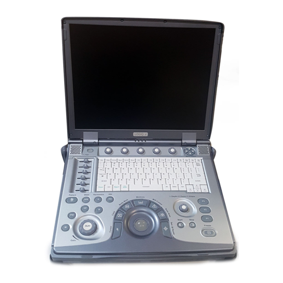
GE LOGIQ e Quick Manual
Hide thumbs
Also See for LOGIQ e:
- Technical publication (127 pages) ,
- Basic service manual (427 pages)
Advertisement
Table of Contents
- 1 System Power
- 2 Starting an Exam
- 3 B/M Mode Image Optimize
- 4 B Mode Control Panel Controls
- 5 B/M Mode Scanning Hints
- 6 Scanning Hints
- 7 Basic Measurements
- 8 Using Probes
- 9 Probe Features
- 10 Specifications
- 11 Probe Cleaning and Disinfection Instructions
- 12 Probe Safety
- 13 Image Management
- 14 Configuring Connectivity
- 15 Using CINE
- Download this manual
Advertisement
Table of Contents

Related Manuals for GE LOGIQ e


Summary of Contents for GE LOGIQ e
- Page 1 RikshospitaletHF Hurtigveiledning Ultralydskanner Figure 1. Steg 1 Steg 1 SKRU PÅ MASKINEN. Kom igang...
- Page 2 LOGIQ e Quick Guide LOGIQ e Knotologi 1. TGC. Juster venstre/høyre for justernig TGC. 2. Ny pasient. Trykk for aktivering. 3. Additional Feature Keys: Steer, Harmonics, PDI. 4. Mode/Gain/Auto Keys: M Mode, Pulsed Wave Doppler (PW) Modes, Color Flow (CF) Mode and B Mode.
- Page 3 LOGIQ e Quick Guide Direction 5130174-100 Rev. 2 LOGIQ e Keys SoftMenu Key Tour Function Keys - Programmable Keys Choices for program Keys In general, there are two types of softMenu keys: • F1 = Help (Enter Online Help / User Manual) •...
- Page 4 LOGIQ e Quick Guide Direction 5130174-100 Rev. 2 LOGIQ e Monitor Display Tour 1. Institution/Hospital Name, Date, Time, Operator 7. Cine Gauge. 16. Body Pattern. Identification, system status (real-time of 8. Measurement Summary Window. 17. Depth Scale. frozen). 9. Image.
-
Page 5: System Power
LED is orange. Colors: Green and 220-240 VAC 220-240 VAC 2.5A 2.5A orange. (Europe) (Israel) 4. The fourth LED does not work on the LOGIQ e. 100-120 VAC 220-240 VAC 2.5A 2.5A (Japan) (Australia) Table 1: Example Plug and Outlet Configurations Figure 8. - Page 6 LOGIQ e Quick Guide Direction 5130174-100 Rev. 2 Power Off Full Maintenance Reboot Click OK to continue the process. The auto full maintenance reboot process takes about 2 minutes, To power down the system: You can select Full Maintenance Reboot to fully and is completed when the system is shut down restart the system.
-
Page 7: Starting An Exam
LOGIQ e Quick Guide Direction 5130174-100 Rev. 2 Starting an Exam New Patient Probe Selection Function Selection Window [2] New Patient is used to clear the patient entry To start a new patient’s exam, Select a probe from the Touch Panel (the system screen to input a new patient’s data into the... -
Page 8: B/M Mode Image Optimize
LOGIQ e Quick Guide Direction 5130174-100 Rev. 2 B/M Mode Image Optimize Frame Average B Mode Control Panel Controls Temporal filter that averages frames together. This Power Output Auto Optimize has the effect of presenting a smoother, softer image. Optimizes image quality and allows user to reduce Automatic Tissue Optimization optimizes the image beam intensity. -
Page 9: B/M Mode Scanning Hints
LOGIQ e Quick Guide Direction 5130174-100 Rev. 2 B/M Mode Image Optimize (continued) B/M Mode Scanning Hints Maps. There is an inter-dependency between gray Edge Enhance. Better delineates the amount of maps, gain, and dynamic range. If you change a border crispness. -
Page 10: Scanning Hints
LOGIQ e Quick Guide Direction 5130174-100 Rev. 2 Color Flow/Doppler Image Optimize Sample Volume Gate Length 6. Increase Frame Average. 7. Increase the Packet Size. Sizes the sample volume gate. 8. Reduce the ROI to the smallest reasonable Baseline size. - Page 11 LOGIQ e Quick Guide Direction 5130174-100 Rev. 2 Color Flow/Doppler Image Optimize (continued) CFM Menu with Primary and Secondary Controls PWM Menu with Primary and Secondary Controls Color Flow/Doppler Image Optimize...
-
Page 12: Basic Measurements
LOGIQ e Quick Guide Direction 5130174-100 Rev. 2 Basic Measurements NOTE: The following instructions assume that you Circumference/Area (Ellipse) Measurement Circumference/Area (Trace) Measurement first scan the patient and then press Freeze. 1. Press Measure once; an active caliper 1. Press Measure twice; a trace caliper displays. - Page 13 LOGIQ e Quick Guide Direction 5130174-100 Rev. 2 Volume Velocity Measurement Worksheets 1. To make a volume calculation, do one of the 1. Press Measure; an active caliper with a vertical Measurement/Calculation worksheets are available following: dotted line displays. to display and edit measurements and calculations.
-
Page 14: Using Probes
2. Carefully remove the probe and unwrap the 1. Ensure the LOGIQ e is in freeze mode. If probe cable. necessary, press the Freeze key. Fault conditions can result in electric shock hazard. - Page 15 LOGIQ e Quick Guide Direction 5130174-100 Rev. 2 Probe Application Table 2: Probe Indications for Use Probe Application 4C-RS E8C-RS 8L-RS 8C-RS i12L-RS 3S-RS 12L-RS Abdomen Small Parts Obstetrics Gynecology Pediatrics Neonatal Urology Cardiac Endocavity Transcranial Intraoperative Vascular Biopsy Main Application...
-
Page 16: Probe Features
LOGIQ e Quick Guide Direction 5130174-100 Rev. 2 Probe Features Table 3: Probe Features Probe Feature 4C-RS E8C-RS 8L-RS 8C-RS i12L-RS 3S-RS 12L-RS LOGIQ View Virtual Convex Easy 3D M Color Flow Tru Access Non-Imaging CW Compounding Specifications Table 4: System Probe Definitions... -
Page 17: Probe Cleaning And Disinfection Instructions
• DO NOT kink, tightly coil, or apply excessive force on the probe cable. Insulation failure may result. • Electrical leakage checks should be performed on a routine basis by GE Service or qualified hospital personnel. Refer to the service manual for leakage check procedures. - Page 18 You MUST disconnect the probe from the LOGIQ e 3. After removing from the germicide, rinse the prior to cleaning/ disinfecting the probe. Failure to probe following the germicide manufacturer's do so could damage the system.
-
Page 19: Image Management
From the New Patient menu, open Active Images. Connectivity View active exam images. 1. Trackball to the patient’s name to highlight the Connectivity on the LOGIQ e is based on the name, (or perform a search to locate the Deleting an Image Dataflow concept. -
Page 20: Configuring Connectivity
LOGIQ e Quick Guide Direction 5130174-100 Rev. 2 Configuring Connectivity Login as Administrator. Press the right Utility tab. Device Services (better known as Destinations) Select the Connectivity tab. Configure the menus from left to right, starting with TCP/IP first. 1. Press Add to create a new device. - Page 21 LOGIQ e Quick Guide Direction 5130174-100 Rev. 2 Services (cont’d) Buttons You can assign print buttons (P1-P3) to a device or e. In the Services drop-down menu, select to a dataflow. "Dicom Performed Procedure" and press 1. Select “Dicom Image Storage”, add to Printflow [Add].
- Page 22 LOGIQ e Quick Guide Direction 5130174-100 Rev. 2 Dataflow DICOM Status Creates a Dataflow, (‘WL-LA-DServ -- Worklist, To check the status of all DICOM jobs or redirect Local Archive, DICOM* Server, for example). DICOM jobs, press F4 to open the spooler.
-
Page 23: Using Cine
LOGIQ e Quick Guide Direction 5130174-100 Rev. 2 Using CINE Start Frame/End Frame Adjusting the CINE Loop Playback Speed Press the Start Frame Softkey to move to the Adjust the Loop Speed Softkey to increase/ Activating CINE beginning of the CINE Loop. Adjust the Start decrease the CINE Loop playback speed. - Page 24 LOGIQ e Quick Guide Direction 5130174-100 Rev. 2 Easy 3D Acquiring a 3D Scan Manipulating the 3D Scan Performing a Surface Render 1. Optimize the B-Mode image. Ensure even gel Imagine you are able to manipulate the 3D volume From the 3D Touch Panel, press 3D, then press coverage.
- Page 25 Global Service User Interface 2. Now user can enter Global Service User interface. Choose Diagnostics, and then we enter LOGIQ e Diagnostics menu. How to enter the global service interface 1. Press the Utility tab, select Service tab in Utility window, netscape will show GEMS Service Home Page.
Need help?
Do you have a question about the LOGIQ e and is the answer not in the manual?
Questions and answers
ACCESS SYSTEM AFTER F11 THE KEYBOARD DO NOT RESPONDS
If pressing F11 on the GE LOGIQ e does not produce the expected result, follow these troubleshooting steps:
1. Verify Function Assignment: F6–F12 keys are user-definable. Ensure F11 is assigned to a function by checking the key configuration under the [Utility] menu.
2. Check Utility Settings: Press [Utility] to access system configuration. Navigate to the function assignment section and confirm F11 is set correctly.
3. Restart the System: Perform a full maintenance reboot. Press the Power On/Off switch, and using the Trackball and Select key, choose Full Maintenance Reboot.
4. Check for System Lag: If the system is slow, it may affect key response. A full maintenance reboot may improve performance.
5. Verify System Date/Time: If access issues occur, go to Utility -> System -> General -> Date/Time, update to the correct date, and try again.
6. Reassign the Key: If F11 is not responding, try reassigning it to a different function using the Utility menu.
If these steps do not resolve the issue, further service intervention may be required.
This answer is automatically generated
how to get password