GE Logiq 500 User Manual
Hide thumbs
Also See for Logiq 500:
- Advanced reference manual (474 pages) ,
- Service manual (407 pages) ,
- Unpacking instructions manual (14 pages)

Subscribe to Our Youtube Channel
Related Manuals for GE Logiq 500


Summary of Contents for GE Logiq 500
- Page 1 GE Medical Systems Technical Publications 2233658-100 Revision 0 LOGIQ t 500 Basic Users Manual Copyright 1999 By General Electric Co. Operating Documentation...
- Page 2 500 MD MR3 Plus. It applies to all versions of 4.2 software for the LOGIQ 500. GE Medical Systems GE Medical Systems: Telex 3797371 P.O. Box 414, Milwaukee, Wisconsin 53201 U.S.A. (Asia, Pacific, Latin America, North America) GE Medical Systems Europe: T el: +49 (0) 212 28 02 208 Beethovenstraße 239, Postfach 11 05 60, D-42655 Solingen...
- Page 3 GPC (GE Medical Systems Global Product Configuration). If you need to know the latest revision, contact your distributor, local GE Sales Representative or in the USA call the GE Ultrasound Clinical Answer Center at 1-800-682-5327 or 414-524-5698.
-
Page 4: Logiq 500 Basic Users Manual 2233658–100 Rev
Revision History This page left blank intentionally. Revision History B LOGIQ 500 Basic Users Manual 2233658–100 Rev. 0... - Page 5 Directive. The location of the CE marking is shown on 2–23 of this manual. European registered place of business: GE Medical Systems Europe Quality Assurance Manager BP 34 F 78533 BUC CEDEX France Tel: +33 (0)1 30 70 40 40...
- Page 6 Regulatory Requirements NOTE: This equipment generates, uses and can radiate radio frequency energy. The equipment may cause radio frequency interference to other medical and non-medical devices and radio communications. To provide reasonable protection against such interference, this product complies with emissions limits for a Group 1, Class A Medical Devices Directive as stated in EN 60601–1–2.
-
Page 7: Table Of Contents
......... . 1–6 Contacting GE Medical Systems—Ultrasound .... - Page 8 Table of Contents Chapter 3—Preparing the System for Use Site Requirements ........3–2 Introduction .
- Page 9 Table of Contents Chapter 4—Preparing for an Exam Beginning an Exam ........4–2 Introduction .
- Page 10 Table of Contents 3D-Surface Mode (Option) ....... . . 5–73 Overview .
- Page 11 Table of Contents Chapter 7—General Measurements and Calculations Introduction ..........7–2 Overview .
- Page 12 Table of Contents Chapter 9—OB/GYN (Basic OB software option) Exam Preparation ......... 9–2 Overview .
- Page 13 Table of Contents Chapter 10—Cardiology (software option) Introduction ..........10–3 Overview .
- Page 14 Table of Contents Chapter 11—Vascular (software option) Exam Preparation ......... 11–2 Introduction .
- Page 15 Table of Contents Chapter 14—Customizing Your System Time Adjustment ......... 14–3 Overview .
- Page 16 Table of Contents Preset Program ......... . . 14–64 Overview .
- Page 17 Table of Contents Chapter 15—Probes and Biopsy Probe Overview ......... . . 15–2 Labeling .
- Page 18 Table of Contents Warranties ..........16–7 Scope and Duration of Warranties .
-
Page 19: System Overview
System Overview System Overview Attention This manual contains enough information to operate the system safely. Advanced equipment training may be provided by a factory trained Applications Specialist for the agreed upon time period. Read and understand all instructions in this manual before attempting to use the LOGIQ 500 system. -
Page 20: Physical Principle Used
System Overview Physical Principle Used The transmission and reception of mechanical high frequency waves through a transducer associated with a computer that creates the image in a digital memory, are used for the creation of medical ultrasound images. The spreading of mechanical ultrasound waves produces echoes when body changes density. -
Page 21: General Indications For Use
System Overview General Indications for Use The LOGIQ 500 is a general purpose ultrasound imaging system intended for use in the dynamic evaluation of soft tissue and vascular diseases in the following areas: Head Neck Chest Abdomen Pelvis Male reproductive organs Female reproductive organs Limbs/Extremities Pregnant uterus... -
Page 22: Contraindications
System Overview Contraindications The system is NOT intended for use in the following areas: Ophthalmic use (or any use causing the acoustic beam to pass through the eye). Pulsed Wave Doppler, Continuous Wave Doppler, Color Flow Doppler, and Color M-Mode are not intended for routine fetal examination or screening nor are they intended for fetal examination in a low-risk population. -
Page 23: Who To Contact
Who To Contact Who To Contact Contacting GE Medical Systems—Ultrasound For additional information or assistance, please contact your local distributor or the appropriate support resource listed below: GE Medical Systems TEL: (1) 800–437–1171 Ultrasound Service Engineering FAX: (1) 414–647–4090 4855 W. Electric Avenue... - Page 24 Who To Contact Contacting GE Medical Systems—Ultrasound (cont’d) ARGENTINA GEME S.A TEL: (1) 639–1619 Miranda 5237 FAX: (1) 567–2678 Buenos Aires – 1407 AUSTRIA GE GesmbH Medical Systems Austria TEL: 0660 8459 toll free Prinz Eugen Strasse 8/8 FAX: +43 1 505 38 74 A–1040 WIEN...
- Page 25 Who To Contact Contacting GE Medical Systems—Ultrasound (cont’d) MEXICO GE Sistemas Médicos de Mexico S.A. de C.V Rio Lerma #302, 1º y 2º Pisos TEL: (5) 228–9600 Colonia Cuauhtémoc FAX: (5) 211–4631 06500–México, D.F. NETHERLANDS GE Medical Systems Nederland B.V.
-
Page 26: Manufacturer
Who To Contact Contacting GE Medical Systems—Ultrasound (cont’d) TURKEY GE Medical Systems Turkiye A.S. TEL: +90 212 75 5552 Mevluk Pehliran Sodak FAX: +90 212 211 2571 Yilmaz Han, No 24 Kat 1 Gayretteppe ISTANBUL UNITED KINGDOM IGE Medical Systems... -
Page 27: How This Book Is Organized
How This Book is Organized How This Book is Organized Manual Content The LOGIQ 500 Basic User Manual is organized to provide the information needed to start scanning right away. Detailed information is also provided for more time-intensive studies. Getting started. These sections give an overview of the system to help the operator start scanning as soon as possible. - Page 28 How This Book is Organized Manual Content (cont’d) Measurements and Reports. Shows how to do general and exam category specific measurements and calculations. General Measurements and Calculations . Emphasis on basic measurements for each mode. Exam Categories. Abdomen and Small Parts. OB/GYN .
-
Page 29: Manual Format
How This Book is Organized Manual Format Information has been arranged and provided to help find information easily and quickly. Finding information Tables of Contents Locate topics in the main table of contents. Tabs Chapter tabs are provided. Headers/Footers The section name and page number appear on the outer corners of every page. -
Page 30: Safety Precautions
Safety Precautions Safety Precautions Precaution Levels Icon Description Various levels of safety precautions may be found on the equipment and different levels of concern are identified by one of the following flag words which precede the precautionary statement. Indicates that a specific hazard is known to exist which through DANGER inappropriate conditions or actions will cause: Severe or fatal personal injury... -
Page 31: Hazard Symbols
Safety Precautions Hazard Symbols Icon Description Potential hazards are indicated by the following icons: Icon Potential Hazard Usage Source Biological Patient/user infection due Cleaning and care ISO 7000 to contaminated instructions No. 0659 Hazard equipment. Sheath and glove guidelines Electrical micro-shock to Probes Electrical patient, e.g., ventricular... -
Page 32: Patient Safety
The equipment user must become thoroughly familiar with the equipment operation in order to optimize its performance and recognize possible malfunctions. Applications training is available through the local GE representative. Added confidence in the equipment operation can be gained by establishing a quality assurance program. - Page 33 Training It is recommended that all users receive proper training in applications before performing them in a clinical setting. Please contact the local GE representative for training assistance. ALARA training is provided by GE Application Specialists. LOGIQ 500 Basic Users Manual 2–5...
-
Page 34: Equipment And Personnel Safety
Safety Precautions Equipment and Personnel Safety Related Hazards This equipment contains dangerous voltages that are capable WARNING of serious injury or death. There are no user serviceable components inside the console. Refer all servicing to qualified service personnel only. The concerns listed below can seriously affect the safety of DANGER equipment and personnel during a diagnostic ultrasound examination. - Page 35 Safety Precautions Related Hazards (cont’d) For patient and personnel safety, beware of biological hazards Biological while performing invasive procedures. To avoid the risk of Hazard disease transmission: Use protective barriers (gloves and probe sheaths) whenever possible. Follow sterile procedures when appropriate.
-
Page 36: Device Labels
Safety Precautions Device Labels Label Icon Description The following table describes the purpose and location of safety labels and other important information provided on the equipment. Label/Icon Purpose/Meaning Location Identification and Rating Manufacturer’s name and address Rear of console near power Plate inlet Date of manufacture... - Page 37 Safety Precautions Label Icon Description (cont’d) Label/Icon Purpose/Meaning Location “ATTENTION – Consult accompanying Various documents” is intended to alert the user to refer to the operator manual or other instructions when complete information cannot be provided on the label. “CAUTION – Dangerous voltage” (the lightning flash with arrowhead) is used to indicate electric shock hazards.
- Page 38 Safety Precautions Classifications Type of protection against electric shock Class I Equipment (*1) Degree of protection against electric shock Type BF Equipment (*2) (Except ECG) Type CF Equipment (*3) (ECG Only) Ordinary Equipment Continuous Operation *1. Class I EQUIPMENT EQUIPMENT in which protection against electric shock does not rely on BASIC INSULATION only, but includes an earth ground.
- Page 39 Safety Precautions Classifications (cont’d) *4. EMC (Electromagnetic Compatibility) 4.1 EMC Performance All types of electronic equipment may characteristically cause electromagnetic interference with other equipment, either transmitted through air or connecting cables. The term EMC (Electromagnetic Compatibility) indicates the capability of equipment to curb electromagnetic influence from other equipment and at the same time not affect other equipment with similar electromagnetic radiation from itself.
- Page 40 Safety Precautions Classifications (cont’d) 4.2 Notice upon Installation of Product 1. Use either power supply cords provided by GE Medical Systems or ones designated by GE Medical Systems. Products equipped with a power source plug should be plugged into the fixed power socket which has the protective grounding conductor.
- Page 41 Safety Precautions Classifications (cont’d) 4.3 General Notice (cont’d) 2. Notice against User Modification The user should never modify this product. User modifications may cause degradation in EMC performance. Modification of the product includes changes in: a. Cables (length, material, wiring, etc.) b.
- Page 42 Safety Precautions Classifications (cont’d) *5. Patient Environmental Devices Î Î Î Î Î Î Peripherals Î Î Î Î Î Î (1) VCR Î Î Î Î Î Î (2) B/W Video Printer Î Î Î Î Î Î (3) Color Video Î...
- Page 43 5.2 Unapproved Devices The user takes All Responsibility for connecting unapproved CAUTION devices. If devices are connected without the approval of GE, the warranty will be INVALID. Any device connected to the LOGIQ 500 must conform to one or more of the requirements listed below: 1.
-
Page 44: Acoustic Output
Safety Precautions Acoustic Output Controls Affecting Output The potential for producing mechanical or thermal bioeffects is influenced by the controls listed below (refer to 2–17 ). Direct. The Acoustic Output control has the most significant effect on Acoustic Output. Indirect. Indirect effects may occur when adjusting the controls listed on 2–17 . - Page 45 Safety Precautions Best practices while scanning (cont’d) Controls Mode Control Affect Default Setting Acoustic Output Direct. The middle setting is a factory preset Significant determined to be a reasonable setting for all exams. Use presets to set the output preferred by scan mode and exam combination.
-
Page 46: Warning Label Locations
A temporary label is placed on the monitor face to warn not to move the monitor support arm without the monitor attached. This label is removed after installation of the monitor. LOGIQ 500 MD Push Open Figure 2–2. Temporary Warning Label and Location 2–18... - Page 47 Safety Precautions Monitor Labels (cont’d) Two caution labels are found on the back of the monitor. One warns to only move the console with the monitor in its lowest position; the second warns not to push the console from the side.
- Page 48 Safety Precautions Monitor Labels (cont’d) One caution label is found on the top of the monitor. Figure 2–4. Top of Monitor Caution and Location 2–20 LOGIQ 500 Basic Users Manual 2233658–100 Rev. 0...
- Page 49 Safety Precautions Console Labels Labels found on the back and side of the console will either be translated to the twelve languages or be specific to the region. Defibrillator Caution LOGIQ Figure 2–5. Defibrillator Label Location LOGIQ 500 Basic Users Manual 2–21 2233658–100 Rev.
- Page 50 Safety Precautions Ground Point Ï Ï Ï Ï Ï Ï Ï Ï Ï Ï Ï Ï Ï Ï Ï Ï Ï Ï Ï Ï Figure 2–6. Signal Ground Point Location and Label This is only for “FUNCTIONAL GROUNDING”, NOT CAUTION “PROTECTIVE EARTH”.
- Page 51 Safety Precautions Regulatory Labels (European Systems) Figure 2–7. Regulatory Label Location (European) LOGIQ 500 Basic Users Manual 2–23 2233658–100 Rev. 0...
- Page 52 Safety Precautions Regulatory Labels (American Systems) Figure 2–8. Regulatory Label Location (Americas) 2–24 LOGIQ 500 Basic Users Manual 2233658–100 Rev. 0...
-
Page 53: Site Requirements
Site Requirements Site Requirements Introduction Only qualified physicians or sonographers should perform ultrasound scanning on human subjects for medical diagnostic reasons. Request training, if needed. Do not attempt to install the system alone. General Electric, Affiliate, or Distributor Field Engineers and Application Specialists will install and setup the system. -
Page 54: Before The System Arrives
Site Requirements Before the system arrives NOTICE This medical equipment is approved, in terms of the prevention of radio wave interference, to be used in hospitals, clinics and other institutions which are environmentally qualified. The use of this equipment in an inappropriate environment may cause some electronic interference to radios and televisions around the equipment. -
Page 55: Environmental Requirements
Site Requirements Environmental Requirements The system should be operated, stored, or transported within the parameters outlined below. Either its operational environment must be constantly maintained or the unit must be turned off. Operational Storage Transport (<16 hrs.) 10 _ - 40 _ C –10 _ - 60 _ C –40 _ - 60 _ C Temperature... -
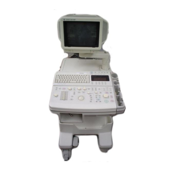
Page 56: Console Overview
Console Overview Console Overview Console graphics The following are illustrations of the console: Optional Probe Cable Holder (wire holder standard for Americas’ systems) Probe and Gel Bottle Holder (Removable for Cleaning) Optional Cable Clipper for Probe Cable Figure 3–1. LOGIQ 500 System (right and left side views) LOGIQ 500 Basic Users Manual... - Page 57 Console Overview Console graphics (cont’d) Ï Ï Ï Ï Ï Ï Ï Ï Task Light Switch Task Light Optional B/W Video Page Printer Air Filter (front and back of system) Power Supply Air Filter Optional Probe Cable Holder (wire holder standard for Americas’ systems) VCR Microphone Release Button—to raise and lower video monitor Optional Physiological Input Panel...
- Page 58 Storage areas Several convenient storage areas are provided within the console as shown by the shaded areas in Figure 3–3. Use them to store gel, options, probe cables, accessories, etc. LOGIQ 500 LOGIQ 1 Storage Figure 3–3. Storage Areas LOGIQ 500 Basic Users Manual 3–7...
-
Page 59: Peripheral/Accessory Connection
Console Overview Peripheral/Accessory Connection Peripheral/Accessory Connector Panel LOGIQ 500 peripherals and accessories can be properly connected using the rear connector panel located behind the rear door. Only the B/W Page Printer (UP-890) can be connected to the front accessory panel. Located on the rear panel are video input and output, audio input and output, camera expose, foot switch, power and control connections for VCR, printer, MIC and service tools. - Page 60 Console Overview Peripheral/Accessory Connector Panel (cont’d) Ï Ï Ï Ï Ï Ï Ï Ï Ï Ï Ï Ï Ï Ï Ï Ï 100V 5.0A Max. Including front printer panel 120V 4.1A Max. Including front printer panel 220–240V 2.0A Max. Including front printer panel Old Rear Panel New Rear Panel Figure 3–5.
- Page 61 Record The Foot Switch connection is located at the back of the Foot Switch console on the left-hand side of the back panel. LOGIQ 500 Ï Ï Ï Ï Ï Ï Ï Ï Ï Ï Ï Ï Ï Ï Ï Ï...
-
Page 62: System Positioning/Transporting
System Positioning/Transporting System Positioning/Transporting Moving the System When moving or transporting the system, follow the precautions below to ensure the maximum safety for personnel, the system, and other equipment. Before moving the system: 1. Turn the system power switch off. 2. - Page 63 System Positioning/Transporting Moving the System (cont’d) Ï Ï Ï Ï Ï Ï Ï Ï Ï Ï Ï Ï Ï Ï Ï Handle Storage Area Behind Door Figure 3–7. Location of Storage Area 6. Connect all probes to be used while off site. Ensure that probe cables are out of the way from the wheels and not protruding beyond the console.
- Page 64 System Positioning/Transporting Moving the System (cont’d) When moving the system: 1. Always use the rear handle grips to move the system. 2. Take extra care when moving the system long distances and on inclines. Ask for help if necessary. Avoid ramps that are steeper than ten degrees to avoid tipping over the system.
-
Page 65: Transporting The System
System Positioning/Transporting Transporting the System Use extra care when transporting the system using vehicles. In addition to the instructions used when moving the system (refer to 3–11 ), do the following: 1. Only use vehicles that are designed for transport of the LOGIQ 500 system. -
Page 66: Wheels
System Positioning/Transporting Wheels Examine the wheels frequently for any obvious defects that could cause them to break or bind. Front wheels The front wheels swivel, pivot, and lock. Back wheels The back wheels swivel and pivot but do not lock. NOTE: For the USA version console, the back wheels do not pivot. -
Page 67: Powering On The System
Powering On the System Powering On the System Connecting and Using the System To connect the system to the electrical supply: 1. Ensure that the wall outlet is of the appropriate type. 2. Ensure that the power switch is turned off. 3. - Page 68 Powering On the System Acclimation Time After being transported, the unit requires one hour for each 2.5 _ increment its temperature is below 10 _ C or above 40 _ C. hours –5 –10 –15 –20 –25 –30 –35 –40 –4 –13 –22...
- Page 69 Powering On the System Power Up Sequence The monitor and console power indicator light up. The system is initialized. During this time: Two beeps sound during the sequence. All lighted buttons on the keyboard light. System diagnostics run. Its status is reflected on the monitor by the graphics in Figure 3–10 .
- Page 70 Powering On the System Power Up Sequence (cont’d) NOTE: If errors occur, an error message appears at the bottom of the screen. See User Maintenance, Troubleshooting for more information. If problems occur, freeze the image and take a picture Hints for reference.
- Page 71 Powering On the System Password Protection (cont’d) USER ID PASSWORD: Version X.XX Figure 3–11. System Startup Screen with Password Ask on If the correct User ID/Password is entered, the system continues with the power up sequence. If an incorrect User ID/Password is entered, the system allows four additional attempts.
- Page 72 Powering On the System Power Off When switching off the system: Move the ON, OFF/STAND-BY switch to the OFF position. The message “WARNING: NOW STARTING THE POWER OFF PROCESS” appears at the bottom of the display. The LOGIQ 500 takes a few seconds to save current scan parameter data in the temporary files to the hard drive before turning the power off.
- Page 73 Powering On the System Circuit breaker The Circuit Breaker is located on the back of the console, at the bottom of the system. On supplies main power to all internal systems. Off removes main power from all internal systems. The circuit breaker automatically shuts off power to the system in case of a power overload.
- Page 74 Powering On the System Circuit breaker (cont’d) Ï Ï Ï Ï Ï Ï Ï Ï Ï Ï Ï Ï Circuit Breaker Figure 3–12. Location of Circuit Breaker LOGIQ 500 Basic Users Manual 3–23 2233658–100 Rev. 0...
-
Page 75: Adjusting The Display Monitor
Adjusting the Monitor Adjusting the Display Monitor Rotate, tilt, raise and lower the monitor The monitor position can be adjusted for easy viewing. The monitor can be rotated around it’s central pivot point. The monitor can be tilted for the optimum viewing angle. The monitor arm can swing forward or backwards. -
Page 76: Brightness And Contrast
Adjusting the Monitor Brightness and Contrast Adjusting the monitor’s contrast and brightness is one of the most important factors for proper image quality. If these controls are set incorrectly, the Gain, TGC, Dynamic Range and even Acoustic Output may have to be changed more often than necessary to compensate. - Page 77 Adjusting the Monitor Brightness and Contrast (cont’d) 2. Enter menu number “11” (Monitor Adjustment) in the Utility Menu and press Return. The Monitor Adjustment Menu appears as shown in Figure 3–15. Figure 3–15. Monitor Adjustment Menu 3. Enter the number of a gray scale map for adjustment according to the brightness of the exam room and the exam category and press Return.
- Page 78 Adjusting the Monitor Brightness and Contrast (cont’d) The adjustment maps’ gray scale bar appears on the monitor as shown in Figure 3–16. Gray Scale Bar Task Light Button Brightness Task Light Contrast Microphone Figure 3–16. Brightness and Contrast 4. Access the Brightness/Contrast controls by pushing on the top center of the control panel door, located under the display screen.
-
Page 79: Speakers
Adjusting the Monitor Brightness and Contrast (cont’d) Generally speaking, do not change the controls once they have been set. Once set, the display then becomes the reference for the hard copy device(s). NOTE: After readjusting the monitor’s Contrast and Brightness, readjust all preset and peripheral settings. -
Page 80: Probes
Probes Probes Introduction Only use approved probes. All imaging probes can be plugged into any of the three probe ports. For more Refer to the Probes chapter. information Connecting the Probe Probes can be connected at any time, regardless of whether the console is powered on or off. - Page 81 Probes Connecting the Probe (cont’d) Figure 3–18. Probe Connector Panel 6. Turn the connector locking handle clockwise to secure the probe connector. 7. Carefully position the probe cord so it is free to move and is not resting on the floor. lock unlock Figure 3–19.
-
Page 82: Cable Handling
Probes Cable Handling Take the following precautions with probe cables: Keep free from wheels Do not bend the cable acutely Avoid crossing cables between probes. Activating the Probe To activate the probe, press the Probe Select key that corresponds to the probe port to which the desired probe is connected. -
Page 83: Deactivating The Probe
Probes Probe Name Menu If the Display Probe Name preset in the Setup/System Parameters page one is ON, by pressing a half bright or brightly lit key causes the probe names for each port to be displayed in the soft menu. The desired probe can then be selected from the soft menu or by pressing the Probe Select keys. -
Page 84: Disconnecting The Probe
Probes Disconnecting the Probe Probes can be disconnected at any time. However, the probe should not be selected as the active probe. Move the probe locking handle counterclockwise. Pull the probe and connector straight out of the probe port. Carefully slide the probe and connector away from the probe port and around the right side of the keyboard. -
Page 85: Operator Controls
Operator Controls Operator Controls Control Panel Map Controls are grouped together by function for ease of use. See the callouts for this illustration on the following page. " " Figure 3–22. Control Panel 3–34 LOGIQ 500 Basic Users Manual 2233658–100 Rev. 0... -
Page 86: Key Illumination
Operator Controls Control Panel Map (cont’d) 1. Alphanumeric Keyboard (see 3–34 ). 2. Patient Information (see 4–3 ). 3. Probe Selection (see 3–29 ). 4. Soft Menu (see 3–37 ). 5. Doppler CFM (see 5–28 and 5–50 ). 6. User Define (see 14–97 ). 7. -
Page 87: Keyboard
Operator Controls Keyboard The standard alphanumeric keyboard has some special functions. The Cursor Home key brings the alphanumeric cursor to the very upper left corner of the available field. Control is used in conjunction with other keys to activate special keyboard functions. -
Page 88: Soft Menu Control Panel
Operator Controls Soft Menu Control Panel Additional functionality, not available as a control or key on the front panel, can be found via the Soft Menus. Different soft menus appear depending on the mode, special function or calculation package selected. The Soft Menu consists of Top Menu Select keys and Sub-Menu Select rocker switches. - Page 89 Operator Controls Top Menu Organization The Top Menu Select key cycles through the top level menu page selections. The far left side top menu is the default selection and its sub-menus are automatically displayed. The top menu groups are divided into two pages. The first top menu page displays: Mode Default Preset...
- Page 90 Operator Controls Top Menu Organization (cont’d) The four top menu select keys select and highlight the corresponding top menu and display its associated sub-menus. Four keys on the front panel automatically disable all top menus and display specific sub-menu selections. Body Pattern displays the available graphic selections in the sub-menu area.
-
Page 91: Mode, Display And Record
Operator Controls Mode, Display and Record This group of controls provides various functions relating to the display mode, display orientation, image recording/saving, freeze, gain and cine scroll. The Mode Controls select the desired display mode or combinations of display modes. During dual display modes the L and R keys activate the Left or Right displayed image. - Page 92 Operator Controls Mode, Display and Record (cont’d) Record 1 and Record 2 are used to activate/print the designated recording device (i.e. video page printer, multi-image camera, image archive option). The Freeze key is used to stop the acquisition of ultrasound data and freeze the image in system memory.
-
Page 93: Measurement And Annotation
Operator Controls Measurement and Annotation This group of controls performs various functions related to making measurements, annotating and adjusting the image information. The Comment key enables the image text editor and displays the annotation library soft menu. For more details, refer to 6–16 . - Page 94 Operator Controls Measurement and Annotation (cont’d) The Ellipse rocker switch is used to activate the ellipse measurement function after the first distance measurement has been set. It also toggles which cursor is the movable cursor during the ellipse adjustment. The Set key is used for various functions, but is generally used to fix or finish an operation (i.e.
-
Page 95: Vcr Controls
Operator Controls VCR Controls These controls are used in conjunction with the approved optional video cassette recorder. Press the External Video key to allow for the display of an external video signal (i.e. from a VCR) on the system monitor. Pressing Play automatically selects external video. -
Page 96: Beginning An Exam
Beginning an Exam Beginning an Exam Introduction Begin an exam by entering new patient information. The operator should enter as much information as possible, such as: Exam category Patient name Patient ID Comments Exam Information The patient’s name and ID number is retained with each patient’s image and transferred with each image during archiving or hard copy printing. -
Page 97: Beginning A New Patient
Beginning an Exam Beginning a New Patient The New Patient key should be pressed at the beginning of each patient study. Pressing this key automatically erases all patient data, annotations, measurements, calculations and summary report pages. A preset parameter can be set to prompt the user if they wish to erase all patient data or not. - Page 98 Beginning an Exam Beginning a New Patient (cont’d) The first Data Entry field is presented in reversed display. Trackball to the exam category selection. Select from 7 examination categories: Radiology/Abdominal, Obstetrics, Gynecology, Cardiology, Vascular, Urology and Small Parts. Input the appropriate number. The patient information input menu changes.
-
Page 99: Id/Name
Beginning an Exam Beginning a New Patient (cont’d) NOTE: If patient information needs to be edited or the exam category changed, use the ID Name key. Pressing ID Name allows for modification of the Patient Entry Menus without erasing accumulated patient images, measurements, annotations, calculations and summary reports. - Page 100 Beginning an Exam Helpful hints If power is lost during the ID/Name function, any data that was Hints added or modified will not be saved. Patient information/setup is saved to the system hard drive at power off only if the System Parameters (page 1) preset “Power On Status”...
-
Page 101: Exam Application Preset Selection
Exam Applic. Preset Selection Exam Application Preset Selection Introduction Select the exam category application preset, that best describes the desired study to be performed, from the factory default preset selections displayed on the Soft Menu. A typical example for OB is shown in Figure 4–2. General Fetal Heart... - Page 102 Exam Applic. Preset Selection This page left blank intentionally. 4–8 LOGIQ 500 Basic Users Manual 2233658–100 Rev. 0...
-
Page 103: B-Mode
B–Mode B-Mode Introduction The LOGIQ 500 offers a wide variety of display formats. Each format shows the operator valuable information relating to patient data and system scan parameters. B-Mode, also referred to as 2-D Mode, displays a two dimensional gray scale image of the structures within the probe’s field of view. -
Page 104: Reading The B-Mode Display
B–Mode Reading the B-Mode Display Figure 5–1 shows the basic B-Mode display information. Ç LMP=xx/xx/xx Ç Ç Ç Ç Ç Ç Ç Ç Ç Ç Ç Ç Figure 5–1. B-Mode Display Format LOGIQ 500 Basic Users Manual 5–3 2233658–100 Rev. 0... - Page 105 Probe name or designation of the active probe. Scan Orientation GE or the marker is used for scan orientation. This should coincide with the probe orientation marking on the probe body. This marker can be turned off in Set GE or Up/Custom Display page 10.
- Page 106 B–Mode Reading the B-Mode Display (cont’d) Graphic Display Description, Format, Values B Gray Scale Map The B gray scale map number is displayed above the gray scale bar on only B Number Mode. The B gray scale map number disappears when B-Color is active. When ATO map is active, the asterisk (*) is displayed on the right side of the gray scale map number.
- Page 107 B–Mode Reading the B-Mode Display (cont’d) Graphic Display Description, Format, Values Measurements Lines of image measurement data are displayed in this area. The format and value depends on the type of measurement. The bottom line fills first and scrolls up as additional information is obtained. Operator Messages System generated messages are displayed on this line (i.e.
- Page 108 B–Mode Acoustic Output Display (cont’d) Acoustic Output Index Display Function Other Operation Mode B Only Display MI Setup/Custom (Mechanical Display page 10 Index) Value Selection Display TIS (Soft Display TIB (Bone Display TIC (Cranial Tissue Thermal Thermal Index) Bone Thermal Index) Value Value Index) Value...
- Page 109 B–Mode Reading the B-Mode Display (cont’d) Ç Ç Ç (0 cm) (1 cm) Ç Ç (5 cm) Ç Ç (10 cm) Ç Ç Ç Ç Ç Figure 5–3. B-Mode Display Format Scale markers are presented along the right side of the display as large marks every 5cm and small marks every 1cm.
-
Page 110: Optimizing The Image
B–Mode Optimizing the Image Control Layout " A " A Figure 5–4. Controls Mode and Display controls are on the lower right side, while Acoustic Output and TGC are on the lower left side. LOGIQ 500 Basic Users Manual 5–9 2233658–100 Rev. - Page 111 B–Mode Controls Acoustic Output Description Allows for varying the power output of the Amplifies returning signals to transmitted sound wave. correct for the attenuation caused by tissue at increasing depths. Follow the principle of “as low as reasonably The individual eight slide pots achievable”...
- Page 112 B–Mode Controls (cont’d) Slide pot TGC breakpoints Half current depth are proportioned to the depth scale. Current scan depth Decrease Increase " 20 dB Figure 5–5. Time Gain Compensation LOGIQ 500 Basic Users Manual 5–11 2233658–100 Rev. 0...
- Page 113 B–Mode Controls (cont’d) Depth B/M Gain Description Controls the distance over which the Increases or decreases the amount of B-Mode images anatomy. Display depth echo information displayed in an image. It may be changed according to the has the effect of brightening or darkening anatomical size or to the region of interest.
- Page 114 B–Mode Controls (cont’d) Scan Area Size Scan Area Position Description Widen or narrow the size of the sector to The reduced sector angle can be steered maximize the image’s field of view for to get more information without moving the convex and sector probes.
- Page 115 Values On or Off. System parameter displays relocated for each format. The GE logo at the top of the sector wedge corresponds to the orientation mark on the probe body. Pressing the Reverse key flips the image left/right and switches the GE logo to correspond to the probe mark.
- Page 116 B–Mode B-Mode Sub-Menu Page 1 Preset Set Up Dynamic Gray Focus Range Number Create On/Off B–2 Figure 5–6. B-Mode Sub-Menu Page 1 Dynamic Range Gray Scale Mapping (Gray Map) Description Controls how echo intensities are Determines how the echo intensity levels converted to shades of gray.
- Page 117 B–Mode B-Mode Sub-Menu Page 1 (cont’d) Focus Number ATO Create (software option) Description Changes the number of focal zones so ATO, Automatic Tissue Optimization, that the beam can be tightened or optimizes the image based upon a expanded for a specific area. A graphic specified Region Of Interest (ROI) or caret corresponding to the focal zone anatomy within the display.
- Page 118 B–Mode B-Mode Sub-Menu Page 1 (cont’d) ATO On/Off (software option) Description The ATO On/Off selection is highlighted when the ATO map is active on the image. ATO ON/OFF can be toggled on and off to display that same ATO map again. When ATO map is active, the asterisk (*) is displayed on the right side of the gray scale map number.
- Page 119 B–Mode B-Mode Sub-Menu Page 2 Preset Set Up Frame Imaging Image Average Freq Softner Color Mode 3 MHz Figure 5–7. B-Mode Sub-Menu Page 2 Frame Averaging Imaging Frequency Description Averages previous frames of image data In B-Mode, imaging frequency can be with the current frame.
- Page 120 B–Mode B-Mode Sub-Menu Page 2 (cont’d) Frequency of Operation depends on Image Frequency Sub-Menu Selection Further Resolution Normal Penetration Penetration Harmonic 1 Harmonic 2 Probe B510 6.5MHz 5MHz 5MHz S317 4MHz 3.5MHz 2.5MHz T5.0 T4.7 S222 3.5MMz 3MHz 2MHz T3.5 T3.2 S611 6MHz...
- Page 121 B–Mode B-Mode Sub-Menu Page 2 (cont’d) Image Softener Color Description B-Mode images may be adjusted for the Color allows for enabling B-Mode image amount of smoothing applied. colorization. Benefits Provides a smoother homogenous image Displaying the gray scale as shades of display.
- Page 122 B–Mode B-Mode Sub-Menu Page 3 Preset Set Up Focus Positn Positn Color Figure 5–8. B-Mode Sub-Menu Page 3 Focus Position Color Tag Description Changes the depth at which the selected Enables the colorization of a specific gray scale level range. This causes the number of focal zones are optimized.
- Page 123 B–Mode B-Mode Sub-Menu Page 4 Preset Set Up Biopsy Image Rejectn Edge Zone Rotatn Enhance 0DEG Figure 5–9. B-Mode Sub-Menu Page 4 Biopsy Zone Image Rotate Description This selection enables any electronic biopsy Rotates the single real-time or zoomed B-Mode image in 90 _ guidezone(s) available for the active probe.
- Page 124 B–Mode B-Mode Sub-Menu Page 4 (cont’d) Biopsy Lines Image Rotate The image rotates in 90 _ increments Values On (SGL, MBX1, MBX2, MBX3, TV0, TR5, 1~8, GBX) or Off. in a clockwise and counterclockwise direction. NOTE: Press the Measurement key once to display the integrated biopsy depth cursor and Post-processing function.
- Page 125 B–Mode B-Mode Optimization B-Mode Optimization Adjustments Do the Adjustments Do the for... Following... for... Following... Image too grainy Increase Dynamic Range. Image too soft Decrease Dynamic Range. Increase Frame Average. Increase Edge Enhance. Decrease Edge Enhance. Decrease Frame Average. Change Gray Map. Change Gray Map.
-
Page 126: Adding Color
Adding Color Adding Color Gray Scale Color Each mode selection (except CFM) can display the shades of gray as shades of a color. The system simply maps out the gray levels as hues of a color scale. The gray scale bar changes color and the image display changes accordingly. -
Page 127: Activating Color Flow
Adding Color Activating Color Flow To activate Color Flow Mapping, press the CFM key (color flow). The key backlights while in Color Flow Mode. The color flow image appears after a short pause. Color Flow Mapping can be used with B-Mode, M-Mode or Doppler Imaging. -
Page 128: Reading The Color Flow Display
Adding Color Reading the Color Flow Display The following information displays on the Color Flow Mode image: Ç Ç Ç Ç Ç Ç Ç Ç Ç FR/Cine Ç Ç Ç Ç Figure 5–10. Color Flow Mode Graphic Display Graphic Display Description, Format, Values Velocity Scale Raises/lowers the velocity scale on the color bar. -
Page 129: Optimizing The Color Flow Image
Adding Color Optimizing the Color Flow Image Control Layout " A Figure 5–12. Color Doppler Controls Color Flow Mapping is basically Doppler velocity/direction information mapped as a color on top of the gray scale B-Mode (or M-Mode) Image. Keyboard controls used to affect the Doppler spectrum also affect CFM Mode. - Page 130 Adding Color Common Controls Description After initial transmission/reception, CFM processing is generally separate from gray scale processing. Acoustic output affects the transmit power for both B-Mode and Color Flow Mapping signals. TGC, Depth, B/M Gain and Reverse function only on the B-Mode image displayed.
- Page 131 Adding Color Controls Color Doppler Gain CFM/Spectrum Invert Description Amplifies the overall strength of the Allows for viewing blood flow from a echoes being processed in the Color different perspective, i.e., red away Doppler section. (negative velocities) and blue toward (positive velocities).
- Page 132 Adding Color Controls (cont’d) Velocity Scale Color Flow Baseline Shift Description Increases or decreases the Velocity Scale Minimizes aliasing by reallocating the represented by the color bar. forward/reverse color velocity scale assignment. For example, it allows a greater portion of the color scale to be assigned to forward flow than to reverse flow.
- Page 133 Adding Color Controls (cont’d) Color Flow Window Size (Scan Area) Description Color Flow data is placed on top of the gray scale image in a specific area. This is represented by a sector wedge outline with convex probes or a rectangle with linear probes.
- Page 134 Adding Color CFM Mode Sub-Menu Page 1 Preset Set Up Slant Diag. Scan Mode Filter VT–1 Figure 5–13. CFM Mode Sub-Menu Page 1 Color Flow Maps Slant Scan Description Allows for the selection of how Doppler Slant scan in CFM Imaging is used to velocities are mapped as color over the control the position of the CFM window for gray scale.
- Page 135 Adding Color CFM Mode Sub-Menu Page 1 (cont’d) Diag Mode Color Flow MTI Filter Description Allows for the selection of the best color flow display Filters out low flow velocity color. This minimizes format. The 4 methods are: Ç Ç motion artifacts caused Survey Mode (Svy)—The Survey Mode from breathing.
- Page 136 Adding Color CFM Mode Sub-Menu Page 2 Preset Set Up Frame Penet. Display Capture Average Thrshld High Resoltn Figure 5–15. CFM Mode Sub-Menu Page 2 Frame Average Penetration (Penet.) Description Averages color information from previous Penetration can be increased by lowering frames with the current frame.
- Page 137 Adding Color CFM Mode Sub-Menu Page 2 (cont’d) High Resoltn (Resolution) Color Flow Display Threshold Description Provides a quick way to maximize Color flow display threshold is the gray resolution for the CFM display. scale level at which the overlay of color information stops.
- Page 138 Adding Color CFM Mode Sub-Menu Page 3 Preset Set Up Packet Spatial W.E. Size Filter Cancel Positn Color Figure 5–16. CFM Mode Sub-Menu Page 3 Packet Size Spatial Filter Description Controls the number of samples gathered Smooths color information so that it is less for a single color flow vector.
- Page 139 Adding Color CFM Mode Sub-Menu Page 3 (cont’d) W. E. (Wall Echo) Cancel Color Flow Velocity Tag (Color Tag) Description Eliminates the low velocity echoes caused Allows for the assignment of a single color by the motion of vessel walls. to a range of velocities.
- Page 140 Adding Color CFM Mode Sub-Menu Page 4 Preset Set Up Noise Persist MR-Flow Blanker ence Mode Figure 5–17. CFM Sub-Menu Page 4 An option is available to enhance CFM/PDI signal processing. It requires the necessary hardware (Color Processing Board) and software (CFM/PDI Enhancement). The following choices are added to the CFM Mode Soft-Menu: Adaptive Color Enhancement (ACE) Noise Blanker...
- Page 141 Adding Color CFM Mode Sub-Menu Page 4 (cont’d) Persistence MR-Flow Description Retains the largest pixel color value until a Changes the number of focal zones in the larger value is detected or preset time has CFM area to 3. A graphic caret elapsed.
- Page 142 Adding Color CFM Optimization Color Flow Mode Optimization Adjustments Do the Adjustments Do the for... Following... for... Following... Decrease Motion Increase the VELOCITY Eliminate Aliasing Increase VELOCITY Artifact SCALE. SCALE. Increase W.E. Cancel. Lower BASELINE SHIFT. Improve Improve Frame Increase GAIN. Decrease color window Sensitivity Rate/Flow...
-
Page 143: Power Doppler Imaging (Option)
Adding Color Power Doppler Imaging (option) Power Doppler Imaging (option) Description Power Doppler Imaging, also known as PDI, (option) is a color flow mapping technique used to map the strength of the Doppler signal rather than the frequency shift or velocity of the signal. -
Page 144: Doppler
Doppler Doppler Introduction Time zero (the start of the trace) appears on the left side of the graph. As time progresses, the trace moves to the right. The baseline of the graph (representing zero velocity, zero frequency shift or no detected flow) appears as a solid line running horizontally across the display. -
Page 145: Pulsed Wave Doppler
Doppler Pulsed Wave Doppler PW Doppler is typically used for displaying the speed, direction, and spectral content of blood flow at selected anatomical sites. PW Doppler operates in two different modes: conventional PW and High Pulse Repetition Frequency (HPRF). PW Doppler can be combined with B-Mode for rapidly selecting the anatomical site for PW Doppler examinations. - Page 146 Doppler High PRF High Pulse Repetition Frequency (HPRF) is a special operating mode of PW Doppler. In conventional mode, a single energy pulse is used to obtain signals for each line in the PW spectrum. In HPRF mode, multiple energy pulses are used. This allows higher velocities to be detected without aliasing artifacts.
-
Page 147: Continuous Wave Doppler
Doppler Continuous Wave Doppler Allows examination of blood flow data all along the Doppler Mode cursor rather than from any specific depth. Gather samples along the entire Doppler beam for rapid scanning of heart. Range gated CW allows information to be gathered at higher velocity. -
Page 148: Reading The Doppler Display
Doppler Reading the Doppler Display NOTE: Timeline formats (M-Mode and Doppler) available for display are enabled on the Set Up/Custom Display screen menus. First, choose the Side/Side or Top/Bottom display style on Custom Display page 12, “Timeline Format”. The two styles cannot be mixed. - Page 149 Doppler Reading the Doppler Display (cont’d) The following additional parameters are displayed when in Doppler Mode. S p e c t r u m θ Ref. Value Graphic Display Description, Format, Values Doppler Frequency (D) The value is displayed in MHz (MegaHertz). Pulse Repetition Displays the frequency in KHz (KiloHertz).
-
Page 150: Activating Doppler Mode
Doppler Activating Doppler Mode Activating PW Doppler Mode To activate PW Doppler Mode, press the PD key. The key backlights while in PW Doppler Mode. The Doppler sample line and cursor are displayed. Press PD a second time and the Doppler spectrum displays along with the B-Mode image. -
Page 151: Doppler Optimization
Doppler Doppler Optimization NOTE: This section discusses the Pulsed Doppler controls and menu selections. If Continuous Wave Doppler is being used the keyboard controls are the same. Selections found in the CWD soft menu function the same as a like selection in the PWD soft menu. - Page 152 Doppler B-Mode Controls Description Several Front Panel controls affect the B-Mode portion of the display and not the echoes in the Doppler spectrum. These are: Depth B/M Gain Scan Area Size Scan Area Position Reverse Dual Format Keys (L/R) NOTE: If the scan area size is reduced and the position changed, the Doppler cursor will follow the position change to stay within the displayed scan area.
- Page 153 Doppler Controls M/D Cursor Audio Volume Description Assigns trackball control to the Controls Doppler audio output. B-Mode Doppler cursor. It also NOTE: The system automatically unwraps displays and erases the theta angle aliased audio. correction cursor. Accessing/ Pressing PD will automatically Pressing PD automatically activates Doppler assign trackball control to the Audio.
- Page 154 Doppler Controls (cont’d) Doppler Spectral Gain Theta Angle Correction Description Amplifies the overall strength of the Estimates the flow velocity in a direction at an echoes being processed in the angle to the Doppler vector by computing the angle between the Doppler vector and the flow Doppler spectral trace.
- Page 155 Doppler Controls (cont’d) CFM/Spectrum Invert Baseline Shift Description Vertically inverts the spectrum trace Changes the spectrum baseline to without affecting the baseline position. accommodate higher velocity blood flow. Minimizes aliasing by displaying a greater range of forward flow than reverse flow. With baseline shift, higher velocities in one direction can be displayed without clipping off the peaks.
- Page 156 Doppler Controls (cont’d) B Pause Velocity Scale Description Freezes the B-Mode image while keeping Adjusts the velocity scale to accommodate the Doppler spectrum display active. faster/slower blood flow velocities. Adjust the size of the presentation to show a low velocity scale for low flow and a higher velocity scale for high flow.
- Page 157 Doppler PW Doppler Mode Sub-Menu Page 1 Preset Set Up Dynamic Slant Wall S.V. Range Scan Filter Length 20.0 Figure 5–21. PW Doppler Mode Sub-Menu Page 1 Dynamic Range Slant Scan Description Controls how echo intensities are Slant Scan in Doppler imaging is used to control the position of the Doppler cursor converted to shades of gray, thereby for LINEAR PROBES ONLY.
- Page 158 Doppler PW Doppler Mode Sub-Menu Page 1 (cont’d) + (Left) 0 (Center) – (Right) Figure 5–22. Slant Scan Cursor Selections Figure 5–23. B-Mode Display with Slant Selection LOGIQ 500 Basic Users Manual 5–57 2233658–100 Rev. 0...
- Page 159 Doppler PW Doppler Mode Sub-Menu Page 1 (cont’d) Wall Filter Sample Volume (SV) Length Description Removes the low level, low frequency Changes the size of the sample volume Doppler signal caused by movement of the gate length. vessel walls. (Also found in the CWD soft NOTE: Adjustments to the sample volume menu.) gate size are made from the center point...
- Page 160 Doppler PW Doppler Mode Sub-Menu Page 2 Preset Set Up Sweep Penet. Color Speed Positn Color Figure 5–24. PW Doppler Mode Sub-Menu Page 2 Sweep Speed Penetration (Penet.) Description Changes the speed at which the timeline is Penetration can be increased by lowering updated.
- Page 161 Doppler PW Doppler Mode Sub-Menu Page 2 (cont’d) Color Color Tag Description Color allows for enabling pulsed wave Color tag enables the colorization of a Doppler Mode image colorization. (Also specific gray scale level range. This found in the CWD soft menu.) causes the specified gray levels to be displayed as a predetermined color in the pulsed wave Doppler Mode image.
- Page 162 Doppler PW Doppler Mode Sub-Menu Page 3 Preset Set Up HPRF Rejectn CFM/PWD Ratio Shrink Figure 5–25. PW Doppler Mode Sub-Menu Page 3 HPRF Rejection (Rejectn) Description HPRF allows the operator to enable or Rejection allows for the elimination of low disable the High Pulse Repetition level echoes from the display.
- Page 163 Doppler PW Doppler Mode Sub-Menu Page 4 Preset Set Up Realtim Calc Trace Trace Dir. Method Compo PEAK Figure 5–26. PW Doppler Mode Sub-Menu Page 4 Realtime Trace Calc Dir. Description Automatically traces (real-time) the Choose which part of the Doppler Trace parameter selected in the Set Up/Custom will be used for automatic measurements/ Display Menu page 13.
- Page 164 Doppler PW Doppler Mode Sub-Menu Page 4 (cont’d) Trace Method Description Choose which method is used to trace the Doppler waveform in realtime. (Also found in the CWD soft menu.) Benefits Front panel access through the VFD to change trace method. Values Select the default parameter to be traced in the Set Up/Custom Display menu page 13.
-
Page 165: M-Mode
M–Mode M-Mode Introduction M-Mode is used to determine patterns of motion for objects within the ultrasound beam. The most common use is for viewing motion patterns of the heart. Be sure to read and understand Acoustic Output considerations for each mode (refer to Safety chapter) before adjusting the Acoustic Output control or any control affecting acoustic output. -
Page 166: Reading The Dual Doppler Spectrum Only Display
M–Mode Reading the M-Mode or Doppler Spectrum Only Display (cont’d) NOTE: Timeline formats (M-Mode and Doppler) available for display are enabled on the Set Up/Custom Display screen menus. First, choose the Side/Side or Top/Bottom display style on Custom Display page 12, “Timeline Format”. The two styles cannot be mixed. -
Page 167: Optimizing The Timeline
M–Mode Optimizing the Timeline Common Controls Description Since M-Mode is basically a single B-Mode scan vector displayed over time, basic controls that affect the B-Mode display also affect the M-Mode display. Acoustic output, TGC, depth and B/M Gain affect both the M-Mode and B-Mode displays. - Page 168 M–Mode Controls M/D Cursor Zoom (M-Mode) Description Entering M-Mode automatically Acoustic zoom can be accomplished while in assigns trackball control to the M/D M-Mode. The B-Mode reference image does not zoom but the M-Mode display will enlarge. Cursor. Display (freeze) zoom is not available with M-Mode.
- Page 169 M–Mode M-Mode Sub-Menu Page 1 Preset Set Up Dynamic Gray Rejectn Edge Range Enhance M–2 Figure 5–30. M-Mode Sub-Menu Page 1 Dynamic Range Gray Scale Mapping (Gray Map) Description Controls how echo intensities are Gray scale mapping determines how the converted to shades of gray, thereby echo intensity levels received are creating a range of gray scale that can be...
- Page 170 M–Mode M-Mode Sub-Menu Page 1 (cont’d) Rejection (Rejectn) Edge Enhance Description Deletes low level echoes. Brings out subtle tissue differences and boundaries by enhancing the gray scale differences corresponding to the edges of structures. Adjustments to M-Mode’s edge enhancement affects the M-Mode timeline only.
- Page 171 M–Mode M-Mode Sub-Menu Page 2 Preset Set Up Sweep Color Speed Positn Color Figure 5–31. M-Mode Sub-Menu Page 2 Sweep Speed Color Description Changes the speed at which the timeline Allows for enabling M-Mode image updates across the display. colorization. NOTE: Time or distance measurements are not allowed across sweep speed changes.
- Page 172 M–Mode M-Mode Sub-Menu Page 2 Color Tag Tag Position Description Enables the colorization of a specific gray Allows for the movement of the specified scale level range. This causes the color tag range throughout the gray scale specified gray levels to be displayed as a displayed.
-
Page 173: 3Dview Mode (Option)
3DvieW Mode 3DvieW Mode (Option) Overview A 3D image can be rendered or constructed from the cine data collected during a normal scan by using a process called MIP (Maximum/Minimum Intensity Projection). When the scan data is properly collected MIP images can be used to display vascular structure using the Advanced Velocity Maps. -
Page 174: Surface Mode (Option)
3D–Surface Mode 3D-Surface Mode (Option) Overview This option creates a projected image different from 3DvieW. It uses images stored in Cine. The calculation used for the projection is based on the transmission principle of light using Volume-Rendering. This is most often used to create a surface imaging of a fetal face. -
Page 175: Mixed Mode Display Formats
Mixed Mode Display Formats Mixed Mode Display Formats Display Formats Some possible display formats are: Ç Ç Ç Ç Ç Ç Ç Ç Ç Ç Ç Ç Ç Ç Ç Ç Ç Ç Ç Ç Ç Ç Ç Ç Ç Ç... - Page 176 Mixed Mode Display Formats Other Display Formats (cont’d) Ç Ç Ç Ç Ç Ç Ç Ç Angle Ç Ç Ç Ç Ç Ç Ç Ç Ç Ç Ç Ç Ç Ç Ç Ç Ç Ç Ç Ç FR/Cine Depth Ç Gain Time Scale Ç...
- Page 177 Mixed Mode Display Formats Other Display Formats (cont’d) Ç Ç Ç Ç Ç Ç Ç Ç Ç FR/Cine Depth Ç Gain Ç Ç Ç Figure 5–35. Dual B-Mode Display Format Ç Ç Zoom Depth Ç Ç Ç Ç Ç Ç Ç...
- Page 178 Mixed Mode Display Formats Other Display Formats (cont’d) Ç Ç Ç Ç Ç Ç Ç Ç Ç Ç Ç Ç Ç Ç Ç Ç Ç Ç Ç Ç HPRF SPEC INV D velocity HPRF SPEC INV D velocity Ç Ç Ç Ç Ç Ç Ç Ç Ç Ç Ç...
- Page 179 Mixed Mode Display Formats This page left blank intentionally. 5–78 LOGIQ 500 Basic Users Manual 2233658–100 Rev. 0...
-
Page 180: Zooming An Image
Zooming an Image Zooming an Image Introduction Zoom is used to magnify a specified region of interest (ROI). The system adjusts all imaging parameters accordingly. Decreasing the size of the ROI increases the magnification factor. Cine and VCR playback images must be frozen to be zoomed. Zoom Methods The LOGIQ 500 offers two types of zoom capabilities,... - Page 181 Zooming an Image Display Zoom Display (freeze) Zoom is accomplished after the image is frozen. This applies to the current image, a Cine image or a VCR playback image. The magnification factor for Display Zoom is fixed at 2.0. Press Freeze to stop image acquisition. "...
-
Page 182: Zooming An M-Mode Image
Zooming an Image Zooming an M-Mode Image If the Zoom key is pressed while in B/M-Mode, only the M-Mode image will be zoomed. Press Zoom to display a magnified M-Mode image and a Zoom M-Mode zoom marker in the B-Mode image. Adjust the Zoom Size control to the desired magnification factor. -
Page 183: Multi-Image Zoom
Zooming an Image Multi–Image Zoom When using the Zoom function in a multiple image display format, a few basic rules apply. Display Zoom (Freeze) can be performed on any or all of the multiple images. Display Display Zoom Zoom Figure 6–1. Dual Format Display Zoom A frozen acoustic zoom and active acoustic zoom can be displayed simultaneously. -
Page 184: Freezing An Image
Freezing an Image Freezing an Image Introduction Freezing a real-time image stops all acquisition of information into system memory. This allows for measurements, annotations, printing or storage of images into temporary memory. VCR playback images can also be frozen for similar reasons. Post processing of the image The following post processing image parameters can be changed to affect the appearance of a frozen image:... -
Page 185: Freezing An Image (Freeze Key)
Freezing an Image Freezing an Image (Freeze Key) To freeze an image: Press Freeze. The key backlights. NOTE: If both B- and M-Modes are active, the B-Mode and timeline trace stops immediately. Use the Cine Scroll Control to start CINE review. To reactivate the image: Press Freeze again. -
Page 186: Using Cine
Using Cine Using Cine Introduction Cine is useful for focusing on images during a specific part of the heart cycle or to find an image before the patient moved or breathed. Cine images are constantly being stored by the system. Cine memory capacity is 31 (0–30) frames with 128 scan lines. - Page 187 Using Cine Cine memory Cine memory is erased when changing the following: Probe Scan Mode Depth Display format (zoom, dual, rotate) Timeline Sweep Speed (D/M-Modes) Changing the PWD Velocity Scale (spectrum only) Changing the Color Flow Velocity Scale Cine functionality Post Processing functions can be performed while in Cine such Measurements and calculations Color Baseline shift...
-
Page 188: Accessing Cine
Using Cine Accessing Cine To access and manually review Cine: 1. Press Freeze. NOTE: One click of the Cine Scroll knob erases displayed measurements. 2. Rotate the B/M Gain/Cine Scroll knob to activate Cine. 3. Rotate the Cine Scroll dial left (backward) and right (forward) to move through the images in Cine memory. -
Page 189: Using Cine Loop
Using Cine Using Cine Loop Specify which sections of Cine memory to playback by creating a Cine Loop. To create a Cine Loop: 1. Press Freeze. The key backlights. 2. Rotate the Cine Scroll dial to the desired starting position in Cine memory. The Cine Sub-Menu is displayed on the Soft Menu display. - Page 190 Using Cine Using Cine Loop (cont’d) Figure 6–7. Cine Gauge Frame End 6. Select REVIEW LOOP on the Cine Sub-Menu. Cine Review Loop playback begins right away at the selected speed. Figure 6–8. Cine Loop Operation NOTE: Cine Loop is not available during Timeline Review. To deactivate Cine Loop: Select REVIEW LOOP on the Cine Sub-Menu or turn the Cine Scroll knob.
-
Page 191: Cine Loop Speed
Using Cine Cine Loop Speed To adjust the speed of viewing Cine Loop playback, access LOOP SPEED from the Cine Sub-Menu. DICOM Archive Auto Seq CINE Start Review Loop Side Frame Loop Speed Change Multpl Cine Frame CINE Gauge Figure 6–9. Cine Sub-Menu (Loop Speed) NOTE: Cine cannot be viewed faster than real-time. -
Page 192: Side Change
Using Cine Side Change This menu selection is used with B/M (D)-Mode imaging. Side Change is used to toggle between B image Cine scroll and Timeline (M/D) Cine scroll. DICOM Archive Auto Seq CINE Start Review Loop Side Frame Loop Speed Change Multpl... -
Page 193: Capture Frame (Option-Color Images Only)
Using Cine Capture Frame (option—color images only) Capture frame can be used to eliminate specific image frames from the Cine Capture process. Use the Cine Scroll knob to display an image frame to be eliminated, and press the Capture Frame rocker switch. A small mark will be displayed on the Cine gauge. -
Page 194: Annotating An Image
Annotating an Image Annotating an Image Introduction The annotation keyboard is always active. Upon starting a new patient or power up, the underscore cursor appears in the mode’s home position. Annotation can commence after using the Trackball to specify where the comment should start. Pressing the Comment key assigns the trackball function to controlling the cursor and displays the annotation library in the soft menu. - Page 195 Annotating an Image Introduction (cont’d) Annotations are input in type-over, not insert, mode. Be careful not to write over text when editing. NOTE: The comment function will work with any report page. When the cursor is in a field designated for comments, the comment key will illuminate and the annotation library will appear in the Soft Menu.
- Page 196 Annotating an Image Introduction (cont’d) The Trackball and Keyboard Arrow keys are used to move the cursor to the desired position on the image. When the blinking cursor is in the desired position, comments may be typed in or a selection can be made from the annotation library.
-
Page 197: Annotation Library
Annotating an Image Annotation Library To reduce the amount of time spent annotating an image, store often-used annotations in the Annotation (Comment) Library. These scripts can be up to 20 characters in length. As many as 24 scripts can be saved for each user application preset within each exam category. - Page 198 Annotating an Image Displaying annotation scripts To review the Comment Library scripts: Press Comment. The Library menu for the designated exam category appears. Use the Sub-Menu Select rocker switch to cycle through the three pages of scripts available. Annotation Annotation Annotation Annotation Annotation...
-
Page 199: Adding Comments To An Image
Annotating an Image Adding Comments to an Image To annotate an image: Type comments where the cursor is currently located (the display’s home position) or use the Trackball/Arrow keys to place the annotation cursor in the desired location before typing. Press Return to move to the next line. -
Page 200: Special Annotation Keys
Annotating an Image Special Annotation Keys Some special annotation symbols can be used by activating the Blue Shift or Red Shift keys. Red Shift does not function while Blue Shift is active. The Blue Shift and Red Shift keys act as a lock function (similiar to the Caps Lock key). -
Page 201: Editing Annotations
Annotating an Image Editing Annotations On screen annotations can be revised. Revision can be accomplished by adding or deleting text, or completely removing all annotations by pressing Clear. Editing while annotating Backspace over any error(s) made. Blank spaces take the place of the letter(s) that was there. -
Page 202: Body Patterns
Annotating an Image Body Patterns An additional way to annotate the image display is with body patterns. Body patterns are a simple graphic of a portion of the anatomy that is frequently scanned. This body pattern is generally displayed in the lower left corner of the screen. - Page 203 Annotating an Image Body Patterns (cont’d) Use the sub-menu rocker switches to select the desired pattern to be displayed. The Set Up/System Parameters menu page 4 allows for the choice of displaying the pattern only during freeze or at all times. Each Body Pattern Package (1–8) can be customized and the package for each preset selected in the Set Up/System Parameters menus.
- Page 204 Annotating an Image Body Patterns (cont’d) Antiverted Uterus Retroflex Uterus Transverse Uterus Head Left Head Right Head Back Head Liver PLAX PSAX–Mitral Valve PSAX–Left PSAX–Aortic Apical 4 Apical 2 Aortic Arch Ventricle Valve Chamber Chamber Sub–costal Right Arm Poster Leg Anter Leg Left Arm 4 Chamber...
- Page 205 Annotating an Image Body Patterns (cont’d) Breech Brow Down Breech Brow Up Breast Left Breast Right Duodenum Stomach Lung Intestine Ovary Hand Back Hand Palm Dog Abdomen Dog Right Dog Left Cat Abdomen Cat Right Cat Left Cattle Uterus Cattle Left Cattle Right Horse Uterus Horse Left...
- Page 206 Annotating an Image This page left blank intentionally. 6–28 LOGIQ 500 Basic Users Manual 2233658–100 Rev. 0...
-
Page 207: Introduction
Introduction Introduction Overview Measurements and calculations derived from ultrasound images are intended to supplement other clinical procedures available to the attending physician. The accuracy of measurements is not only determined by system accuracy, but also by the use of proper medical protocols by the user. When appropriate, be sure to note any protocols associated with a particular measurement or calculation. -
Page 208: Measurement Controls
Introduction Measurement Controls Figure 7–1. Locating Measurement Controls Measurement The Measurement key is used to enable all types of basic measurements. It displays the measurement and calculation soft menu for the current exam category. Ellipse The Ellipse rocker switch is used to activate the ellipse measurement function after the first distance measurement has been set. -
Page 209: Cursors
Introduction Cursors During the measurement process, the fixed and active cursors can either be an “X” or “+” symbol. The “Active Measurement Cursor” preset, located on System Parameters page 3, allows for the choice of the Measurement cursor. Once the measurement sequence is complete, the cursor symbol changes to one of the eight shown below. -
Page 210: Measurement Key
Introduction Measurement Key The following table indicates the types of generic measurements available when the Measurement key is pressed and no specific calculation is chosen. The type of measurement depends on the current scan mode and the number of times the Measurement key is pressed. MODE Key Pressed Spectral Doppler... -
Page 211: General Instructions
Introduction General Instructions Prior to making measurements, Freeze should be pressed to stop the acquisition of the image data. For some types of measurements, press the Measurement key to toggle between active cursors for fine adjustment prior to completing the measurements. Pressing Clear prior to completing the measurement sequence erases the active measuring marker and the current data measured. -
Page 212: Mode Measurements
Mode Measurements Mode Measurements B-Mode Measurements Three basic measurements can be made in B-Mode. Distance Circumference/Area (Ellipse or Trace Methods) Gray Scale Echo Level Distance Measurement Distance Measurements are typically made in the B-Mode portion of the image. To make a distance measurement: Press the Measurement key once to display a “... - Page 213 Mode Measurements Distance Measurement (cont’d) Press Measurement to toggle between which cursor is Hints activate. Press Clear once to erase the second measuring marker and the current data measured and start the measurement again. Press Set to complete the measurement and fix the Distance value displayed on the bottom part of the screen.
- Page 214 Mode Measurements Circumference/Area (Ellipse) Measurement (cont’d) Press the top of the Ellipse rocker switch. An ellipse having an initial circle shape appears. Use the Trackball to position the ellipse, as necessary, and to size the measured axis. Press the top of the Ellipse rocker switch to increase the size of the minor axis.
- Page 215 Mode Measurements Circumference/Area (Trace) Measurement To trace the circumference of a portion of the anatomy and calculate its area: Press Measurement twice to display a dot “ ” cursor on the screen. The display on the bottom of the screen shows the circumference in cm.
- Page 216 Mode Measurements Echo Level Measurement To make an echo level measurement: Press Measurement three times to enable the echo level function. A box “ ” cursor appears. Use the Trackball to move the box “ ” cursor over the measurement area. Press Set to fix the Echo value displayed.
-
Page 217: Cfm B-Mode Measurements
Mode Measurements CFM B-Mode Measurements While in the Color Flow and B-Mode combination, 4 basic measurements can be taken. Distance Circumference/Area (Ellipse or Trace Methods) Gray Scale Echo Level Velocity Point Distance Distance is measured the same as B/W B-Mode. Refer to 7–7 . - Page 218 Mode Measurements Velocity point This measurement provides an estimate of the average (or mean) velocity at one point in the CFM B-Mode display. This is achieved by calculating the numerical value equivalent to the color at the selected point in the display and adjusting it to the selected flow angle.
-
Page 219: Doppler Mode Measurements
Mode Measurements Doppler Mode Measurements 4 basic measurements can be made in Doppler Mode or the Doppler Spectrum portion of the display. Peak Velocity TAMAX TAMIN/TAMEAN/TAMODE (Manual or Auto Trace) Two Velocities with the Slope and Time Interval between them. Time Interval Peak Velocity To measure peak velocity:... - Page 220 Mode Measurements TAMAX/TAMIN/TAMEAN/TAMODE (Manual or Auto Trace) The value measured depends upon “D Realtime Trace Method” selection in the Set Up/Custom Display page 13. The 4 selections available are: Peak (TAMAX), Floor (TAMIN), Mean (TAMEAN) and Mode (TAMODE). To trace TAMAX/TAMIN/TAMEAN/TAMODE: Press Measurement twice.
- Page 221 Mode Measurements TAMAX/TAMIN/TAMEAN/TAMODE (Manual or Auto Trace) (cont’d) If D Realtime Auto Trace (off) is the default method, use the Trackball to trace the maximum values of the desired portion of the spectrum. Press Set to complete the measurement. NOTE: When using the manual trace method, the Zoom Size/Rotation knob can be used to edit the trace line.
- Page 222 Mode Measurements Slope/Time Interval Two velocity values, the time interval (sec) and slope (m/s ) can be measured by: Press Measurement three times. A “ ” cursor with vertical dotted lines appears. Use the Trackball to move the cursor to the measurement start point.
- Page 223 Mode Measurements Time Interval To measure a horizontal time interval: Press Measurement four times. A “ ” cursor with a vertical dotted line appears when the cursor is in the Doppler spectrum portion of the display. Use the Trackball to move the cursor to the measurement start point.
-
Page 224: M-Mode Measurements
Mode Measurements Realtime Doppler Calculations (option) The ultrasound system has the ability to automatically measure, calculate and display specific parameters using the Doppler Auto Trace in realtime. This applies to all exam categories except GYN and Cardiology with AMCAL option. Refer to the Advanced Reference Manual for further details. - Page 225 Mode Measurements Tissue depth Tissue depth measurement in M-Mode functions the same as the distance measurement in B-Mode. It measures only vertical distance between points. Scan patient with M-Mode timeline displayed. Press Measurement once. A “ ” cursor with a vertical dotted line appears.
- Page 226 Mode Measurements Time Interval To measure a horizontal time interval: Press Measurement twice. A “ ” cursor with a vertical dotted line appears when the cursor is in the M-Mode portion of the display. Use the Trackball to move the cursor to the measurement start point.
- Page 227 Mode Measurements Depth Difference with Time and Slope To measure depth difference: Press Measurement 3 times. With the cursor in the M-Mode timeline area, a “ ” cursor with a vertical dotted line is displayed. Use the Trackball to position the measurement start point. Press Set to fix the start point.
-
Page 228: General Calculations
General Calculations General Calculations Overview The General Calculations Sub-Menu can be invoked from the Rad/Abdomen exam category. The calculations available are: VOLUME STENO ANGLE HEART TRACE Ratio Ratio RATE AUTO Transf CALCS Transf CALCS is only available with Realtime Doppler Calculation option installed Max PG HEART TRACE... -
Page 229: Angle
General Calculations Angle Refer to the procedure found on 10–22 . Stenosis Ratio (% stenosis) Refer to the procedure found on 10–23 . S/D Ratio, RI, A/B Ratio or PI Refer to the procedure found on 10–29 . Heart Rate Refer to the procedure found on 10–30 . -
Page 230: Cardiac Output (Co)
General Calculations Cardiac Output (CO) To measure CO (Cardiac Output), a velocity measurement is taken in the Doppler Spectrum. An FCA (Flow Cross Sectional Area) is measured on the vessel in B-Mode. These two measurements are used to calculate SV (Stroke Volume). Finally, a HR (Heart Rate) measurement is taken in the Doppler Spectrum. -
Page 231: Stroke Volume Ratio (Sv)
General Calculations Stroke Volume Ratio (SV) To measure stroke volume, a velocity measurement is taken in the Doppler spectrum. An FCA (Flow Cross Sectional Area) is measured on the vessel in B-Mode. The velocity and FCA values are then used to calculate SV (Stroke Volume). Max PG HEART TRACE... -
Page 232: Heart Rate (Hr)
General Calculations Stroke Volume Ratio (SV) (cont’d) A cross-point cursor appears in the B-Mode image to measure FCA. Use the Trackball to move the cursor to a point on the vessel wall. Press Set to fix the start point cursor. Use the Ellipse or Trace method to measure the circumference and area of the vessel as described on 7–8 or 7–10 , respectively. -
Page 233: Flow Volume (Fv)
General Calculations Flow Volume (FV) Flow Volume estimates the volume of blood that flows through a vessel per unit time. It is derived from a vessel’s cross-sectional diameter obtained from the B-Mode portion of the image and the mean velocity of flow in the vessel obtained from the Doppler portion of the image. -
Page 234: Trace Auto
General Calculations Trace Auto Use the Trace Auto Sub-Menu selection to turn on/off the Doppler Auto Trace function. See 10–28 for more details. Flow Volume Output (FVO) This measurement is used to measure the flow volume output in a vessel on the Doppler spectrum. It is measured in milliliters/minute. -
Page 235: Hip Dysplasia Measurement
General Calculations Hip Dysplasia Measurement A HIP Dysplasia measurement is available. The HIP calculation assists in assessing the development of the infant hip. In this calculation three straight lines are superimposed on the image and aligned with the anatomical features. The 2 angles are computed, displayed and can be used by the physician in making a diagnosis. - Page 236 General Calculations HIP Dysplasia Measurement (cont’d) To activate the Hip Dysplasia Measurement: 1. To add the HIP Measurement, select “Measurement Menu B” in Preset Program page 7. If necessary, select NEXT CALC until HIP DYSPLASIA is displayed. Select HIP DYSPLASIA. 2.
-
Page 237: General Calculation Formulas
General Calculations General Calculation Formulas Calc Mnemonic Calc Name Input Measurements Formula MaxPG Maximum Pressure two Doppler blood flow peak MaxPG[mmHg]=4x(v1^2–v2^2) Gradient velocities MeanPG Mean Pressure Gradient flow velocities from one time MeanPG[mmHg]= marker to another time marker in a Doppler display (Vi^2)/n Stroke Volume flow velocities from one time... - Page 238 General Calculations This page left blank intentionally. 8–12 LOGIQ 500 Basic Users Manual 2233658–100 Rev. 0...
-
Page 239: Exam Preparation
Exam Preparation Exam Preparation Overview Prior to an ultrasound examination, the patient should be informed of the clinical indication, specific benefits, potential risks, and alternatives, if any. In addition, if the patient requests information about the exposure time and intensity, it should be provided. -
Page 240: Fetal Doppler
Fetal Doppler Fetal Doppler Doppler Mode for Fetal Exams Indications for Fetal Doppler use The LOGIQ 500 system can be used for fetal examination in Pulsed Wave Doppler, Continuous Wave Doppler, Color Flow Doppler and Color M-Mode for the diagnosis of: Structural fetal cardiac anomalies (18 weeks gestation to term) for high-risk patients. -
Page 241: Acoustic Output
Acoustic Output Acoustic Output Considerations General warning The LOGIQ 500 system is a multi-use device which is capable CAUTION of exceeding FDA Pre enactment acoustic output (spatial peak-temporal average) intensity limits for fetal applications. Prudent use It is prudent to conduct an exam with the minimum amount and duration of acoustic output necessary to optimize the image’s diagnostic value. -
Page 242: Ob Measurements And Formulas
OB Measurements and Formulas OB Measurements and Formulas Introduction Measurements and calculations derived from ultrasound images are intended to supplement other clinical procedures available to the attending physician. The accuracy of measurements is not only determined by the system accuracy, but also by use of proper medical protocols by the user. -
Page 243: Ob Measurement Soft Menus And Formulas
OB Measurements and Formulas OB Measurement Soft Menus and Formulas The factory default measurement menus are shown in Figure 9–1 through Figure 9–4. The user should be familiar with how to do basic distance and circumference measurements, as described in the General Measurements and Calculations chapter. - Page 244 OB Measurements and Formulas Tokyo University Method (cont’d) Calc Author Mnemonic Calc Name Input Measurements Formula Reference Heart Rate one 2 beat time HR[BPM]= (beats/minute) (measured manually or 120[sec]/ automatically) 2beat time[sec] Gestational Sac one distance Curve data is available Tokyo University in the Advanced in the Advanced...
- Page 245 OB Measurements and Formulas Osaka University Method EFBW CTAR USER2 USER4 Graph USER1 USER3 USER5 Report Report Page 1 Page 2 Select TRACE Vmax HEART Locatn Ratio Ratio AUTO RATE Graph Transf ANATOMY CALCs SURVEY Report Page 3 Page 4 Transf CALCS is only available with Realtime Doppler Calculation option installed Figure 9–2.
- Page 246 OB Measurements and Formulas Osaka University Method (cont’d) Calc Author Mnemonic Calc Name Input Measurements Formula Reference EFBW Estimated Fetal Average of BPD, Average EFBW=1.25647x Osaka University Body Weight of FTA and Average of FL BPD^3+3.50655 Method 1989, x FTA x FL+6.3 (<5000g) 3 by Univ.
- Page 247 OB Measurements and Formulas USA Method USER1 USER2 USER4 Graph USER3 USER5 ANATOMY Report SURVEY Report Page 1 Page 2 Select TRACE HEART Locatn Ratio Ratio AUTO RATE Graph Transf CALCs Report Page 3 Page 4 Transf CALCS is only available with Realtime Doppler Calculation option installed Figure 9–3.
- Page 248 OB Measurements and Formulas USA Method (cont’d) Calc Author Mnemonic Calc Name Input Measurements Formula Reference Occipito Fron- HC by ellipse or two dis- Longest axis from HC tal Diameter tance measurement S/D Ratio Systolic/ two Doppler blood flow S/D=V systole diastole Diastolic Ratio...
- Page 249 OB Measurements and Formulas USA Method (cont’d) Calc Author Mnemonic Calc Name Reference Formula CUA** Composite 1. CUA(BPD)=9.54+1.482*(BPD)+0.1676*(BPD)^2 Hadlock, Ultrasound Radiology, 1984 2. CUA(HC)=8.96+0.540*(HC)+0.0003*(HC)^3 152:497–501 3. CUA(AC)=8.14+0.753*(AC)+0.0036*(AC)^2 4. CUA(FL)=10.35+2.460*(FL)+0.170*(FL)^2 5. CUA(BPD,AC)=9.57+0.524*(AC)+0.1220*(BPD)^2 6. CUA(BPD,HC)=10.32+0.009*(HC)^2+ 1.3200*(BPD)+0.00012*(HC)^3 7. CUA(BPD,FL)=10.50+0.197*(BPD)*(FL)+ 0.9500(FL)+0.7300*(BPD) 8. CUA(HC,AC)=10.31+0.012*(HC)^2+0.3850*(AC) 9. CUA(HC,FL)=11.19+0.070*(HC)*(FL)+0.2630*(HC) 10.
- Page 250 OB Measurements and Formulas USA Method (cont’d) Calc Author Mnemonic Calc Name Reference Formula AFI* Amniotic AFI=AFI1 (distance) + AFI2 (distance) + AFI3 (dis- Dr. Rutherford/Dr. Fluid Index tance) + AFI4 (distance) Phelan, Obstetrics & Gynecology Volume 70, No. 3, Part 1, p. 353–6, Sept.
- Page 251 OB Measurements and Formulas European Method TOKYO JEANTY JEANTY ERIKSEN JEANTY PARIS Graph USER1 ANATOMY JEANTY JEANTY JEANTY Report HANSMAN SURVEY Report Page 1 Page 2 Select TRACE USER2 USER4 HEART Locatn Ratio Ratio AUTO RATE Graph Transf USER3 USER5 CALCs Report Page 3...
- Page 252 OB Measurements and Formulas European Method (cont’d) Calc Input Author Mnemonic Calc Name Measurements Formula Reference Transverse one distance Curve data is ERIKSEN Abdominal available in the Diameter Advanced Reference Manual Occipito Frontal one distance Known LMP Case: Hansmann: Diameter Ultraschalldiag–nos tik in Begurtshilfe tik in Begurtshilfe...
- Page 253 OB Measurements and Formulas Other OB Calculation Formulas Calc Input Author Mnemonic Calc Name Measurements Formula Reference Biparietal one distance Curve data is CAMPBELL : King’s Diameter available in the College Hosp. London Advanced Reference Advanced Reference (Am J obst gynecol) (Am.J.
- Page 254 OB Measurements and Formulas Other OB Calculation Formulas (cont’d) Calc Input Author Mnemonic Calc Name Measurements Formula Reference Biparietal one distance Curve data is Hadlock, JUM 1:97, 1982 Diameter available in the Advanced Reference Advanced Reference Abdominal circumference by Hadlock, AJR, 139 : 367, Manual Circumference trace, ellipse, circle...
- Page 255 OB Measurements and Formulas Other OB Calculation Formulas (cont’d) Calc Input Author Mnemonic Calc Name Measurements Formula Reference Gestational one distance Known LMP Case: Rempen Unknown LMP Case: Crown Rump one distance Known LMP Case: Length Length Unknown LMP Case: Biparietal one distance Known LMP Case:...
- Page 256 OB Measurements and Formulas Other OB Calculation Formulas (cont’d) Calc Input Author Mnemonic Calc Name Measurements Formula Reference Abdominal circumference by Curve data is Tokyo Shinozuka Method, Circumference trace, ellipse, circle available in the 1996 or two distance Advanced Reference Manual Manual Femur Length...
- Page 257 OB Measurements and Formulas Amniotic Fluid Index (AFI) The Amniotic Fluid Index is determined by taking distance measurements of the 4 quadrants of the uterine cavity. These 4 measurements are added together to calculate the Amniotic Fluid Index. When all 4 quadrants have been measured, the AFI will be calculated and displayed in the Calculation Result Area of the display.
- Page 258 OB Measurements and Formulas User-Programmed Calculations (Tables) User-programmed calculation tables are displayed in the measurement menus only after they are entered by the user. The User Table Editor is found in the Set Up/Preset Program Menu page 7. Refer to 14–76 on how to define these user selections and program the user tables.
-
Page 259: Helpful Hints
OB Measurements and Formulas S/D (D/S) Ratio, A/B Ratio, RI or PI Refer to the procedure found on 10–29 . Trace Auto Use the Trace Auto Sub-Menu selection to turn on/off the Doppler Auto Trace function. See 10–28 for more details. Transf Calcs This selection is only available if the Realtime Doppler Calculation option is installed and Realtime Doppler... -
Page 260: Ob Summary Reports
OB Summary Reports OB Summary Reports Starting an Exam Accurate and complete Summary Report presentation starts at the beginning of the patient exam. Always begin an exam by entering as much new patient information as possible. NOTE: Refer to the Beginning an Exam section on 4–3 for instructions. -
Page 261: Ob Report Page Layout
OB Summary Reports OB Report Page Layout The basic OB Report format consists of 2 pages for each region available (USA, Europe, Tokyo University and Osaka University). The first page consists of 4 basic areas. The first, or top portion, is generally patient data that was entered on the patient entry menu at the beginning of the exam. - Page 262 OB Summary Reports OB Report Page 1 Figure 9–6. USA Basic OB Summary Report Page 1 NOTE: When the head circumference (HC) is measured by the ellipse or 2 distance method, the longer axis will automatically be assigned as the OFD measurement. <AVG>...
- Page 263 OB Summary Reports OB Report Page 1 (cont’d) Figure 9–8. Tokyo University Basic OB Report Page 1 Figure 9–9. Osaka University Basic OB Report Page 1 9–26 LOGIQ 500 Basic Users Manual 2233658–100 Rev. 0...
- Page 264 OB Summary Reports Composite Age Determination The composite fetal age is displayed as CUA (Composite Ultrasound Age) on the USA Report and CGA (Composite Gestational Age) on the European, Tokyo University and Osaka University Reports. NOTE: There is a preset selection to choose how gestational age is derived for the USA Hadlock formulas.
- Page 265 OB Summary Reports OB Report Page 2 <AVG> or <LAST> indicates that the Average or Latest value will be displayed in this column. This depends on the preset, Average Activity , in the Set Up/Preset Program menu page 3. SITE represents a Doppler site that the user can edit with a maximum of 6 characters.
- Page 266 OB Summary Reports Biophysical Profile A biophysical profile source is available to evaluate the well being of the fetus. The user can rate the fetus with a score of 0, 1 or 2 on the following items: Movement Rate fetal physical activity Tone Rate fetal heart tone Breathing...
- Page 267 OB Summary Reports USA Only Two items are different on the OB Summary Report page 2 for the USA version. 1. The third line of the top portion will display all of the LMP, GA and EDD data based on the operator’s input. For example, if LMP was entered: LMP (OPE) mm/dd/yy GA (LMP) ##W#D EDD (LMP) mm/dd/yy will be displayed.
-
Page 268: Editing The Report
OB Summary Reports Editing the Report Cursor Movement Movement of the edit cursor on the report page can be accomplished by using the Trackball or the up/down/left/right arrow keys on the keyboard. Edit Actions When positioned on a measurement field the Back Space or Space keys will delete the current value in that field. - Page 269 OB Summary Reports Comment Edits The comment field consists of 2 lines with a total of 120 characters. Use normal keyboard functions to type necessary comments. Comments made on each report page are not reflected on the other report pages. Therefore, comments on each page can be edited individually.
-
Page 270: Recording Summary Reports
OB Summary Reports Recording Summary Reports The summary report can be saved like any ultrasound image. Once it is displayed on the screen, it can be recorded on the VCR, printed on the B/W or color page printer, photographed by the multi-image camera, stored on a MOD with the Image Archive option or placed on regular paper with a line printer. -
Page 271: Anatomical Survey
Anatomical Survey Anatomical Survey Overview The Anatomical Survey page provides a checklist that promotes a thorough routine reporting of OB exams. The header of the page is patient data similar to the corresponding OB Report page. This information can only be edited by using the New Patient or ID Name keys. -
Page 272: Editing
Anatomical Survey Editing When the Anatomical Survey Page is enabled from the OB calculation menu, the highlight cursor appears at the YES/NO field of the first feature on the checklist. Both Yes and No are displayed for all items on the list. The highlight cursor is moved by the Trackball or the up/down/ left/right arrow keys. -
Page 273: Ob Graphs
OB Graphs OB Graphs Overview The LOGIQ 500 can display a fetal growth curve graph (OB Graph) from data in each measurement table for fetal age. The graphic displays a horizontal scale for gestational weeks and a vertical scale for the measurement value. The curve graphic shows the standard values with 2 additional curves representing the standard deviation. -
Page 274: Ob Graph Selection
OB Graphs OB Graph Selection OB Graph is a factory default selection in the measurement menus. Select OB Graph from the Measurement Menu. Figure 9–13. Basic OB Graph Display (Osaka University) NOTE: The label in the upper left corner of the graph indicates the standard deviation used to plot the graph. - Page 275 OB Graphs Exit OB Graph Select OB Graph in the OB Calculation Sub-Menu. The user is not allowed to edit any field on the OB Graph Hints display except the Comments section. Comments on the OB Graph page are different from any other OB Report Page. If the user does not enter an estimated gestational age on the Patient Entry Menu screen, the mark (*) indicating the current status of the fetus will not be displayed on the graph.
-
Page 276: Advanced Obstetrical Options
Advanced Obstetrical Options Advanced Obstetrical Options Options The following advanced options are available for monitoring fetal development. Refer to the Advanced Reference Manual for further details. Fetal Trend Management Patient data, measurements and calculations must be saved on the hard drive or MOD during the initial examination. During follow-up examinations, the OB Graph function can display the current data or combine the current data with past data to show a fetal growth trend. -
Page 277: Gyn Measurements
GYN Measurements GYN Measurements B-Mode Ovarian Length, Height, and Width The length, height and width of the left and right ovaries can be measured and recorded on the GYN summary report. Each measurement is a typical distance measurement made on a B-Mode image in the appropriate scan plane. -
Page 278: Doppler Mode
GYN Measurements Uterine Length, Height, and Width The GYN Calculation Sub-Menu page 2 allows for measurements to be recorded as uterine length (Ut-L), height (Ut-H) or width (Ut-W). Length is typically measured in the sagittal plane while height and width are measured in the axial plane. Scan the patient in the appropriate scan plane. - Page 279 GYN Measurements Resistive index RI measurements are velocity values measured on the Doppler Spectrum for vessels in the ovaries and uterus. To make GYN Resistive Index measurements: Scan the desired vessel in Doppler mode. Select the desired RI measurement from the GYN Calculation Sub-Menu.
-
Page 280: Gyn Summary Report
GYN Summary Report GYN Summary Report GYN Report Layout Figure 9–17. GYN Report Page The top portion of the report contains patient information entered into the Patient Entry Menu. The middle portion of the report (measurements) shows the last 3 measurement values made. <AVG> or <LAST> indicates that the Average or Latest value will be displayed in this column. -
Page 281: Gyn Calculation Formulas
GYN Summary Report GYN Calculation Formulas Calc Input Mnemonic Calc Name Measurements Formula UT-L Uterine Length one distance Ut-L[cm or mm]=d1 UT-H Uterine Height one distance Ut-H[cm or mm]=d1 UT-W Uterine Width one distance Ut-W[cm or mm]=d1 Endo Endometrium Thick- one distance Endo[cm or mm]=d1 ness... -
Page 282: Introduction
Introduction Introduction Overview The basic cardiac measurement package offers a choice of LV Measurement methods. Analysis of the left ventricle can be performed by 6 different methods. Cubed method Teichholz method Bullet method Modified Simpson’s Rule method Single-plane method Biplane ellipsoid method Each selection requires a series of related measurements specific to that method. - Page 283 Introduction Overview (cont’d) Once the LV measurement method is chosen, a Sub-Menu with the available measurement selections appears. In general, measurement techniques are the same as those described in the General Measurements and Calculations chapter. After selecting a measurement, be sure to follow the prompts on the image screen.
-
Page 284: Report Pages
Introduction Report Pages <AVG> or <LAST> indicates that the Average or Latest value will be displayed in this column. This depends on the preset, Average Activity , in the Set Up/Preset Program menu page 3. The 3 report page measurements can be averaged and the average used in other calculations. -
Page 285: Bsa Calculation Methods
Introduction Recording Summary Reports The summary report can be saved like any ultrasound image. Once it is displayed on the screen, it can be recorded on the VCR, printed on the B/W or color page printer, photographed by the multi-image camera, stored on a MOD with the Image Archive option or placed on regular paper with a line printer. -
Page 286: Lv Measurement Methods
LV Measurement Methods LV Measurement Methods Cubed Method LVIDd IVSd LVPWd HEART RATE LVIDs IVSs LVPWs Return Figure 10–3. Cardiac Calculation Sub-Menu—Cubed Method Figure 10–4. Cubed Report Page Display LOGIQ 500 Basic Users Manual 10–7 2233658–100 Rev. 0... - Page 287 LV Measurement Methods Cubed Method (cont’d) B-Mode M-Mode Figure 10–5. Cubed Method Measurements Calc Mnemonic Calc Name Input Measurements Formula LVIDd Left Ventricular Internal one distance LVIDd=d1[cm or mm] Diameter, Diastole LVIDs Left Ventricular Internal one distance LVIDs=d1[cm or mm] Diameter, Systole IVSd Interventricular Septal...
-
Page 288: Teichholz Method
LV Measurement Methods Teichholz Method LVIDd IVSd LVPWd HEART RATE LVIDs IVSs LVPWs Return Figure 10–6. Cardiac Calculation Sub-Menu—Teichholz Method Figure 10–7. Teichholz Report Page Display B-Mode M-Mode Figure 10–8. Teichholz Methods Measurements LOGIQ 500 Basic Users Manual 10–9 2233658–100 Rev. 0... - Page 289 LV Measurement Methods Teichholz Method (cont’d) Calc Mnemonic Calc Name Input Measurements Formula LVIDd Left Ventricular Internal one distance LVIDd=d1[cm or mm] Diameter, Diastole LVIDs Left Ventricular Internal one distance LVIDs=d1[cm or mm] Diameter, Systole IVSd Interventricular Septal one distance IVSd=d1[cm or mm] Thickness, Diastole IVSs...
-
Page 290: Bullet Method
LV Measurement Methods Bullet Method LVLd LVAMd HEART RATE LVLs LVAMs Return Figure 10–9. Cardiac Calculation Sub-Menu—Bullet Method Figure 10–10. Bullet Report Page Display LVAMd LVAMs LVLd LVLs Figure 10–11. Bullet Method Measurements LOGIQ 500 Basic Users Manual 10–11 2233658–100 Rev. 0... - Page 291 LV Measurement Methods Bullet Method (cont’d) Calc Mnemonic Calc Name Input Measurements Formula LVLd Left Ventricular Length, one distance LVLd=d1[cm or mm] Diastole LVLs Left Ventricular Length, one distance LVLs=d1[cm or mm] Systole LVAMd Left Ventricular Area, one area (by ellipse, LVAMd=a1[cm ^2] Mitral Valve, Diastole trace or circle)
-
Page 292: Modified Simpson's Rule Method
LV Measurement Methods Modified Simpson’s Rule Method LVLd LVAMd LVAPd HEART RATE LVLs LVAMs LVAPs Return Figure 10–12. Cardiac Calculation Sub-Menu—Modified Simpson’s Rule Method Figure 10–13. Modified Simpson’s Rule Report Page Display LVAMd LVAMs LVAPd LVAPs LVLd LVLs Figure 10–14. Modified Simpson’s Rule Method Measurements LOGIQ 500 Basic Users Manual 10–13... - Page 293 LV Measurement Methods Modified Simpson’s Rule Method (cont’d) Calc Mnemonic Calc Name Input Measurements Formula LVLd Left Ventricular Length, one distance LVLd=d1[cm or mm] Diastole LVLs Left Ventricular Length, one distance LVLs=d1[cm or mm] Systole LVAMd Left Ventricular Area, one area (by ellipse, LVAMd=a1[cm ^2] Mitral Valve, Diastole trace or circle)
-
Page 294: Single Plane Ellipsoid Method
LV Measurement Methods Single Plane Ellipsoid Method LVLd LVAd HEART RATE LVLs LVAs Return Figure 10–15. Cardiac Calculation Sub-Menu—Single Plane Ellipsoid Method Figure 10–16. Single Plane Ellipsoid Report Page Display LVLd LVLs LVAd LVAs Figure 10–17. Single Plane Ellipsoid Method Measurements LOGIQ 500 Basic Users Manual 10–15... - Page 295 LV Measurement Methods Single Plane Ellipsoid Method (cont’d) Calc Mnemonic Calc Name Input Measurements Formula LVLd Left Ventricular Length, one distance LVLd=d1[cm or mm] Diastole LVLs Left Ventricular Length, one distance LVLs=d1[cm or mm] Systole LVAd Left Ventricular Area, one area (by ellipse, LVAd=a1[cm ^2] Diastole trace or circle)
-
Page 296: Bi Plane Ellipsoid Methods
LV Measurement Methods Bi Plane Ellipsoid Methods LVMLd LVAMd LVAd HEART RATE LVMLs LVAMs LVAs Return Figure 10–18. Cardiac Calculation Sub-Menu—Bi Plane Ellipsoid Method Figure 10–19. Bi Plane Ellipsoid Report Page Display LVMLd LVMLs LVAd LVAs LVAMd LVAMs Figure 10–20. Bi Plane Ellipsoid Methods Measurements LOGIQ 500 Basic Users Manual 10–17... - Page 297 LV Measurement Methods Bi Plane Ellipsoid Method (cont’d) Calc Mnemonic Calc Name Input Measurements Formula LVMLd Left Ventricle Medial- one distance LVMLd=d1[cm or mm] Lateral Dimension, Diastole LVMLs Left Ventricle Medial- one distance LVMLs=d1[cm or mm] Lateral Dimension, Systole LVAMd Left Ventricular Area, one area (by ellipse, LVAMd=a1[cm ^2]...
-
Page 298: Additional Cardiology Calculations
Additional Cardiac Calculations Additional Cardiology Calculations Volume The volume calculation can be made from 1, 2 or 3 distances, from 1 distance and an ellipse, from a single ellipse or from 2 ellipse measurements. General Measurements and Calculations details how to make distance and ellipse measurements. - Page 299 Additional Cardiac Calculations Examples When a volume calculation is desired, do one of the following: Make 1 distance measurement. Make 2 distance measurements. Make 1 ellipse measurement. Make 3 distance measurements. NOTE: Three distances should be done in the dual format mode (side by side images).
- Page 300 Additional Cardiac Calculations Volume Calculation Formulas Calc Name Input Measurements Formula Volume (spherical) one distance Vol[ml]=( /6)xd^3 Volume (prolate spheroidal) two distances, d1>d2 Vol[ml]= ( /6)xd1xd2^2 Volume (prolate spheroidal) one ellipse, d1 major axis, d2 minor Vol[ml]= ( /6)xd1xd2^2 axis Volume (spheroidal) three distances Vol[ml]= (...
-
Page 301: Angle
Additional Cardiac Calculations Angle This function is intended to measure the angle between 2 intersecting planes: VOLUME Steno ANGLE Report Figure 10–24. Cardiac Calculations Sub-Menu Select ANGLE from the Calculations Sub-Menu. A “ ” cursor with a vertical dashed line appears. The displayed angle is zero degrees. -
Page 302: Stenosis (Stenosis Ratio)
Additional Cardiac Calculations Angle (cont’d) If a fine adjustment of the 2 cursors is needed, press Measurement to toggle which line cursor is active. Adjust the active cursor with the Trackball and Zoom Size/Rotation control. Press Set to complete the angle measurement. % stenosis (stenosis ratio) To calculate percent stenosis in a B-Mode image: The area of the blood vessel can be measured by the ellipse,... -
Page 303: Pht (Pressure Half Time)
Additional Cardiac Calculations PHT (Pressure Half Time) A PHT measurement is used to calculate Mitral Valve Area (MVA). The measurement is taken on the Doppler spectral display of the mitral valve. Figure 10–26. PHT Measurement on Mitral Valve Waveform Select PHT from of the Calculation Sub-Menu. Perform a time interval measurement as described 7–18 . -
Page 304: Et (Ejection Time)
Additional Cardiac Calculations ET (Ejection Time) Ejection time for the left ventricle is the time during which the aortic valve is open. It is measured on a Doppler Spectrum display. The time between the two cursors is ejection time (ET). Figure 10–28. -
Page 305: Max Pg
Additional Cardiac Calculations Max PG To measure MAX PG (Maximum Pressure Gradient): Max PG TRACE AUTO Mean PG Report Figure 10–30. Cardiac Calculations Sub-Menu Select MAX PG from the Calculations Sub-Menu. Perform peak velocity measurements as described on 7–14 . Set the first cursor on V and the second on Vd. -
Page 306: Mean Pg
Additional Cardiac Calculations Mean PG To measure Mean PG (Mean Pressure Gradient): Max PG TRACE AUTO Mean PG Report Figure 10–31. Cardiac Calculation Sub-Menu Select MEAN PG from the Calculation Sub-Menu. Perform the measurement described on 7–15 . Set the first cursor on the waveform trace starting point. -
Page 307: Trace Auto
Additional Cardiac Calculations Trace Auto To turn Doppler Auto Trace on or off: Max PG TRACE AUTO Mean PG Report Figure 10–32. Cardiac Calculation Sub-Menu Select TRACE AUTO from the Calculation Sub-Menu. Use the Trace Auto Sub-Menu selection to turn on/off the Doppler Auto Trace function. -
Page 308: S/D (D/S) Ratio, Ri, A/B Ratio Or Pi
Additional Cardiac Calculations S/D (D/S) Ratio, RI, A/B Ratio or PI To measure the systolic/diastolic (diastolic/systolic) ratio, resistance index, velocity ratio and pulsatility index: HEART TRACE Ratio Ratio RATE AUTO Transf CALCs Transf CALCS is only available with Realtime Doppler Calculation option installed Figure 10–33. -
Page 309: Heart Rate (Hr)
Additional Cardiac Calculations Heart Rate (HR) To calculate the Heart Rate: HEART TRACE Ratio Ratio RATE AUTO Transf CALCs Transf CALCS is only available with Realtime Doppler Calculation option installed Figure 10–34. Cardiac Calculations Sub-Menu Select HEART RATE from the Calculations Sub-Menu. Measure the time between two heartbeats. -
Page 310: Ecg Option
Approved accessory cables provide the proper signals to the Physiological Panel. Figure 10–36. Optional Physiological Input Panel NOTE: The LOGIQ 500 can calculate heart rate in BPM from the ECG waveform. See Set Up/Custom Display page 17 to turn ECG Heart Rate Display on or off. -
Page 311: Physio Sweep Speed
ECG Option Physio Sweep Speed The sweep speed of the physio signal on the B-Mode image can be set independent of the timeline (M-Mode and Doppler) sweep speed. This is accomplished using the preset parameter “Physio Sweep Speed on B”. It is found on Set Up/Custom Display page 3. -
Page 312: Ecg Lead Placement
ECG Option ECG Lead Placement The 3 patient ECG leads are color coded white, black and green. White is connected to the patient’s right arm, black to the left arm, and green (ground) to the right foot (often placed on the right side of the abdomen). -
Page 313: Ecg Sub-Menu
ECG Option ECG Sub-Menu Page 1 Preset Set Up Single Sync. Selectn Delay Wave Dual Ref. Scan Wave Wave Figure 10–38. ECG Sub-Menu Page 1 Single Dual Description Updates the B-Mode image at the R1 time. Updates the B-Mode image at the R1 and Each time the R1 point is reached on the R2 times. - Page 314 ECG Option ECG Sub-Menu Page 1 Sync Selectn Ref Scan (Reference Scan) Description In the Single trigger mode, Sync Selection Reference Scan provides the ability to allows for the choice of triggering on R1 or display both an active and trigger updated image simultaneously in the Dual B-Mode display format.
-
Page 315: Ecg Gain Pages 2 And 3
ECG Option ECG Gain Pages 2 and 3 Preset Set Up Preset Set Up Gain Positn Gain Positn Gain Positn Page 2 Page 3 Figure 10–39. ECG Sub-Menus Pages 2 and 3 ECG Positn, PCG Positn, Aux ECG Gain, PCG Gain, Aux Gain Positn (Position) Description Allows for the amplitude control of the... -
Page 316: Advanced Cardiac Calculations (Amcal Option)
Advanced Cardiac Calculations Advanced Cardiac Calculations (AMCAL option) Overview This option provides additional measurement, calculation and report capabilities to the Left-Ventricular calculations not found in the basic cardiac option package. Added to the basic package is the Gibson, Single Plane–DISC and Bi-Plane–DISC methods of LV calculations. - Page 317 Advanced Cardiac Calculations This page left blank intentionally. 10–38 LOGIQ 500 Basic Users Manual 2233658–100 Rev. 0...
-
Page 318: Exam Preparation
Exam Preparation Exam Preparation Introduction Measurements and calculations derived from ultrasound images are intended to supplement other clinical procedures available to the attending physician. The accuracy of measurements is not only determined by the system accuracy, but also by use of proper medical protocols by the user. When appropriate, be sure to note any protocols associated with a particular measurement or calculation. -
Page 319: Measurements
Measurements Measurements Carotid Artery Measurements Page 1 of the Vascular Sub-Menu contains measurements for the patient’s right side. Page 2 of the Sub-Menu contains identical left side measurements. ECA, CCA, Bifurc and ICA To measure the velocity of the blood through the right/left external carotid artery, common carotid artery, carotid artery bifurcation or internal carotid artery in the Doppler spectrum: Image the appropriate artery. - Page 320 Measurements RT (LT) ICA/CCA To calculate a velocity ratio between the right (left) Internal carotid artery and common carotid artery: BIFURC ICA/CCA Steno BIFURC ICA/CCA Steno VASC VASC Report Report Page 1 Page 2 Figure 11–2. Vascular Calculation Sub-Menus Image the left or right internal carotid artery first. Select RT ICA/CCA from page 1 or LT ICA/CCA from page 2 of the Vascular Calculation Sub-Menu.
-
Page 321: Heart Rate (Hr)
Measurements S/D (D/S) Ratio, RI, A/B Ratio or PI Refer to the procedure found on 10–29 . TRACE Ratio Ratio Steno AUTO HEART Transf RATE CALCs Transf CALCS is only available with Realtime Doppler Calculation option installed Figure 11–3. Vascular Calculation Sub-Menu Stenosis Ratio (% stenosis) Refer to the procedure found on 10–23 . -
Page 322: Vascular Summary Report
Vascular Summary Report Vascular Summary Report Introduction The vascular summary report is structured to automatically display vascular measurements made at specific anatomical sites. An average of the 3 measurements can also be displayed. Calculated ratios are automatically summarized and displayed. Displaying the Summary Report The summary report can be displayed at any time during the exam by selecting VASC REPORT from the Vascular... -
Page 323: Editing The Summary Report
Vascular Summary Report Displaying the Summary Report (cont’d) Figure 11–4. Vascular Report Page <AVG> or <LAST> indicates that the Average or Latest value will be displayed in this column. This depends on the preset, Average Activity , in the Set Up/Preset Program menu page 3. Editing the Summary Report New patient data cannot be edited. -
Page 324: Recording Summary Reports
Vascular Summary Report Recording Summary Reports The summary report can be saved like any ultrasound image. Once it is displayed on the screen, it can be recorded on the VCR, printed on the B/W or color page printer, photographed by the multi-image camera, stored on a MOD with the Image Archive option or placed on regular paper with a line printer. -
Page 325: Vascular Calculation Formulas
Vascular Summary Report Vascular Calculation Formulas Calc Mnemonic Calc Name Input Measurements Formula RT ECA Right External Carotid Artery one Doppler blood flow RT ECA=v1 Velocity peak velocity [cm/s or m/s] RT CCA Right Common Carotid Artery one Doppler blood flow RT CCA=v1 Velocity peak velocity... -
Page 326: Advanced Vascular (Software Option)
Advanced Vascular Advanced Vascular (software option) Overview The Advanced Vascular software option provides increased measurement and reporting capabilities for vascular and venous studies. Menu Selections The Advanced Vascular menu selections offer more flexibility than the Basic Software package. In the Advanced Menus, the user can select left/right side on menu page 1. -
Page 327: Chapter 12-Urology
Urology Basic Calculations Urology Basic Calculations Overview The Urology Calculations factory default Sub-Menus consists of 3 pages. The calculations available are the same as the general menus for Radiology/Abdomen and Small Parts. They are: VOLUME STENO ANGLE Urology Report Urology Report is only available with Urology Calculation option installed HEART TRACE Ratio... -
Page 328: Presumed Circle Area Ratio (Pcar)
Urology Basic Calculations Presumed Circle Area Ratio (PCAR) Presumed Circle Area Ratio (PCAR) Measurement is available with the Urology Calculation Option. This measurement must first be selected in the Measurement VFD Softmenu Setup Submenu, which is accessed by selecting the “Measurement Menu B” preset on Preset Program page 7. It will then be accessible from the B-Mode Measurement Sub-Menu. - Page 329 Urology Basic Calculations This page left blank intentionally. 12–4 LOGIQ 500 Basic Users Manual 2233658–100 Rev. 0...
-
Page 330: Chapter 13-Recording Images
Recording Images Recording Images Image Memory Storage Without the optional Cine Memory extension, the following number of images or proper combination of formats can be saved in memory: Single Format 8 images Dual Format 4 images Timeline Format 4 (NTSC) or 3 (PAL) With the optional Cine Memory extension, the following number of images or proper combinations of formats can be saved in memory:... - Page 331 Recording Images Storage (cont’d) To save images in system memory: Press Freeze to stop image acquisition. " A Use the Cine Scroll control, if necessary, to display the best image. Press the Image Memory key. The displayed image is saved to system memory and the number of images currently stored is displayed at the bottom of the screen.
-
Page 332: Recall
Recording Images Recall To recall images stored in system memory for review or archival: Press the Image Recall key. The soft-menu displays the Image Recall Sub-Menu with the display mode and time the images were stored. The last image to be placed into Image Memory is displayed. Use the appropriate Sub-Menu rocker switch to select the desired image to recall. -
Page 333: Peripheral Devices
Table 8–2. Approved Optional Recording Devices DO NOT connect any probes or accessories without approval CAUTION by GE. All peripherals are considered options to the console. Those listed in this section have been tested and verified to be compatible with the LOGIQ 500 system. - Page 334 Recording Images Black/White Video Page Printer Operations Remote control of the B/W printer is limited to the print function only. Adjustments to print quality are done on the page printer. No status or error messages are available to be displayed on the LOGIQ 500.
- Page 335 The Sony UP-890 Black and White Video Page Printer is mounted on the left side of the LOGIQ 500 under the keyboard. The Sony connections are Video, AC power, and Remote Shutter (Expose). LOGIQ 500 LOGIQ Black/White Page Printer Figure 13–1. B/W Page Printer Location LOGIQ 500 Basic Users Manual 13–7...
- Page 336 Recording Images Black/White Video Page Printer (cont’d) Sony UP–890 Figure 13–2. B/W Printer Connections 13–8 LOGIQ 500 Basic Users Manual 2233658–100 Rev. 0...
- Page 337 Recording Images Color Video Page Printer Operations The color video page printer allows for recording 1 or 4 images on a single sheet of paper in color or Black/White. When the LOGIQ 500 is powered on, the Preset/Set Up selections set the memory mode (1 or 4 images) and the input signal select (RGB, Video, S-Video) on the color printer.
- Page 338 The Sony UP-1800 Color Video Page Printer is mounted behind the keyboard under the monitor. It is mounted facing the front of the system. The Sony UP-1800 connections are Red, Green, Blue, Sync, and RS-232 Remote Control. LOGIQ 500 LOGIQ Figure 13–3. Color Page Printer Location, Front Mount 13–10...
- Page 339 Recording Images Color Video Page Printer (cont’d) Figure 13–4. Connections to LOGIQ Figure 13–5. Connections to Color Page Printer LOGIQ 500 Basic Users Manual 13–11 2233658–100 Rev. 0...
- Page 340 Recording Images Video Cassette Recorder (VCR) Operations An optional video cassette recorder (VCR or VTR) is available for the LOGIQ 500. The optional VCR is S-VHS compatible for improved recording quality. The LOGIQ 500 supports remote control of the Sony SVO-9500MD/MDP S-VHS Video Cassette Recorder only.
- Page 341 This recorder takes advantage of all the advanced tracking features of the LOGIQ 500. The Sony SVO-9500MD connections are S-VHS Video In/Out, Audio In/Out, and RS-232 Remote Control. LOGIQ 500 LOGIQ Figure 13–6. VCR Location LOGIQ 500 Basic Users Manual 13–13...
- Page 342 Recording Images Video Cassette Recorder (VCR) (cont’d) Old Rear Panel Figure 13–7. VCR Wiring Diagram 13–14 LOGIQ 500 Basic Users Manual 2233658–100 Rev. 0...
- Page 343 Recording Images Video Cassette Recorder (VCR) (cont’d) VCR Connections Figure 13–8. LOGIQ VCR Connections Figure 13–9. LOGIQ 500 Basic Users Manual 13–15 2233658–100 Rev. 0...
- Page 344 SVO-9500MD can be mounted behind the keyboard, under the monitor. NOTE: Wiring for the combination of peripherals is the same as for individual peripherals shown in previous sections. LOGIQ 500 LOGIQ Figure 13–10. VCR and Color Page Printer Locations 13–16...
- Page 345 Recording Images Multi-Image Camera (MIC) (IIE Model 460) Operations The multi-image camera provides for the storage of still images ½ on an 8 x11 sheet of x-ray film. The Record keys can be programmed in the Set Up/System Parameters menu page 5 to control the print (expose) function of the camera.
- Page 346 An International Imaging Electronics Multi-Image Camera can be attached to the LOGIQ 500. Contact a Sales or Service representative for details. The Multi-Image Camera Connections are Composite Video and RS-232 Remote Control. LOGIQ 500 LOGIQ Figure 13–11. Multi-Image Camera Location 13–18 LOGIQ 500 Basic Users Manual...
- Page 347 Recording Images Multi-Image Camera (MIC) (IIE Model 460) (cont’d) Old Rear Panel Figure 13–12. Multi-Image Camera Wiring Diagram LOGIQ 500 Basic Users Manual 13–19 2233658–100 Rev. 0...
- Page 348 Recording Images Multi-Image Camera (MIC) (IIE Model 460) (cont’d) Figure 13–13. LOGIQ 500 Connections for Multi-Image Camera Figure 13–14. Multi-Image Camera Connections 13–20 LOGIQ 500 Basic Users Manual 2233658–100 Rev. 0...
- Page 349 Recording Images Line Printer (USA ONLY) Operations Display the desired report page: OB Graph Cardiology Vascular Anatomical Survey While the report page is displayed, press Ctrl + R to start the printing process. This Ctrl + R function is not available unless the report page is displayed on the screen.
-
Page 350: Video Signal Specifications
Laser Camera The LOGIQ 500 can print images to a Laser Camera for archival. Contact the local GE Service Representative for details about hook-up and operation. Video Signal Specifications Table 8–3 gives the video specifications of the Ultrasound system. This data may be needed when interfacing the system with OEM cameras or recording devices. -
Page 351: Mod Image Archive (Option)
Recording Images MOD Image Archive (option) Overview Image Archive is an option to store and recall scan images using a 3.5 inch Magneto Optical Disk (128 or 230 Megabytes). The Magneto Optical Disk (MOD) allows for much faster and greater storage capacity than a Floppy Disk Drive (FDD). Along with the increased speed and storage capacity, the user can perform measurements and calculations on images recalled from a MOD. - Page 352 Yes is for DEFF format image compression. Storage time for a compressed image is more than double. NOTE: If image compression is used, images saved by the LOGIQ 500 cannot be read on other TIFF readers, DEFF devices or the LOGIQ 700. However, they can be read on the LOGIQ 400.
- Page 353 Recording Images Media Format (DEFF) Display the Archive sub-menu. Archive DICOM Auto Seq CINE Patient Store Search Image Eject Media DEFF Search Format Figure 13–15. Archive Sub-Menu Select DEFF Format. The following messages are displayed during the disk initialization and formatting process: “Do you continue ? (Y/N)”...
- Page 354 Recording Images Disk Verification In order to protect images from being deleted by other LOGIQ 500 systems, the disk is always verified by the system before it can be used. If the MO disk is not inserted into the drive or an unformatted MO disk is inserted, the following message is displayed: “MEDIA IS EITHER UNMOUNTED OR UNFORMATTED.”...
- Page 355 Recording Images Patient Search Select Patient Search from the Archive Sub-Menu. The Image Archive Patient Search Menu is displayed on the monitor as shown in Figure 13–16. Figure 13–16. Patient Search Menu Comments If four characters were typed at the comment home position prior to storing the image, the characters (comment) are displayed to the right after the date.
- Page 356 Recording Images Search Criteria A specific MOD can be searched for patient files that meet certain criteria. The hard disk data base and backup MODs can also be searched for a list of MODs and files that meet the criteria listed below. Patient Name Maximum 29 characters Patient ID...
- Page 357 This message remains until the search process is totally complete. NOTE: Images which are not stored on the GE LOGIQ series systems will not be listed by the patient search function or displayed on a LOGIQ series machine.
- Page 358 Recording Images Menu Commands The commands listed at the bottom of the Patient Search Menu can be used to manipulate the file information displayed. Search Changes the current mode to the search criteria input mode. Tag All Selects all images on the displayed page. Recall Recalls an image from the MOD for display on the monitor.
- Page 359 Recording Images Image Selection for Recall To select an image for recall from the Patient Search Menu: Trackball to highlight the desired image file and press Set. The image file data will be outlined with the box. Trackball to highlight the next image file and press Set. Repeat the procedure to “TAG”...
- Page 360 Recording Images Media Search The Image Archive option has the ability to store a file of all registered (Own–System) disks on the hard drive. This file consists of MO (disk) ID, Patient ID, Patient Name and Date with note information. Hard Disk Capacity The capacity of the hard drive to store all media information is limited.
- Page 361 Recording Images Menu Commands The commands listed at the bottom of the Media Search Menu can be used to manipulate the file information displayed. Ellipse Displays the next page or previous page of files CTRL+C Cancels the search process Search Changes the current mode to the search (CTRL+S) criteria input mode...
- Page 362 Recording Images MO Eject To eject a disk from the drive, the user must select MO Eject from the Archive sub-menu. “Eject MO from the drive now.” is displayed on the monitor. The inserted MO is then ejected from the drive automatically. NOTE: After a MO is inserted into the drive and the search process is executed from the Patient Search Menu or the Media Search Menu, selecting MO EJECT from the soft menu is the...
-
Page 363: Advanced Recording Option (Software Option)
Advanced Recording Option Advanced Recording Option (software option) DICOM Digital Imaging and COmmunications in Medicine (DICOM) provides an interface between the LOGIQ 500 and imaging/recording devices on a network. DICOM implementation changes how peripherals are set up. Refer to the Advanced Reference Manual for further details. LOGIQ 500 Basic Users Manual 13–35... - Page 364 Advanced Recording Option This page left blank intentionally. 13–36 LOGIQ 500 Basic Users Manual 2233658–100 Rev. 0...
-
Page 365: Time Adjustment
Time Adjustment Time Adjustment Overview The system clock for the LOGIQ 500 is set by service personnel to the local time during the installation process. If any other time adjustment is needed during the year, the clock can be changed in the Set Up/Utility Menu. Time Adjustment To adjust the system clock: Select the Set Up Top Menu. - Page 366 Time Adjustment Time Adjustment (cont’d) Enter menu number “1” or “01” (Time Adjustment) in the Utility Menu and press Return. The Time Adjustment Menu appears as shown in Figure 14–2. Figure 14–2. Time Adjustment Menu NOTE: Time is changed by adjusting the current time a maximum of plus or minus 12 hours.
-
Page 367: Preset Parameters
Preset Parameters Preset Parameters Overview LOGIQ 500 presets provide the user with a powerful tool to customize initial system operation for a particular exam type. The organization structure of the presets in the system is as follows: Within each of the 7 exam categories to choose from in the patient entry menu, there are 8 user programmable and up to 8 factory applications presets. - Page 368 Preset Parameters Overview (cont’d) Each parameter may be affected by a change in exam category, user preset, or probe. Each parameter description in this section is coded to show how it is affected. The codes are as follows: Exam Category dependent User Preset dependent Probe dependent Reset to preset value with new patient...
-
Page 369: Custom Display
Custom Display Custom Display Overview Custom Display in the Set Up Top Menu is 18 pages of preset parameters that are exam category/preset name dependent. The first 9 pages are also probe dependent within the exam category and preset name. The last 9 pages detail mode-specific items for the exam category/preset name. -
Page 370: Parameter Menu Command Lines
Custom Display Parameter Menu Command Lines An example of a Custom Display parameter menu is shown in Figure 14–4. Figure 14–4. Custom Display Menu The top protected lines show the date, time, hospital name and active probe. The next four lines provide information about the menu displayed plus commands to manipulate the menu pages and parameters. - Page 371 Custom Display Command line 2 This line shows the exam category and application preset name. Command line 3 This line shows the menu page displayed (1/18 is page one of eighteen). PRIOR will display the previous menu page. NEXT will display the following menu page.
-
Page 372: Changing A Parameter Value
Custom Display Changing a Parameter Value To change a parameter value: Trackball the arrow cursor to the desired parameter. Press Set to highlight the choice. If the parameter lists several values, Trackball the arrow cursor to the desired value and press Set. If the parameter needs the value to change, use the Ellipse rocker switch to increase or decrease the value. - Page 373 Custom Display Changing a Parameter Value (cont’d) To customize the name of the new preset (1–8): Trackball to the preset name in command line 2. Press Set. Type in the personalized preset name. Trackball to Save. Press Set. All parameter data is saved as a new preset. Parameters on all of the menu pages can be customized Hints before selecting Save.
-
Page 374: Custom Display Contents
Custom Display Custom Display Contents Figure 14–5. Custom Display Contents Page The custom display contents page shows a summary of the 18 menu pages. Note that the first 9 pages of presets are probe dependent as well as category/preset dependent like the last 9 pages. The 3D Mode menus (listed on pages 9 and 18) are available with the option installed. -
Page 375: Imaging Parameter 1 - Probe Dependent 1)
Custom Display Page 1 of 18 (Imaging Parameter 1 – Probe Dependent 1) Enter Depth EC, UP, P, R Choose the desired default display depth for the probe indicated. 4, 5, 6, 7, 8, 10, 12, 14, 16, 18, 20, 22 or 24 cm. Focus Depth [mm] EC, UP, P, R Choose the desired default focus depth for the probe indicated. - Page 376 Custom Display Page 1 of 18 (Imaging Parameter 1 – Probe Dependent 1) (cont’d) Standoff Setting EC, UP, P Choose a setting for the type of probe standoff, if used, for the 739L or L764 (LH) probes. When any other probe is selected the preset is “Not Available”. Off (No standoff), WP (Water path) or CPL (Couplant) Needle Guide Type EC, UP, P...
-
Page 377: Imaging Parameter 2 - Probe Dependent 2)
Custom Display Page 2 of 18 (Imaging Parameter 2 – Probe Dependent 2) B Gain EC, UP, P, R Choose the default gain value for B-Mode. Value from 0 to 98 in 2 digit increments. The maximum value is probe dependent and may not reach 98. - Page 378 Custom Display Page 2 of 18 (Imaging Parameter 2 – Probe Dependent 2) (cont’d) B Gray Scale Map EC, UP, P, R Choose the B-Mode gray scale default map. 1, 2, 3, 4, 5, 6, 7, 8, 9,10, 11, 12, 13, 14, 15 or 16. INPUT LEVEL INPUT LEVEL INPUT LEVEL...
- Page 379 Custom Display Page 2 of 18 (Imaging Parameter 2 – Probe Dependent 2) (cont’d) B Rejection EC, UP, P, R Choose the B-Mode rejection default level. Level from 0 to 40 in 1 digit increments. B Focus Combi Number EC, UP, P, R Choose the default number of focus points in B-Mode.
-
Page 380: Imaging Parameter 3 - Probe Dependent 3)
Custom Display Page 3 of 18 (Imaging Parameter 3 – Probe Dependent 3) Timeline Sweep Speed EC, UP, P, R Choose the default value for the timeline (M-Mode and Doppler spectrum) sweep speed. Slow 16 microseconds per pixel 8 microseconds per pixel Fast 4 microseconds per pixel Very-Fast*... - Page 381 Custom Display Page 3 of 18 (Imaging Parameter 3 – Probe Dependent 3) (cont’d) M Image Frequency EC, UP, P, R Choose the M-Mode image frequency optimization setting. Resolution Process image for best resolution. Normal Compromise between resolution and penetration. Penetration Process image for penetration.
-
Page 382: Imaging Parameter 4 - Probe Dependent 4)
Custom Display Page 4 of 18 (Imaging Parameter 4 – Probe Dependent 4) PWD/CFM/PDI Penetration EC, UP, P, R Choose to have the default for penetration, using the lower probe frequency, for pulsed Doppler, color flow mapping and power Doppler imaging modes on or off. Use higher probe frequency. - Page 383 Custom Display Page 4 of 18 (Imaging Parameter 4 – Probe Dependent 4) (cont’d) PWD Alternative Scan EC, UP, P Choose the action of the B-Pause key while in PWD Mode. Pressing B-Pause toggles between B-Mode frozen/PWD real-time or B-Mode real-time/PWD frozen.
-
Page 384: Imaging Parameter 5 - Probe Dependent 5)
Custom Display Page 5 of 18 (Imaging Parameter 5 – Probe Dependent 5) CWD Gain EC, UP, P, R Choose the default gain value for continuous wave Doppler Mode. Value from 0 to 32 in 2 digit increments. CWD Dynamic Range EC, UP, P, R Choose the continuous wave Doppler Mode dynamic range default value. -
Page 385: Imaging Parameter 6 - Probe Dependent 6)
Custom Display Page 6 of 18 (Imaging Parameter 6 – Probe Dependent 6) CFM Color Threshold EC, UP, P, R Choose a priority level for B-Mode display during CFM mode. The higher the number, the greater the emphasis on CFM Mode (color) verses B-Mode (gray scale). Level from 0 to 100 in 1 digit increments. - Page 386 Custom Display Page 6 of 18 (Imaging Parameter 6 – Probe Dependent 6) (cont’d) CFM Velocity [cm/s] EC, UP, P, R Choose the default CFM velocity scale in centimeters per second. Value from 0 to 1000 in 10 digit increments. CFM B Gain EC, UP, P, R Choose the default B-Mode gain setting while in CFM Mode.
-
Page 387: Imaging Parameter 7 - Probe Dependent 7)
Custom Display Page 7 of 18 (Imaging Parameter 7 – Probe Dependent 7) CFM M Gain (Delta from B) EC, UP, P, R Choose the default level for M-Mode gain while in CFM. Level from –31 to 31 in 1 digit increments. CFM M Wall Filter EC, UP, P, R Choose the default level for the M-Mode Wall Filter while in CFM Mode. -
Page 388: Imaging Parameter 8 - Probe Dependent 8)
Custom Display Page 8 of 18 (Imaging Parameter 8 – Probe Dependent 8) PDI Color Threshold EC, UP, P, R Choose a priority level for B-Mode display during PDI mode. The higher the number, the greater the emphasis on B-Mode verses PDI Mode. Choose 0 to 100 in 1 digit increments. - Page 389 Custom Display Page 8 of 18 (Imaging Parameter 8 – Probe Dependent 8) (cont’d) PDI B Gain EC, UP, P, R Choose the default B-Mode gain setting while in PDI Mode. Value from 0 to 31 in 1 digit increments. PDI B High Resolution EC, UP, P, R Choose the initial default setting of the high resolution function in PDI Mode.
- Page 390 Custom Display Page 8 of 18 (Imaging Parameter 8 – Probe Dependent 8) (cont’d) PDI Persistence EC, UP, P, R Choose the default setting for Persistence, which retains highest color pixel value for a specified period of time or until a higher value is detected. OFF, SHORT, MID or HIGH.
-
Page 391: Imaging Parameter 9 - Probe Dependent 9)
Custom Display Page 9 of 18 (Imaging Parameter 9 – Probe Dependent 9) 3D Aspect Ratio EC, UP, P, R Choose the ratio between depth and width in 3D-Mode. Depth is the first number. Width is the second number. 2/1, 1/1, 1/2, 1/3, 1/4 or 1/5. 3D Swing Angle [deg] EC, UP, P Choose the swinging angle of the MIP image display. -
Page 392: Imaging Parameter 10)
Custom Display Page 10 of 18 (Imaging Parameter 10) Image Mode EC, R Choose the default imaging mode for this preset. B-Mode only Dual B-Mode B- and M-Modes B- and Doppler Modes CFM-B B-Mode with Color Flow CFM-B/B B-Mode with Color Flow and B-Mode CFM-B/M B- and M-Modes with Color Flow CFM-B/D... - Page 393 Custom Display Page 10 of 18 (Imaging Parameter 10) (cont’d) Zoom Reference Update EC, UP Choose to update timing of reference image in Zoom. No reference update, 0.5s, 1.0s, or 2.0s Update at time interval selected. TGC Depth Remap Choose the default setting for the TGC graphic to be recomputed and displayed when parameters are changed.
-
Page 394: Imaging Parameter 11)
Custom Display Page 10 of 18 (Imaging Parameter 10) (cont’d) Audio Tone Equalizer Choose the desired type of audio output response Flat Normal setting Reduced high tones, increased mid tones Reduced high tones, increased mid/low tones Reduced high tones, increased mid tones Bass Treble Flat... - Page 395 Custom Display Page 11 of 18 (Imaging Parameter 11) (cont’d) B Tag Center [%] EC, R Choose the center point of the B color tag window as a default. Percentage from 0 to 100%. A percentage of the entire displayed B color window (colorized gray scale).
-
Page 396: Imaging Parameter 12)
Custom Display Page 12 of 18 (Imaging Parameter 12) Timeline Sweep Method Choose as a default between two types of timeline presentations. Scroll Continuous update at edge of the screen. Moving-Bar Timeline is updated by a bar moving across the screen. Timeline Format Choose as a default how the timeline (M-Mode or Doppler spectrum) will be displayed. - Page 397 Custom Display Page 12 of 18 (Imaging Parameter 12) (cont’d) M Tag Width [%] EC, R Choose a default for the desired M color tag width. Percentage from 0 to 100% for the M color window size. M Format (Side/Side, Full) Choose the default size for the M-Mode display format when it is full screen or side by side.
-
Page 398: Imaging Parameter 13)
Custom Display Page 12 of 18 (Imaging Parameter 12) (cont’d) M Mode Top/Bottom B Small Choose the default setting for the small size B-Mode (top) and M-Mode (bottom) format. Top/Bottom must be selected for “Timeline Format” on the Set Up/Custom Display Menu page 12 in order to display this format. - Page 399 Custom Display Page 13 of 18 (Imaging Parameter 13) (cont’d) D Realtime Trace Method EC, R Choose the value that will be traced during real-time Doppler. Peak Peak or highest values (TAMAX). Floor Bottom or lowest values and peak (TAMIN). Mean Average values and peak (TAMEAN).
- Page 400 Custom Display Page 13 of 18 (Imaging Parameter 13) (cont’d) D Mode Full B + Cursor Choose the default setting for the full B-Mode plus Doppler cursor format display. On or Off. D Mode Side/Side B Large Choose the default setting for the large B-Mode (left side) and Doppler (right side) format.
-
Page 401: Imaging Parameter 14)
Custom Display Page 14 of 18 (Imaging Parameter 14) D Image Processing Choose the desired type of Doppler spectrum image processing. Black Holes Filling Reduce the noise in the Doppler spectrum by filling in vertically. Normal Standard Processing. No additional filtering to reduce noise. Smoothing Reduce the noise in the Doppler spectrum by filling in vertically and horizontally. -
Page 402: Imaging Parameter 15)
Custom Display Page 14 of 18 (Imaging Parameter 14) (cont’d) Display Spectrm Ref. Value Choose the default setting for the display of the Doppler velocity increments on the spectrum. Only Doppler velocity reference scale is displayed. Only Doppler velocity maximum value is displayed. Spec. - Page 403 Custom Display Page 15 of 18 (Imaging Parameter 15) (cont’d) CFM Velo Dynamic Range EC, UP Choose the default value for the CFM velocity dynamic range display. Value from 10 to 100 in 10 digit increments. CFM/PDI Sequence EC, UP Use the Ellipse rocker switch to choose the default diagnostic mode sequence for Color Flow Mapping or Power Doppler Imaging.
-
Page 404: Imaging Parameter 16)
Custom Display Page 16 of 18 (Imaging Parameter 16) CFM/PDI Initial Mode EC, R Choose the default mode for color CFM or PDI. Regular CFM mode. Power Dopper Imaging mode. PDI B/W Display Set the default parameter for the PDI transparent mode Maps 1 and 2. On or Off. -
Page 405: Imaging Parameter 17)
Custom Display Page 17 of 18 (Imaging Parameter 17) ECG Auto Display Choose the initial default setting for the ECG waveform to be displayed on the monitor. On or Off. ECG Gain EC, R Choose the default value for ECG gain. Value from –20 to +10 in 2 digit increments. - Page 406 Custom Display Page 17 of 18 (Imaging Parameter 17) (cont’d) ECG Sync Mark Display EC, UP Choose the default setting for the flashing heart mark display. The heart mark is displayed in sync with the R-wave only when a valid ECG trace is present. On or Off.
-
Page 407: Imaging Parameter 18)
Custom Display Page 18 of 18 (Imaging Parameter 18) 3D Swing Speed EC, UP, R Choose the swing speed of the displayed MIP image. 1/1, 1/2, 1/4, 1/8 or 1/16 with 1/1 being the fastest swing speed. 3D Scan Line Resolution EC, UP Choose the default setting for 3D-Mode Scan Line Resolution. - Page 408 Custom Display Page 18 of 18 (Imaging Parameter 18) (cont’d) 3D CFM/PDI Percent of Source Frames [%] EC, UP Choose the number of source frames to be used for constructing the CFM MIP image. 1/1, 1/2, 1/3, 1/4 or 1/5. 3D CFM/PDI Projection Technique EC, UP, R Choose the method to be used in constructing the MIP images.
-
Page 409: System Parameters
System Parameters System Parameters Overview System Paramtr (parameters) in the Set Up Top Menu is 7 pages of preset parameters that when set, are the same for all exam categories and preset names. Changing system parameters also affects these exam application presets found in factory default menu. -
Page 410: System Parameters Contents
System Parameters System Parameters Contents Figure 14–9. System Parameters Contents Page The System Parameters Contents page shows a summary of the 7 menu pages. Trackball the cursor to the desired page and press Set. 14–48 LOGIQ 500 Basic Users Manual 2233658–100 Rev. -
Page 411: System Setup)
System Parameters Page 1 of 7 (System Setup) Hospital Name Enter the desired hospital or facility name. This appears at the top of all display screens and report pages. Maximum of 29 alphanumeric characters. Date Format Choose the desired presentation format for all dates displayed. Year/Month/Day, Month/Day/Year, Day/Month/Year Time Format Choose the desired presentation format for all time graphics displayed. - Page 412 System Parameters Page 1 of 7 (System Setup) (cont’d) Report Cursor Type Choose the style of the report cursor desired. Underscore Block CUA Selection Reset on New Patient Choose to reset all Composite Ultrasound Age flags on the OB Report pages to yes when New Patient is selected.
-
Page 413: System Setup)
System Parameters Page 1 of 7 (System Setup) (cont’d) Power on Memory Test Choose to execute the system memory test at power up. On or Off. Power on Status Choose to reset exam/system parameters at power up or set to the parameters saved when power was turned off. - Page 414 System Parameters Page 2 of 7 (System Setup) (cont’d) ID/Name Prohibition After Measurement Choose to be able to use the ID/Name Key to change patient information after a measurement has been taken or lockout the use of the ID/Name key after a measurement is taken.
- Page 415 System Parameters Page 2 of 7 (System Setup) (cont’d) Col Sys Inf Choose the color for all alphanumeric system information displayed on the monitor. Color options are: White Yellow Green Light Green Pale Blue Baby Pink Vermilion Yellow Orange Col Imag Crs Choose the color for the image characters on the display (Probe Orientation, Zoom Depth, and Image Recall graphics).
-
Page 416: System Setup)
System Parameters Page 3 of 7 (System Setup) Use A/N Keys for User Define Choose to use the alphanumeric keys A~Z and 0~9 with the user define function. On or Off. User Define Key Names & Locks Use this sub-menu to review, name or lock/unlock all available user define keys. The 11 character name of each user defined key is displayed. -
Page 417: System Setup - Body Pattern)
System Parameters Page 4 of 7 (System Setup – Body Pattern) Body Pattern Package 1–8 Choose up to 16 body patterns (2 sub-menu pages) for each of the 8 packages. Eight custom body pattern packages are then available for selection to be displayed in the Set Up/Preset Program Menu page one. - Page 418 System Parameters Body pattern package (1–8) customization Choose the Set Up Top Menu, then choose System Paramtr (system parameters) from the Set Up Sub-Menu and go to page 4. Use the Trackball to move the arrow cursor to the word “Submenu”...
- Page 419 System Parameters Body pattern package (1–8) customization (cont’d) Figure 14–11. Adding Body Patterns Use the Ellipse rocker switch to cycle through the body pattern choices. When the desired body pattern is displayed, use the Trackball and Zoom Size/Rotation knob to position the probe orientation marker to the desired default position on the body pattern.
- Page 420 System Parameters Body Pattern Deletion Use the Trackball to position the arrow cursor over the pattern to be deleted. Press Set. A box appears around the Body Pattern. Use the Ellipse rocker switch to cycle to the blank body pattern selection.
-
Page 421: System Setup - Recording)
System Parameters Page 5 of 7 (System Setup – Recording) Report Video Inverse to Printer Choose to send calculation summary report video to the print device in inverse (reverse) video. On or Off. Record 1 B&W or Color Choose the type of device to be controlled by the Record 1 key for black and white or color images. - Page 422 System Parameters Page 5 of 7 (System Setup – Recording) (cont’d) Color Printer Signal Choose the type of video signal being sent to the color printer. Red, green, blue and sync. Video Composite Video. S-Video Two component video. Plug 1–BW Choose which device has its record/expose cable connected to plug one.
-
Page 423: System Setup - User Id And Password)
System Parameters Page 5 of 7 (System Setup – Recording) (cont’d) B&W Printer Exposure Pulse Length [msec] Set the exposure pulse length needed to trigger the B&W printer print function. Length from 50 to 500 ms in 50 ms intervals. B&W Printer Exposure Min Interval [sec] Set the minimum interval in seconds between B&W printer exposure capabilities. - Page 424 System Parameters Selecting an ID Select the desired User ID number on page 6 of the Set Up/System Parameter Menu, by moving the arrow cursor over the User ID number and pressing Set. The User ID entry area is highlighted. Type in a maximum of 8 characters for the User ID and press Return.
-
Page 425: Dicom)
System Parameters Changing/Deleting a User ID To change or delete a User ID: Move the arrow cursor to the desired User ID and press Set. Input the old password. Press Return. Type in the new User ID to change or type in spaces to delete the User ID. -
Page 426: Preset Program
Preset Program Preset Program Overview Preset Program in the Set Up top menu is 10 pages of preset parameters that are generally considered application parameters. They are exam category and preset name dependent. Special features in the Preset Program Sub-Menus are: Annotation Library script designation Summary report display format editing User programmable OB table editing... -
Page 427: Preset Program Contents
Preset Program Preset Program Contents Figure 14–13. Preset Program Contents Page The Preset Program Contents pages shows a summary of the 10 menu pages. Trackball the cursor to the desired page and press Set. LOGIQ 500 Basic Users Manual 14–65 2233658–100 Rev. -
Page 428: Application)
Preset Program Page 1 of 10 (Application) Body Pattern Probe Mark Preset EC, UP Choose to activate the preset position of the probe marker graphic. On or Off. Body Pattern Package EC, UP Choose one of the 8 customized body pattern packages to be displayed with the current application preset. -
Page 429: Application)
Choose to compress the image archive data for the DEFF format. Yes or No. NOTE: If image compression is used, images saved by the LOGIQ 500 cannot be read on other TIFF Readers, DEFF devices or the LOGIQ 700. However, they can be read on the LOGIQ 400. -
Page 430: Application - Measurement)
Preset Program Page 3 of 10 (Application – Measurement) Time Unit Choose the unit of display for all time measurements. milliseconds. seconds. Length Unit Choose the unit of display for all length (distance) measurements. millimeters. centimeters. Velocity Unit EC, UP Choose the unit of display for all velocity measurements. - Page 431 Preset Program Page 3 of 10 (Application – Measurement) (cont’d) Average Activity Choose to enable the calculation summary report page measurement averaging function. On or Off. Max Velocity (Advanced Vascular) This selection is used with the Advanced Vascular option only. When turned on it overrides the Average Activity preset to cause the Advanced Vascular report page to display maximum velocity rather than latest or average.
- Page 432 Preset Program Page 3 of 10 (Application – Measurement) (cont’d) Diastole/Systole Determination Used with Advanced Cardiac Calculation option. Determine if measurement is systole or diastole automatically from the measurements relationship to the ECG wave. Manual Automatic determination disabled. Auto Automatic determination enabled. R Delay Time of End Systole Prior Edge EC, UP Used with automatic determination of systole/diastole in the Advanced Cardiac...
-
Page 433: Application - Measurement)
Preset Program Page 4 of 10 (Application – Measurement) Diastole Velocity for PI EC, UP Choose which velocity value will be used to calculate end diastole. Vmin Minimum value of the whole trace. Minimum value detected before Vmax (end diastole). Minimum value part of a heart rate period. - Page 434 Preset Program Page 4 of 10 (Application – Measurement) (cont’d) PPSA Coefficient (2) EC, UP Set the desired default PPSA Coefficient for the second PPSA calculation on the Urology Report page. Coefficient from 0.01 to 0.99. Display MaxPG with Velocity EC, UP Choose the default for displaying MaxPG with peak velocity.
-
Page 435: Application - Measurement Sub-Menu)
Preset Program Page 5 & 6 of 10 (Application – Measurement Sub-Menu) Cardiac Measurement Choices EC, UP Used with Advanced Cardiac Calculation option. Determine if the measurement will be used in the automatic M-Mode calculation sequence. Automatic measurement callout will NOT be made. Automatic measurement callout WILL be made. - Page 436 Preset Program Example report format change Exam Category: OB OB measurements are limited to changes in the vertical position (“y”) on the report page. To change the position of a measurement: From the Set Up/Preset Program Menu page 7, use the Trackball to place the arrow cursor over Report Format and press Set.
- Page 437 Preset Program Example report format change (cont’d) When all changes are complete, highlight Save and press Set. To exit the Report Format Editor and return to the Set Up/ Preset Program Menu, highlight Exit and press Set. To Add or Delete a measurement: Enter the Report Format Editor in the same manner as “To change the position”.
- Page 438 Preset Program Page 7 of 10 (Application – Measurement Submenu) (cont’d) User Table Editor If the factory preset OB tables are not suitable, the user can input data for five OB tables. The titles given to these tables appear as selections in the OB Calculations Soft-Menu when displayed.
- Page 439 Preset Program To program a user table (cont’d) Figure 14–16. User Table Programming Use the Ellipse rocker switch to select the desired table number from UT01 to UT10. Press Set to select the desired table. Use the Trackball to place the arrow cursor on the desired table dimension.
- Page 440 Preset Program To program a user table (cont’d) Type in any desired notes (maximum 30 characters). Press Return. Type in the minimum or beginning data value for the table (maximum 4 digits). Press Return. Type in the interval value between each table data point (maximum 4 digits).
- Page 441 Preset Program To enter table values The Table-Edit Menu shown in Figure 14–17 allows for adding data, editing data or clearing (deleting) a User Table. Figure 14–17. Table Edit Menu For each data point, the weeks (2 digits), days (1 digit) and deviation (2 digits) must be entered.
- Page 442 Preset Program Page 7 of 10 (Application – Measurement Submenu) (cont’d) Sequence 1–8 EC, UP (Auto Sequence Programming) The user can program a maximum of 8 calculation sequences with a maximum of eight measurements per sequence. These are labeled Sequence 1–8 in the Set Up/Preset Program Menu as USERSEQUENCE1–8 in the Measurement Sub-Menu or in the Auto Sequence Top Menu.
- Page 443 Preset Program Program a User Sequence (cont’d) ************* Measurement Sequence Submenu ***************************** USERSEQUENCE2 UNDEFINED NEXT CALC Figure 14–19. Sequence Sub-Menu Status Line 8 is the order in which the measurement or calculation will be made in USERSEQUENCE 2. 1 is first, 2 is second..8 is last. UNDEFINED is the current measurement in that sequence location.
- Page 444 Preset Program Program a User Sequence (cont’d) USERSEQUENCE1–8 are choices that can be programmed in Hints the Measurement Menus for each mode (B, M, D, and CFM) per exam category. Auto Sequence Top Menu choices are exam category dependent. Sequences programmed in Vascular are not available when the Cardiac exam category is selected.
- Page 445 Preset Program Performing an Auto Sequence (USERSEQUENCE) Select an Auto Sequence, or a user programmable mode measurement menu selection, the system automatically prompts the user to do the first measurement in the sequence. After the first measurement/calculation is completed, the system automatically prompts the user to do the second measurement in the sequence.
- Page 446 Preset Program Page 7 of 10 (Application – Measurement Submenu) (cont’d) Measurement Menu B/M/D/CFM EC, UP Each exam category has a set of factory default measurements/calculations. The 4 measurement menu modes allow the user to add a maximum of 4 new pages to the measurement sub-menus per exam category per mode within a user application preset.
- Page 447 Preset Program Programming Measurements Use the Trackball to move the arrow cursor to the desired Measurement Menu (B, M, D, or CFM) on page 7 of the Set Up/Preset Program menus. Press Set. The last page viewed of the 4 measurement pages is displayed.
- Page 448 Preset Program Programming Measurements (cont’d) Measurement VFD Softmenu Setup Submenu ******************* ************* KEY NUMBER USERSEQUENCE1 NEXT CALC Figure 14–22. Sequence Sub-Menu Status Line 1 is the position in the soft menu where the measurement for key number one will be displayed. USERSEQUENCE1, or the customized name, is the current measurement sequence in that key number location.
- Page 449 Preset Program Page 7 of 10 (Application – Measurement Submenu) (cont’d) Cardiac Calculation EC, UP This sub menu can be used to rearrange the order of the automatic cardiac measurement prompts for the Advanced Cardiac Calculation option. Refer to the Advanced Reference Manual for details on measurement sequence modification.
- Page 450 Preset Program Page 7 of 10 (Application – Measurement Submenu) (cont’d) 1 is the position number or line of the Doppler Realtime display. Use the Ellipse rocker switch to change to the desired line number (1–8). Move the arrow cursor to the desired measurement/calculation to be displayed on that line.
-
Page 451: Application - Annotation Library)
Preset Program Page 8 & 9 of 10 (Application – Annotation Library) Annotation Library 1–24 EC, UP Type in the desired (most commonly used) display annotations. There is space for a maximum of 20 characters (numbers, letters and spaces) for each library script. A maximum of 24 annotation library scripts is available per exam cagegory. -
Page 452: Save Values
Save Values Save Values Overview Save Values is a selection in the Set Up Menu that allows for the quick retention of a current system settings and preset parameters. It works like the Save command in the Custom Display, System Parameter or Preset Program sub-menus. - Page 453 Save Values Saving Scan Values (cont’d) If a User Preset is active when Save Values is selected, the message: “Overwrite existing data ‘Y’ or ‘N’” appears at the bottom of the screen. Choose ‘Y’ to overwrite data in the current preset location or ‘N’ to designate a new preset location 1 through 8.
-
Page 454: Exam Applications Presets
Exam Applications Presets Exam Applications Presets Overview The top menu Preset selection will display a maximum of eight factory application preset choices for each exam category. The user may define a maximum of eight application presets for display on the Preset sub-menu designated as page one. Preset parameters that are exam category dependent and available for customization are found in the Preset Program and Custom Display menus. - Page 455 Exam Applications Presets Defining a User Preset (cont’d) To define a User Preset (1–8), first ensure that: the system is set to the proper exam category by using New Patient or ID/Name keys the desired probe is connected and activated. all keyboard controls (mode, depth, gain, etc.) are set to the desired values.
- Page 456 Exam Applications Presets Defining a User Preset (cont’d) NOTE: If a user application preset was used at the start of the process, the system prompt states: “Overwrite Existing Data? ‘ y’ or ‘ n’” Enter ‘ y’ to write over the existing user preset. Enter ‘...
-
Page 457: Naming A User Preset
Answer Yes to the question “ Overwrite existing data? ‘Y’ or ‘N’ ” to save the new User Preset name. IMPORTANT NOTE: To ensure that all parameters and the user preset name are saved by the LOGIQ 500 before exiting the Set Up function: select System Parameters, any menu pages 1/7 through 7/7. -
Page 458: Deleting User Presets And Names
Exam Applications Presets Deleting User Presets and Names Display any Set Up/Custom Display or Preset Program sub menu page. Use the Trackball to move the arrow cursor to the preset name and press Set. Type in the User Preset position number (1–8) and use the Space Bar to delete the rest of the name. -
Page 459: User Define Function
User Define Function User Define Function Overview Six keys in the middle of the right side of the console keyboard as well as alphanumeric (A/N) keys A 0 may be programmed to duplicate a single keystroke or a sequence of 64 keystrokes maximum. - Page 460 User Define Function Programming the User Define Function (cont’d) When ‘y’ is the replay for Save Data or Overwrite Existing data, “Input Name: ” is displayed A user define function name must be entered with a maximum of 11 characters. Press the Mode Top Menu Select function to return to the previous scan mode, if necessary.
-
Page 461: User Define Key Program Example
User Define Function User Define Key Program Example The following is a brief example of programming a user define sequence showing the use of Ctrl, 1 and Blue Shift, S. As an example, assume that it is desired to turn the measurement “Average Activity”... -
Page 462: User Define Names & Lock/Unlock
User Define Function User Define Key Program Example (cont’d) The first time the User Define or A/N key is pressed, Average Activity will be set to OFF. The second time the User Define or A/N key is pressed, Average Activity will be set to ON. The third time the User Define or A/N key is pressed, Average Activity will be set to OFF. - Page 463 User Define Function Names To enter or edit the name of a User Define key: Place the arrow cursor to the right of the desired key in the sub-menu. Press Set. In the highlighted area that appears, type in the desired name.
-
Page 464: Deleting User Define Functions
User Define Function Deleting User Define Functions To delete a User Define or A/N key sequence: Ensure that the User Define or A/N key to be deleted is unlocked. Select Set Up Top Menu. Select User Define function. Press the User Define or A/N key number to be deleted. Press ‘Y’... -
Page 465: User Data Back-Up
User Data Backup User Data Back-up Overview The Set Up/Utility Menu, option #04 allows the user to back-up (save) all user preset data to MOD. In the event of a system upgrade or catastrophic hard drive failure, the user application presets can be easily loaded back to the system if they have been previously saved to MOD. -
Page 466: Loading Presets
User Data Backup Saving Presets (cont’d) Set media to drive (ensure the MOD is in the drive) and press Return. Select the exam category name to be saved (01–08) or “All System & Application Data” (09), enter its number and press Return. -
Page 467: Probe Overview
Figure 15–1. Orientation Marking on Probe Each probe is labeled with the following information: Seller’s name and manufacturer Operating frequency GE part number Probe serial number Month and year of manufacture Probe designation—provided on the probe grip and the top... - Page 468 Probe Overview Labeling (cont’d) GEMS–Am GEMS–E GEMS–A MANUFACTURED e.g. SEPTEMBER 1993 Also found on Probe Connector Figure 15–2. Probe Adapter Label Figure 15–3. Probe Handle Labels LOGIQ 500 Basic Users Manual 15–3 2233658–100 Rev. 0...
- Page 469 Probe Overview Labeling (cont’d) GEMS–Am GEMS–E GEMS–A MANUFACTURED Also found on e.g. SEPTEMBER 1993 Probe Adapter Figure 15–4. Probe Connector Labels Ç Ç Ç Ç Ç Ç Ç > Ç Ç Probe Orientation Marker Active Probe Figure 15–5. Displayed Probe Information 15–4 LOGIQ 500 Basic Users Manual...
-
Page 470: Applications
Probe Overview Applications Below is a list of probes and their intended applications. Probe B510 C358 C364 C386 C551 C721 E721 ERB7 I739 LA39 546L 739L Application Abdomen Small Parts Periph. Vasc. Obstetrics Gynecology Pediatrics Neonatal Urology Surgery Cardiac Endocavity Biopsy = Main Application = Alternative Application... -
Page 471: Specifications
Probe Overview Specifications Principal Image Doppler Probe Clinical Frequency Frequency Designation Uses (MHz) (MHz) B510 Cardiac C358 Abdom./OB/GYN C364 Radiology/ Obstetrics C386 OB/GYN/Abdom. C551 Radiology/ Obstetrics C721 Neonatal E721 Transvaginal Transrectal ERB7 Urology I739 Intra–operative 546L Deep Vascular/ Small Parts 739L Peripheral Vascular/ Small Parts... - Page 472 Probe Overview Specifications (cont’d) Adapter Designation Adaptable Probe System Operates Probe As: PA 51 C364 C551 L764 E721 S316 S220 Table 15–3. Probe Adapter Usage Material Probe Probe Catalog Family Name Headshell Type Number Mfg. by (Headshell) Part No. B510 Intercavity Biplane H45202BT...
- Page 473 Probe Overview Specifications (cont’d) Material Probe Probe Catalog Family Name Headshell Type Number Mfg. by (Headshell) Part No. P509 Intercavity Multi H45202RT GEYMS 2169773 plane Sector S220 Cardiac Sector H45202WG GEYMS 2121793–2 S222 NORYL Trans- Sector H45202TC GEYMS 2159263 cranial S316 Cardiac/ Sector...
-
Page 474: Probe Usage
Inspect the probe’s lens, cable, and casing after each use. Look for any damage that would allow liquid to enter the probe. If any damage is found, do not use the probe until it has been inspected and repaired/replaced by a GE Service Representative. After Each Use Keep a log of all probe maintenance, along with a picture of any probe malfunction. -
Page 475: Probe Safety
DO NOT kink, tightly coil, or apply excessive force on the probe cable. Insulation failure may result. Electrical leakage checks should be performed on a routine basis by GE Service or qualified hospital personnel. Refer to the service manual for leakage check procedures. Mechanical hazards... - Page 476 Probe Overview Special handling instructions Using protective sheaths Protective barriers may be required to minimize disease CAUTION transmission. Probe sheaths are available for use with all clinical situations where infection is a concern. Use of legally Biological marketed, sterile probe sheaths is strongly recommended for Hazard intra-cavitary and intra-operative procedures.
-
Page 477: Probe Handling And Infection Control
Probe Overview Probe handling and infection control This information is intended to increase user awareness of the risks of disease transmission associated with using this equipment and provide guidance in making decisions directly affecting the safety of the patient as well as the equipment user. Diagnostic ultrasound systems utilize ultrasound energy that must be coupled to the patient by direct physical contact. - Page 478 Probe Overview Probe Cleaning Process To clean the probe: 1. After each use, disconnect the probe from the ultrasound console and remove all coupling gel from the probe by wiping with a soft cloth and rinsing with After Each Use flowing water.
- Page 479 Probe Overview Probe Cleaning Process (cont’d) C364/CBF L764/LH CWD5 CWD2 C386 C551/CAE C358 S316/UC S220/W C721 546L S222 739L Ï Ï Ï Ï Ï P509 S317 LA39 Ï Ï Ï Ï Ï S611 Ï Ï Ï Ï Ï ERB7 B510 E721/MTZ I739 T739...
- Page 480 Probe Overview Disinfecting probes Ultrasound probes can be disinfected using liquid chemical germicides. The level of disinfection is directly related to the duration of contact with the germicide. Increased contact time produces a higher level of disinfection. After Each Use 2% Glutaraldehyde-based solutions have been shown to be very effective for this purpose.
- Page 481 Probe Overview Disinfecting probes (cont’d) Special Disinfecting Instructions for the E721(MTZ): To properly disinfect the E721(MTZ) probe, the probe handle can be reassembled loosely so that the entire probe with handle can be immersed in the germicide solution. The adjustment screw must be kept loose so that germicide can penetrate to all surfaces.
- Page 482 Probe Overview Disinfecting probes (cont’d) Ultrasound transducers can easily be damaged by improper WARNING handling and by contact with certain chemicals. Failure to follow these precautions can result in serious injury and equipment damage. Do not immerse the probe into any liquid beyond the level specified for that probe.
-
Page 483: Coupling Gels
Probe Overview Coupling gels Do not use unrecommended gels (lubricants). They may CAUTION damage the probe and void the warranty. Applying In order to assure optimal transmission of energy between the patient and probe, a conductive gel or couplant must be applied liberally to the patient where scanning will be performed. -
Page 484: Probe Discussion
Probe Discussion Probe Discussion Introduction The LOGIQ 500 supports four types of probes: Curved Array (Convex). Curved Array (Convex) probes, including ‘micro’ convex, are usually designated by the prefix/suffix “C”; the endocavity probe is designated by the prefix/suffix “E”. Linear Array. Linear Array probes are designated by the prefix/suffix “L”;... -
Page 485: Curved Array (Convex) Probes
Probe Discussion Curved Array (Convex) Probes The convex probes for the system are the C358, C364 (CBF), C386, C551 (CAE), C721, E721 (MTZ), and ERB7 probes. The ERB7 probe is a bi-plane (convex and linear) probe. ERB7 probe not currently available in the USA. Biopsy Guidezone The type of guide displayed for the convex probes is illustrated below. - Page 486 Probe Discussion Curved Array (Convex) Probes (cont’d) Probe Description Intended Capabilities Illustration Uses and Features C364 The C364 probe is a General Wide field of view general purpose probe for Purpose (CBF) Penetration obtaining B-Mode, Radiology Good B-Mode Doppler, and Color Flow OB/GYN Resolution data.
- Page 487 Probe Discussion Curved Array (Convex) Probes (cont’d) Probe Description Intended Capabilities Illustration Uses and Features C721 The C721 probe is a Neonatal Small Footprint general purpose probe for Pediatrics Wide field of view obtaining B-Mode, Good B-Mode Doppler, and Color Flow Resolution data.
-
Page 488: Linear Array Probes
Probe Discussion Linear Array Probes The linear probes for the system are the I739, 546L, 739L, L764 (LH), T739, LA39, LD and ERB7 probes. The ERB7 probe is a bi-plane (convex and linear) probe, see 15–22 for details. The LD probe is available only in Europe. Biopsy Guidezone The type of guide displayed for the linear probe is illustrated below. - Page 489 Probe Discussion Linear Array Probes (cont’d) Probe Description Intended Capabilities Illustration Uses and Features 546L The 546L probe is a Small Parts Wide field of view general purpose linear Deep vessel Slant Scan probe for obtaining vascular Good penetration and B-Mode, Doppler and General resolution for deep...
- Page 490 Probe Discussion Linear Array Probes (cont’d) Probe Description Intended Capabilities Illustration Uses and Features T739 The T739 probe is a linear Intra-operative Low height “T” shaped probe intended for imaging micro-case intra-operative Superficial Long and light probe applications. imaging for cable organs with Slant scan...
-
Page 491: Sector Probes
Probe Discussion Sector Probes The sector probes for the system are the S220 (W), S222, S316 (UC), S317, S611, B510 and P509 probes. The P509 probe is not available in the USA. Biopsy Guidezone The type of guide displayed for the sector probes is illustrated below. - Page 492 Probe Discussion Sector Probes (cont’d) Probe Description Intended Capabilities Illustration Uses and Features S316 The S316 probe is a Cardiology Small footprint general purpose probe for (UC) General Steerable Doppler obtaining B-Mode, Abdominal Good B-Mode Doppler, and Color Flow Resolution data.
- Page 493 Probe Discussion Sector Probes (cont’d) Probe Description Intended Capabilities Illustration Uses and Features B510 The B510 probe is a Cardiology Small footprint Biplane Transesophageal from the Biplane imaging Î Î Î Î Î Î probe for obtaining Esophagus Steerable Doppler B-Mode, Doppler, and Î...
-
Page 494: Cwd Probes
Probe Discussion CWD Probes The CWD probes for the system are the CWD2 and CWD5 probes. Probe Description Intended Capabilities Illustration Uses and Features CWD2 The CWD2 probe is a CW Doppler High sensitivity pencil CWD probe for for Cardiology T-bar support for obtaining Continuous and Abdomen... -
Page 495: Biopsy Special Concerns
Biopsy Special Concerns Biopsy Special Concerns Precautions Concerning the Use of Biopsy Procedures Do not freeze the image during a biopsy procedure. The image WARNING must be live to avoid a positioning error. Biopsy guidezones are intended to assist the user in determining optimal probe placement and approximate the needle path. -
Page 496: Preparing For A Biopsy
Preparing for a Biopsy Preparing for a Biopsy Displaying the Guidezone Activate the Biopsy Zone by selecting it from the B-Mode Sub-Menu. Preset Set Up Biopsy Image Rejectn Edge Zone Rotatn Enhance 0DEG Figure 15–10. B-Mode Sub-Menu (Biopsy Zone) If the single fixed angle (SGL) was selected as the needle guide type in Set Up/Custom Display page 1, the fixed zone angle is displayed. -
Page 497: Determining Needle Length
Preparing for a Biopsy Determining Needle Length NOTE: Press the Measurement key once to display the integrated biopsy depth cursor and center line while the guidezone is present. Use the Trackball to measure the needle length. Needle length is from the top of needle barrel to the target. -
Page 498: Needle Guide Type Preset Selection
Preparing for a Biopsy Needle Guide Type Preset Selection A preset is provided in Set Up/Custom Display page 1 to choose single (SGL) or Multiple (MBX) guidezone angle capabilities. Available selections for respective probes are shown in the chart below. Depth in cm at Center Channel Fixed–... - Page 499 Preparing for a Biopsy Needle Guide Type Preset (cont’d) C551 MBX1=4.0 cm MBX2=5.5 cm MBX3=7.0 cm (current) Figure 15–13. Biopsy Guide Depth Selection When the biopsy guidezone is displayed, the message: DANGER “Confirm BX type of Bracket” is displayed at the bottom of the screen with the angle selected. Ensure that the MBX type selected for each probe is the same as the angle selected on the actual biopsy guide.
- Page 500 Preparing for a Biopsy ERB7 Type Selection When the ERB7 probe is attached and active, the needle guide: Disposable guide with 5 mm increments for vertical orientation (1~8 selections are available). Needle Placement guide with 5 mm increments for seed implant template grid alignment. LD Type Selection LD Probe Angle (degree) MBX1...
-
Page 501: Preparing The Biopsy Guide Attachment
Preparing for a Biopsy Preparing the Biopsy Guide Attachment Convex, Sector and Linear probes have optional biopsy guide attachments for each probe. The guide consists of a non-disposable bracket to attach to the probe, disposable needle clip to attach to the bracket, sheath, gel (sterile gel if necessary) and disposable needle barrels. - Page 502 Preparing for a Biopsy Fixed Needle Guide Assembly (cont’d) Place an adequate amount of coupling gel on the face of the probe. Place the proper sanitary sheath over the probe and biopsy bracket. Use the rubber bands supplied to hold the sheath in place.
- Page 503 Preparing for a Biopsy Fixed Needle Guide Assembly (cont’d) Figure 15–20. Needle Barrels Place the needle barrel into the needle clip with the desired gauge facing the needle clip and snap into place. Figure 15–21. Needle Barrel Installation Ensure that all guide parts are seated properly prior to CAUTION perfoming a biopsy.
- Page 504 Preparing for a Biopsy Multi-Angle Biopsy Guide Assembly DO NOT attempt to use the multi-angle biopsy bracket and WARNING needle guide until the manufacturer’s instructions, provided with the biopsy bracket and needle guide in the kit, have been read and thoroughly understood. Scan the patient and identify the target for biopsy.
- Page 505 Preparing for a Biopsy Multi-Angle Biopsy Guide Assembly (cont’d) Pull up on the knob to freely move the needle guide attachment. Align the knob with the selected position of the needle guide attachment from MBX1, MBX2 and MBX3, to match the guidezone display on the ultrasound system.
- Page 506 Preparing for a Biopsy Multi-Angle Biopsy Guide Assembly (cont’d) Place an adequate amount of coupling gel on the face of the probe. Place the proper sanitary sheath tightly over the probe and biopsy bracket. Use the rubber bands supplied to hold the sheath in place.
- Page 507 Preparing for a Biopsy Multi-Angle Biopsy Guide Assembly (cont’d) Push the locking mechanism towards the bracket to secure the lock. Make sure the needle guide is firmly attached to the bracket. Lock Figure 15–28. Locking the Needle Clip Choose the desired gauge (size) needle barrel. Twist it back and forth to remove it from the plastic tree.
- Page 508 Preparing for a Biopsy Biopsy Need Path Verification To verify that the path of the needle is accurately indicated within the guidezone on the system monitor, perform the following: Properly install the bracket and biopsy guide. Scan in a container filled with water. Display the biopsy guidezone on the monitor.
-
Page 509: E721 Probe Biopsy Guide
Preparing for a Biopsy Post Biopsy When the biopsy is complete, remove the needle barrel, needle clip and probe sheath. Properly dispose of these items in accordance with current facility guidelines. The biopsy bracket can be sterilized in a recommended disinfecting agent and reused. - Page 510 Preparing for a Biopsy Preparation (cont’d) Install the sheath: 1. Remove the sheath from its package. Do not unroll the sheath. NOTE: Remember to rinse all sanitary probe sheaths of powder before placing on the probe. Powder can degrade the displayed image. 2.
- Page 511 Preparing for a Biopsy Preparation (cont’d) 5. Rub a finger over the tip of the probe to ensure all air bubbles have been removed. Biopsy Guide Figure 15–34. Reusable Metal Biopsy Guide 0 Angle 6. If a biopsy is to be performed, snap the metal or plastic biopsy guide on to the probe over the sheath (Figure 15–34).
- Page 512 Preparing for a Biopsy Scanning 1. Scan the patient. The probe handle orientation mark indicates the image scan plane. Be sure that the Image Reverse function is Off. Figure 15–36. Probe and Guidezone Alignment 2. Rotate, retract, or advance the probe, as necessary, to see all pertinent anatomy.
-
Page 513: Biopsy Probes
Preparing for a Biopsy Biopsy Probes Biopsy Guide Attachment Probe Application Mfg. Needle Sizes Repl. Kit C364/CBF Abdominal, OB/GYN Civco 14, 16, 18, 20, 22, 25 AWG Civco Ultra-Pro C551/CAE OB/GYN, Abdominal Civco 14, 16, 18, 20, 22, 25 AWG Civco Ultra-Pro C721 Neonatal... -
Page 514: System Data
System Data System Data Features/Specifications System Dimensions Operator Interface Height: 47–59 in (120–150cm) Full alphanumeric keyobard Width: 21 in (54 cm) Context sensitive backlit keys Depth: 37 in (94 cm) Three active probe ports Weight: approx. 397 lbs (180 kg) Dynamic soft menu display User definable keys Electrical Power... - Page 515 System Data Features/Specifications (cont’d) Digital Doppler Measurements Steerable sample volume Distance Variable velocity scale Circumference (Ellipse/Trace) Variable sample size Area (Ellipse/Trace) Variable wall filter Volume (Ellipsoid) Scrolling memory Angle Between Two Lines (B-Mode) Doppler angle-correction with calibrated velocity Time & Slope (M-Mode) scaling Single Velocity (Doppler) Dual Doppler display...
-
Page 516: Logiq
System Data LOGIQ 500 Clinical Measurement Accuracy Basic Measurements The following information is intended to provide guidance to the user in determining the amount of variation or measurement error that should be considered when performing clinical measurements with this equipment. Error can be contributed by equipment limitations and improper user technique. -
Page 517: Logiq
System Data Basic Measurements (cont’d) Limitations Measurement Units Useful Range Accuracy or Conditions " Depth Full Screen 5 % or 1 mm " Distance: " Axial Full Screen 5 % or 1 mm " Lateral Full Screen 5 % or 2 mm Linear Probes Lateral Full Screen... -
Page 518: Warranties
The product specifications are available on request. Patent and copyright warranty GE warrants that when delivered, the products will not be subject to any valid patent or copyright infringement claim. The warranty period for all warranties, except the warranty of... - Page 519 But, if GE assembles the products, the warranty period begins on the earlier of: 1. Five (5) days after the date GE notifies you that we have completed assembly and the products are operating in accordance with our published product specifications 2.
-
Page 520: Warranty Exclusions
Any alteration, improper storage, handling, use or maintenance, or any extraordinary use of the products, by anyone other than GE. b. Failure to follow any of GE’s written recommendations or instructions. c. Combining the products with products of others or with incompatible GE products. -
Page 521: Exclusive Warranty Remedies
Patent and copyright warranty GE will defend or settle any suit against you to the extent it is based on an infringement claim which would be a breach of the patent and copyright warranty. If the infringement claim is valid, GE will pay all damages and costs awarded against you due to the breach. -
Page 522: System Care And Maintenance
System Care and Maintenance System Care and Maintenance Overview Refer to Section 7 of the LOGIQ 500 Service Manual (P9030TA) for any additional maintenance guidance. Contact the local Service Representative for parts or planned maintenance inspections. It is recommended that planned maintenance be performed on the system every six months. -
Page 523: Weekly Maintenance
System Care and Maintenance Weekly Maintenance The LOGIQ 500 system requires weekly care and maintenance to function safely and properly. Clean the following: System cabinet Monitor Operator control panel Foot switch Video Cassette Recorder (VCR) Multi Imaging Camera (MIC) Video Page Printer Failure to perform required maintenance may result in unnecessary service calls. - Page 524 System Care and Maintenance Cleaning the system (cont’d) Monitor To clean the monitor face and filter: Remove the monitor filter as shown in Figure 16–1. Figure 16–1. Monitor Filter Removal 1. Slide the filter clamps towards the monitor sides. 2. Pull the filter clamps out. LOGIQ 500 Basic Users Manual 16–13...
- Page 525 System Care and Maintenance Cleaning the system (cont’d) Monitor (cont’d) Use a soft, folded cloth and a glass cleaner solution. Apply the glass cleaner to the cloth. Gently wipe the monitor face and filter. Do NOT use a glass cleaner that has a hydrocarbon base (such CAUTION as Benzene, Methyl Alcohol or Methyl Ethyl Ketone) on monitors with the filter (anti-glare shield).
- Page 526 System Care and Maintenance Cleaning the system (cont’d) Foot Switch To clean the foot switch: 1. Moisten a soft, non-abrasive folded cloth with a mild, general purpose, non abrasive soap and water solution. 2. Wipe the external surfaces of the unit then dry with a soft, clean, cloth.
-
Page 527: Other Maintenance
System Care and Maintenance Cleaning the system (cont’d) Video Page Printer To clean the external surface of the video page printer: 1. Turn off the power. If possible, disconnect the power cord. 2. Wipe the external surfaces of the unit with a soft, clean, dry cloth. - Page 528 Locating The 3 air filters are located in the front and back of the system: Î Î Î Î LOGIQ 500 Î Î Î Î Î Î Î Î Î Î Î Î Console Air Filter Screen Power Supply Air Filters Figure 16–2.
- Page 529 System Care and Maintenance Removing To remove the console air filters: 1. Lift up on the Velcro tab securing the air filter. 2. Pull out the filter. To remove the power supply air filter: 1. Pull out and up on the filter cover. 2.
-
Page 530: Troubleshooting
Troubleshooting Troubleshooting Introduction Listed in this section are problem or system messages that may be encountered, possible causes for the problem or message, and the appropriate action to take to correct the situation. If additional information or assistance is needed contact your local Applications, Sales or Service Representative. - Page 531 Troubleshooting To Store a Trouble Image to the Hard Drive Should the LOGIQ 500 ever have a problem imaging, the system has the capability of storing up to 8 trouble images on the hard disk drive. To store a trouble image: 1.
- Page 532 Troubleshooting To Save Trouble Images to MOD To save trouble images to MOD: Select the Set Up Top menu. From the Set Up Sub-Menu, select Utility. The Utility Menu appears as shown in Figure 16–4. NOTE: MOD media used to save trouble images must first be initialized (formatted) in the utility menu selection “09 Media Initialization”.
- Page 533 Troubleshooting To Save Trouble Images to MOD (cont’d) From the Trouble Image Save/Load/Display menu select “1: Save”. Enter menu number 1 and press Return. Figure 16–5. Trouble Image Save/Load/Display Menu A message will be displayed to place an MOD disk in the drive and press any key to continue.
- Page 534 Troubleshooting To Save Trouble Images to MOD (cont’d) Trouble image files must be saved one at a time. Enter the number of the file (i.e. “01”) and press Return. The message “Saving now” is displayed. The system will take a few moments to save the image file. After the save operation is complete, the message “Press ‘Y’...
- Page 535 Troubleshooting To Load Trouble Images from MOD Trouble images can be loaded from the MOD to the hard drive. To load trouble images from the MOD: From the Set Up/Utility menu select “03 Trouble Image Save/Load/Display” . Enter menu number 03 and press Return.
-
Page 536: Loose Cables
Troubleshooting To Display Trouble Images (cont’d) Figure 16–8. Trouble Image Display Menu Enter the number of the file to be displayed (i.e. “01”) and press Return. The image will be displayed on the monitor for analysis. Loose cables If ECG cables are loose: 1. -
Page 537: Display Messages
Troubleshooting Display Messages The LOGIQ 500 provides a variety of messages concerning the status of the system’s operation. System Error Messages are displayed when a hardware problem is detected. Operation Error Messages are displayed when the user selects a control that is not appropriate to the current scan mode or function. -
Page 538: System Error Message Description
Troubleshooting System Error Message Description Problem/ Possible Possible Category Message Cause Corrective Action General SYS ERROR: BUS Bus error detected. ERROR. PC: ######## AD: ######## SYS ERROR: FILE Requested file not found. NOT FOUND. FILE: ############ SYS ERROR: BOARD Hardware board is non NON EXISTENT. -
Page 539: Operation Error Message Description
Troubleshooting Operation Error Message Description Problem/ Possible Possible Category Message Cause Corrective Action General Register is filled. Cannot register any more because registration function has reached its limit. Register is empty. Cannot delete any more because registration function is empty. Save data? ‘y’... - Page 540 Troubleshooting Operation Error Message Description (cont’d) Problem/ Possible Possible Category Message Cause Corrective Action Recording Check M.I.C., No The maximum number of Reverse cassette or Devices Exposures Left. prints have been made. install a new cassette. M l i I Multi Image Check M.I.C., No Video There is no video signal...
- Page 541 Troubleshooting Operation Error Message Description (cont’d) Problem/ Possible Possible Category Message Cause Corrective Action Measurement & Measurement(s) The system requires the Input necessary Calculation Required. operator to input measurements. measurement(s). Press ‘FREEZE’ to The system requires the Freeze before all complete.
- Page 542 Troubleshooting Operation Error Message Description (cont’d) Problem/ Possible Possible Category Message Cause Corrective Action Storage Function Mismatched System ID. The disk is not a Take disk to system with Insert correct media. registered disk. Images proper ID. cannot be deleted. The MO is full, change There is not enough Use a different disk.
-
Page 543: Operation Guide Message Description
Troubleshooting Operation Guide Message Description Problem/ Possible Possible Category Message Cause Corrective Action Scan Guide Invalid CFM image was The PRF is changed, cleared. and invalid CFM image is cleared. Miscellaneous In progress. Please The system needs wait. several seconds to do something. -
Page 544: Warning Message Description
Troubleshooting Operation Guide Message Description (cont’d) Problem/ Possible Possible Category Message Cause Corrective Action Preset & Setup Data is saved. The system completed Function saving the data that was requested. Input value by Rocker Operator can use rocker Use the Ellipse rocker Button. -
Page 545: Operator Diagnostics
Operator Diagnostics Operator Diagnostics Introduction Refer to Section 4–3 of the LOGIQ 500 Service Manual (P9030TA). The user is able to run diagnostic tests such as: System Test 1 (reduced version) Black & White Test Pattern Color Test Pattern Graphics Test Pattern The test patterns can be used to adjust the display monitor or peripheral displays. -
Page 546: Accessing Diagnostics
Operator Diagnostics Accessing Diagnostics To access the available diagnostics, select the Set Up Top Menu. Preset Set Up Custom Preset Save User Display Program Values Define System Utility Diag. Paramtr Figure 16–9. Set Up Sub-Menu Select DIAG from the Set Up Sub-Menu. The diagnostic test menu appears on the screen. -
Page 547: System Test 1 (Reduced)
FAILED—The test was not completed successfully for some reason. PASSED—The test was run and completed successfully. Figure 16–11 shows the screen display during system Test 1 operation. GE MEDICAL SYSTEMS 03/21/94 01: 31: 50 System Test Running 03 Beam Former Test 1... -
Page 548: Test Pattern Black & White
Operator Diagnostics Test Pattern Black & White Select 02 from the Diagnostic Test Menu. A black/white test pattern is displayed. This pattern can be used to adjust the LOGIQ 500 monitor or peripheral displays. Test Pattern Color Select 03 from the Diagnostic Test Menu. A color video test pattern is displayed. -
Page 549: Assistance
For service, call your local Service Representative. For USA GE CARES at 1–800–437–1171 Only Literature To request the latest GE Accessories catalog or equipment brochures, call your local Applications, Sales or Service Representative. For USA Response Center at 1–800–643–6439 Only... -
Page 550: Supplies/Accessories
Assistance Supplies/Accessories DO NOT connect any probes or accessories without approval CAUTION by GE. The following supplies/accessories have been verified to be compatible with the LOGIQ 500 system: The LOGIQ 500 ultrasound system complies with regulatory CAUTION requirements of , except Gel, Disinfectant, Biopsy Kits, Sheath Sets and B510 probe. - Page 551 Assistance Probes Accessory Units Catalog Number B510 Each H45202BT C358 Each H45202CD C364 Each H45202CF C386 Each H45202CC C551 Each H45202CE C721 Each H45202MN E721 Each H45202MT ERB7 Each H40392LC I739 Each H45202JG LA39 Each H45202LA 546L Each H45202LE 739L Each H45202AG L764...
- Page 552 Assistance Accessory Units Catalog Numbers Thermasonic Gel Warmer Holds three plastic bottles (250 ml E8365BH or 8 oz). Aquasonic 100 Scan Gel 5 liter jug E8365AF 250 ml plastic bottles (12/case) E8365BA Scan Ultraound Gel 8 oz plastic bottles (12/case) E8365BC 1 gallon plastic jug E8365BD...
- Page 553 Assistance Multi-Angle Brackets Accessory Units Catalog Number S317 Probe Each E8385PD C364 Probe Each E8385PA C386 Probe Each E8385PB 546L Probe Each E8385PC T739 Probe Each E8385PF 739L Probe Each E8385PG Table 16–13. Multi-Angle Brackets Biopsy Replacement Kits Accessory Units Catalog Number Civco UltraPro E8385LC...
- Page 554 Catalog Number Adult Box/300 E8811EE Pediatric Box/300 E8811EN Adult/off center Box/500 E8365DA Pediatric/off center Box/1000 E8365DB Table 16–17. Patient ECG Electrodes Contact the distributor, GE affiliate or sales representative for approved peripherals. LOGIQ 500 Basic Users Manual 16–43 2233658–100 Rev. 0...
- Page 555 Assistance This page left blank intentionally. 16–44 LOGIQ 500 Basic Users Manual 2233658–100 Rev. 0...
-
Page 556: Index
Index Index Symbols 3D Swing Angle (deg) [EC, UP, P, R], Custom Display menu page 9, 14–29 3D Swing Center (%) [EC, UP, P, R], Custom % Stenosis, 8–3 , 10–23 , 11–5 Display menu page 9, 14–29 % Stenosis Calculation [EC, UP], Preset Program 3D Swing Speed [EC, UP, R], Custom Display menu menu page 4, 14–72 page 18, 14–45... - Page 557 Index Acoustic Output Hazard, 2–5 Application Presets, Defining a User Preset, 14–92 Acoustic Power B/M (%) [EC], Custom Display Archive menu page 1, 14–14 Disk Verification, 13–26 Image Recall Process, 13–31 Acoustic Power D/CFM/PDI (%) [EC], Custom Image Selection for Recall, 13–31 Display menu page 1, 14–14 Media Format, 13–25 Acoustic Power Knob Effect [EC], Custom Display...
- Page 558 Index B Tag Width (%) [EC, R], Custom Display menu page 11, 14–33 B Target Frame Rate [EC, UP, P], Custom Display B Angle/Width (deg. mm) [EC, UP, P, R], Custom menu page 2, 14–17 Display menu page 2, 14–17 B Video Inverse [EC], Custom Display menu page 11, B Auto Caliper Control [EC, UP], Preset Program 14–33...
- Page 559 Index B/M Gain, 3–41 C386, 15–21 B–Mode, 5–12 C551, 15–21 M–Mode, 5–67 C721, 15–22 B/W Video Page Printer, 13–6 Calc Dir, Doppler, 5–62 , 5–63 B510, 15–28 Calculation, Accuracy, 16–6 Backup, User Data, 14–103 Calculation Formulas Baseline Shift Biplane Ellipsoid Method, 10–18 Color Flow, 5–31 Bullet Method, 10–12 Doppler, 5–55...
- Page 560 Index Cardiology Calculations CFM Color Threshold [EC, UP, P, R], Custom Display menu page 6, 14–23 Trace Auto, 10–28 Transf Calcs, 10–30 CFM M Gain (Delta from B) [EC, UP, P, R], Custom Display menu page 7, 14–25 Care and Maintenance, Cleaning the system Air Filters, 16–17 CFM M Wall Filter [EC, UP, P, R], Custom Display Cabinet, 16–12...
- Page 561 Index CFM/PDI Enhancement, 5–39 Circ/Area Method [EC], Preset Program menu page 3, 14–68 CFM/PDI Focus Depth (%) [EC, UP, P], Custom Display menu page 6, 14–24 Circuit breaker, 3–22 CFM/PDI Initial Mode [EC. R], Custom Display menu Class I Equipment, 2–10 page 16, 14–42 Cleaning CFM/PDI Initial Sequence [EC], Custom Display...
- Page 562 Index Color Flow Color Tag 3D Mode, 5–40 B–Mode, 5–21 ACE, 5–39 Color Flow, 5–38 Activating, 5–26 Doppler, 5–60 Baseline Shift, 5–31 Color Threshold, Color Flow, 5–36 Capture, 5–36 Color Window, 5–26 Color Video Page Printer, 13–9 Common Controls, 5–29 Comment, 3–42 , 6–16 Control Layout, 5–28 Displaying, 6–20...
- Page 563 Index Cursor D Format (Side/Side, Full) [EC], Custom Display menu page 13, 14–37 Annotation, 6–16 Biopsy Depth, 5–23 , 15–32 D Image Processing [EC], Custom Display menu Color Flow Doppler, 5–33 page 14, 14–39 Doppler, 5–52 D Mode Full B+ Cursor [EC], Custom Display menu Cursors, 7–4 page 13, 14–38 Custom Display Presets, 14–7...
- Page 564 Index Delay Trigger Source, System Parameters menu Hospital Name, 5–4 page 2, 14–51 HPRF, 5–48 HR, 5–6 Depth, 3–40 ID, 5–4 B–Mode, 5–12 Image Rotation, 5–22 Device Labels, 2–8 LMP or GA, 5–4 M–Mode Diag Category, System Parameters, System Dual Spectrum, 5–65 Parameters menu page 1, 14–49 Spectrum, 5–64 Diag Mode, Color Flow, 5–34...
- Page 565 Index Display Probe Name, System Parameters menu Optimization, 5–50 , 5–63 page 1, 14–51 Peak Velocity, 7–14 Penetration, 5–59 Display Spectrm Ref. Value [EC], Custom Display Pulsed Wave menu page 14, 14–40 Definition, 5–44 Display TGC Curve [EC], Custom Display menu Frequencies Used, 5–44 page 10, 14–32 PWD, Sub–Menu, 5–49...
- Page 566 Index ECG Gain [EC, R], Custom Display menu page 17, 14–43 ECG Heart Rate Display [EC], Custom Display Fetal Doppler, 9–3 menu page 17, 14–43 Fetal Heart Rate, 9–22 ECG Position [EC, R], Custom Display menu page Fetal Trend Management, 9–39 17, 14–43 Floppy Disk Drive, 3–7 ECG R Delay 1 (ms) [EC, UP, R], Custom Display...
- Page 567 Index Gray Scale ID/Name, 4–5 Colorized ID/Name Prohibition After Measurement, System B–Mode, 5–20 Parameters menu page 2, 14–52 Color Tag, 5–21 Illumination, key, 3–35 Basics, 5–25 Doppler, 5–60 Image Color Tag, 5–60 Annotation, 6–16 , 6–21 Tag Position, 5–60 Freeze, 6–6 M–Mode, 5–70 Memory, 13–2 M–Mode, 5–68...
- Page 568 Error Messages, 16–29 Measurement, 3–42 , 7–3 Setup, 13–21 Mic, 3–44 Mode, 3–40 Locatn (Location), 9–21 New Patient, 3–40 LOGIQ 500 Pause, 3–44 Back view, 3–6 Play, 3–44 Front view, 3–6 Probe Controls, 3–31 General Indications for Use, 1–4 Record, 3–44 Left side view, 3–5...
- Page 569 Index M Format (Side/Side, Full) [EC], Custom Display Color, 5–70 menu page 12, 14–35 Color Flow, 5–26 Colorized Gray Scale, 5–70 M Gain (Delta from B) [EC, UP, P, R], Custom Depth Difference, 7–22 Display menu page 3, 14–18 Display, 5–64 M Gray Scale Map [EC, UP, P, R], Custom Display Dual Display, 5–65 menu page 3, 14–19...
- Page 570 Index Measurement Menu CFM [EC, UP], Preset Program Tissue Depth, 7–20 menu page 7, 14–84 Modified Simpson’s Rule Method, 10–13 Measurement Menu D [EC, UP], Preset Program A/B Ratio, 9–22 menu page 7, 14–84 AFI, 9–20 Measurement Menu M [EC, UP], Preset Program D/S Ratio, 9–22 menu page 7, 14–84 GS, 9–19...
- Page 571 Index Monitor Measurements Adjustment A/B Ratio, 9–22 Brightness, 3–25 AFI, 9–20 Contrast, 3–25 D/S Ratio, 9–22 Position, 3–24 GS, 9–19 Cleaning, 16–13 Hints, 9–22 Labels, 2–18 HR, 9–22 Locatn, 9–21 Moving Hazard, 2–3 Pulsatility Index (PI), 9–22 Resistance Index (RI), 9–22 MR–Flow, Color Flow, 5–40 S/D Ratio, 9–22 MTI Filter, Color Flow, 5–34...
- Page 572 Index PDI Capture Interval (s) [EC, R], Custom Display menu page 16, 14–42 PDI Color Threshold [EC, UP, P, R], Custom Display P509, 15–28 menu page 8, 14–26 Packet Size PDI Default Map [EC], Custom Display menu page 16, Affect on frame rate, 5–37 14–42 Color Flow, 5–37 PDI Dynamic Range [EC, UP], Custom Display...
- Page 573 Index PDI/PWD Ratio in Triplex [EC, UP, P, R], Custom Doppler, 5–61 Display menu page 4, 14–21 Power, 3–16 Penet., Color Flow, 5–35 Circuit Breaker, 3–22 Connection, 3–16 Penetration, Doppler, 5–59 Cord, 3–11 Peripherals Off, 3–21 Black/White Video Printer, 13–7 On/Off Standby, 3–17 Color Video Printer, 13–10 Power Doppler Imaging, 5–42...
- Page 574 Index Probe, 3–29 , 15–1 S611, 15–27 546L, 15–24 Safety, 15–10 739L, 15–24 Coupling gels Activating, 3–31 Applying, 15–18 Application, 15–5 Precautions, 15–18 B510, 15–28 Sector, biopsy guidezone, 15–26 Biopsy Guidezone(s), 5–22 Selection by Exam Category, 4–7 Body Pattern Marker, 6–24 Special Handling Instructions, 15–11 C358, 15–20 Specifications, 15–6...
- Page 575 Index Review Loop, 6–12 RI, 9–42 R Delay, 10–35 RI Calculation to bidirectional Flow [EC, UP], Preset Program menu page 4, 14–71 Radiology/Abdomen Calculations. See General Calculations Rotation, 3–43 Measurements. See General Calculations B–Mode Image, 5–22 RDelay Time of End Systole Prior Edge [EC, UP], RT Bifurc, 11–3 Preset Program menu page 3, 14–70 RT CCA, 11–3...
- Page 576 Index Sample Volume Length, Doppler, 5–58 Color Flow 3D Mode, 5–40 Save Values, 14–90 ACE, 5–39 Color Capture, 5–36 Scan Area, 3–42 Color Flow Window Size, 5–32 Color Flow Map, 5–33 Color Tag, 5–38 Position, B–Mode, 5–13 Color Threshold, 5–36 Size, B–Mode, 5–13 Diag Mode, 5–34 Select, Color Flow, 5–29...
- Page 577 Index Spec. Inv in Triplex [EC], Custom Display menu Systolic/Diastolic Ratio (S/D), 8–3 , 9–22 , 10–29 , page 14, 14–40 11–5 Spectral Gain, Doppler, 5–53 Spectrum Doppler, Display, 5–64 Gain, Doppler, 5–53 T739, 15–25 Invert, 5–54 Color Flow, 5–30 TA Max Auto [EC], Preset Program menu page 3, M–Mode, Display, 5–64 14–69...
- Page 578 Index Troubleshooting, 16–19 Calculation Formulas, 11–9 Color printer, 16–28 Calculations, 11–3 Display Messages, 16–26 Carotid Artery Measurements, 11–3 Multi Image Camera, 16–29 Exam Preparation, 11–2 Operation Error Message, 16–28 Measurements, 11–3 System Error Message, 16–27 A/B Ratio, 11–5 VCR, 16–29 Heart Rate, 11–5 Warning Message, 16–33 Pulsatility Index (PI), 11–5...
- Page 579 Index W.E. Cancel, Color Flow, 5–38 Zoom, 3–43 Display Format, 5–76 Wall Filter, Doppler, 5–58 Introduction, 6–2 M–Mode, 5–67 , 6–4 Warning, 2–2 , 2–6 , 13–5 Methods Label Locations, 2–18 Acoustic Zoom, 6–2 Warranties Display, 6–3 Duration, 16–7 Multi–Image, 6–5 Scope, 16–7 Size, 3–43 Wheels, 3–15...
Need help?
Do you have a question about the Logiq 500 and is the answer not in the manual?
Questions and answers