Table of Contents
Advertisement
Quick Links
Advertisement
Table of Contents

Related Manuals for VeEX RTU-4000


Summary of Contents for VeEX RTU-4000
- Page 1 RTU-4000/RTU-4100 User Manual, D07-00-132P-RevA01 Page 1 of 44...
-
Page 2: Table Of Contents
Front Panel ...............................9 4.2.2 Back Panel ...............................9 OXA4000 O ) ................10 PTICAL WITCH PTIONAL ................ 11 LECTRICAL QUIPMENT AFETY UIDELINES RTU-4000/RTU-4100 HARDWARE INSTALLATION ..........12 ....................12 ARDWARE PECIFICATIONS ......................12 OOLS TEMS EQUIRED ....................13 HASSIS IFTING UIDELINES ....................13... - Page 3 14.1 ..................36 ONNECTING TO IBERIZER ESKTOP 15.0 VESION OVERVIEW ....................38 16.0 UPGRADING RTU-4000/RTU-4100 SOFTWARE ............ 39 17.0 WARRANTY AND SOFTWARE ................40 18.0 PRODUCT SPECIFICATIONS .................. 42 19.0 CERTIFICATIONS AND DECLARATIONS .............. 43 20.0 ABOUT VEEX ......................44...
-
Page 4: About This User Manual
VeEX, VePAL, Sunrise Telecom, Agizer, Optixsoft, Fiberizer, Sunset, RXT, MTT, FX, TX and OPX, are trademarks of VeEX, Inc. and/or its affiliates in the USA and certain other countries. All trademarks or registered trademarks are the property of their respective companies. No part of this document may be reproduced or transmitted electronically or otherwise without written permission from VeEX, Inc. -
Page 5: Product Introduction
DWDM networks. The RTU test capability can be increased by integrating the external OXA-4000 Optical Switch. The OXA-4000 is connected to the RTU-4000 via DB25 cable which is used to power the switch and support communication between the RTU and switch. -
Page 6: Rtu-4000/4100 System Package Contents
RTU-4000/4100 System Package Contents The following items are included in the box: • RTU-4000 modular Probe chassis with RTU-4100 OTDR Test module installed • (2) Rack mounting brackets (if ordered) • AC/DC 15V 5.33A (3-prong) adapter • Power cord (2m/6ft) •... -
Page 7: Safety Information
Do not operate the instrument in the presence of flammable gases or fumes or any other combustible environment. VeEX Inc. assumes no liability for the customer's failure to comply with safety precautions and requirements. -
Page 8: Getting Started
OTDR-based technology. System Requirements The RTU-4000 modular test system with embedded RTU-4100 OTDR Module is designed to work with one of the browsers listed below: • Chrome version 71 or higher •... -
Page 9: Front Panel
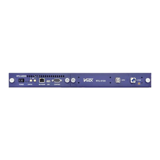
4.2.1 Front Panel Front Panel: RTU-4000 Chassis with RTU-4100 Optical Modules 4.2.2 Back Panel RTU-4000 Back Panel • Chassis GND - Ground point for the RTU unit • Alarm Contacts – Local alarm contacts • Control interface – DB25 female port: Power and Communication •... -
Page 10: Oxa4000 Optical Switch (Optional)
OXA4000 Specification Sheet at www.veexinc.com. Switch Installation Optical Switches are rack mounted at the same location as the RTU-4000/RTU- 4100, regardless if the installation is at the CO or the CO-LO. The OXA4000 series Optical Switch is available in various configurations. The OXA4000 can be configured as an optical switch or as an FWDM optical switch. -
Page 11: Electrical Equipment Safety Guidelines
• If possible, send another person to get medical aid. Otherwise, assess the condition of the victim and then call for help. • Determine whether the person needs rescue breathing or external cardiac compressions, and then take appropriate action. RTU-4000/RTU-4100 User Manual, D07-00-132P-RevA01 Page 11 of... -
Page 12: Rtu-4000/Rtu-4100 Hardware Installation
RTU-4000/RTU-4100 Hardware Installation The RTU-4000 accommodates a standard 19-inch mounting rack. Important! Only trained and qualified personnel should be allowed to install, replace, or service this equipment. Improper or unsafe use can cause physical harm and damage your equipment. Read the... -
Page 13: Chassis Lifting Guidelines
Chassis Lifting Guidelines A fully configured RTU-4000 chassis, with RTU-4100 OTDR Module installed, is not intended to be moved frequently. Before installing, plan chassis placement and ensure that your site is properly prepared so you can avoid having to move the chassis later to accommodate power sources and network connections. - Page 14 Always ensure the system receives sufficient airflow such that it will operate within the specified operating temperature range. RTU-4000/RTU-4100 User Manual, D07-00-132P-RevA01 Page 14 of 44...
-
Page 15: Connecting Power
Connecting Power For the AC power option, use only the AC power adapters and cables provided by VeEX. Take care when connecting units to the power supply so that wiring is not overloaded. RXT-4000/RXT-4100 Connecting Power 5.5.1 Powering on/off the unit To power on the unit: •... -
Page 16: Connecting To Rtu Probe
Probe Configuration Tool must be used. See the Assigning static IP address to probe section of this user manual. Assign Unique IP address The factory default IP address 192.168.100.250 must be changed for each probe to uniquely identify it. RTU-4000/RTU-4100 User Manual, D07-00-132P-RevA01 Page 16 of 44... -
Page 17: Probe Configuration Tool
Opening Configuration Tool To set the IP of the RTU-4100 use the latest version of the VeEX Probe Configuration Tool (Ver. 1.3.3) or higher software application and an Ethernet cable. To launch the Probe Configuration Tool via Ethernet configuration: 1. -
Page 18: Connecting Configuration Tool To Probe
Connecting Configuration Tool to probe To connect the Probe Configuration Tool via Ethernet: 1. Click the Select Probe Type drop-down list box arrow, and then select RTU-4000. 2. Select the Ethernet Port option button and enter the RTU IP address. - Page 19 After opening the serial port and connecting the probe to the Probe Configuration Tool, follow the instructions below to assign a static IP address so that you can connect to the probe via a web browser or with VeSion, as well as perform software updates, as needed. RTU-4000/RTU-4100 User Manual, D07-00-132P-RevA01 Page 19 of 44...
-
Page 20: Assigning Static Ip Address To Probe
• Local Gateway: Gateway IP for the probe. Connecting the Unit to Ethernet After assigning a new static IP address to the probe, connect the unit to your network via the Ethernet port with the Ethernet cable. RTU-4000/RTU-4100 User Manual, D07-00-132P-RevA01 Page 20 of 44... -
Page 21: Using Rtu4000/Rtu4100 In Standalone Mode
Optical Switch and select the desired test access port. • OTDR: • View basic OTDR information • Define the TCP port for Remote Control software, such as the VeEX Fiberizer Desktop or other third-party external software used to communicate with the RTU when making measurements •... -
Page 22: Setting Monitoring Parameters
For more details, see OTDR Menu. 4. If the RTU will be accessed also from Fiberizer Desktop, set the integration with Fiberizer Desktop. For more details, see 14.0 Remote Control RTU Using Fiberizer Desktop. RTU-4000/RTU-4100 User Manual, D07-00-132P-RevA01 Page 22 of 44... -
Page 23: Integration Menu
Integration with VeSion and/or an external server allows you to receive event notifications on the fibers being monitored. For more information on VeSion, see 15.0 VeSion Overview. To complete integration with the VeEX VeSion server, click Integration VeSion, enter information in the corresponding fields, and then click Apply. Settings for VeSion integration The parameters (Server IPv4 address, Server TCP port, Device number) can be obtained from your system administrator. -
Page 24: Rtu Menu (About, Name And Date/Time)
To change the Date/Time on the RTU to match your local time zone, select RTU Date/Time, set the date and time, and then click Apply. Setting Date/Time for RTU In the About section, you can check details about your RTU. To do that, select RTU About. RTU-4000/RTU-4100 User Manual, D07-00-132P-RevA01 Page 24 of 44... - Page 25 RTU About screen RTU-4000/RTU-4100 User Manual, D07-00-132P-RevA01 Page 25 of 44...
-
Page 26: Otau Menu
OTAU to view the device model, serial number, and available ports. Set the desired port number in the Switch to port drop-down list box, and then click Switch to move the switch to the desired test port. Setting OTAU port RTU-4000/RTU-4100 User Manual, D07-00-132P-RevA01 Page 26 of 44... -
Page 27: Otdr Menu
The Advanced measurement parameters section allows the timing and number of points of measurements to be set. Other parameters available when using Manual mode are: • Network and fiber properties • Trace analysis parameters (thresholds) • Span parameters RTU-4000/RTU-4100 User Manual, D07-00-132P-RevA01 Page 27 of 44... -
Page 28: Measurement History
For more information, see Section 13.2 Editing a Reference Trace. 12.1.2 Measurement history Measurement results are saved and can be accessed at a later time to view results as graphs, reports, or to download. Measurement history RTU-4000/RTU-4100 User Manual, D07-00-132P-RevA01 Page 28 of 44... -
Page 29: Monitoring
2. Enter information in the corresponding fields and click Add. By default, the Name field is populated automatically with the date and time it was created. 3. Click Monitoring Tests, and then click the test name on the list. The Test Settings page appears. RTU-4000/RTU-4100 User Manual, D07-00-132P-RevA01 Page 29 of 44... -
Page 30: New Reference Traces And Thresholds
To upload the reference traces, click the upload link, then follow the instructions on the screen. You can upload several reference traces. To let the RTU set reference traces automatically, click the let link, then set the analysis values in the Measure reference traces automatically box. RTU-4000/RTU-4100 User Manual, D07-00-132P-RevA01 Page 30 of 44... - Page 31 To set new thresholds, click the Change link from the Test Settings box. The Change test thresholds box appears. Enter new threshold values in the corresponding fields and click Apply. Setting new thresholds RTU-4000/RTU-4100 User Manual, D07-00-132P-RevA01 Page 31 of 44...
-
Page 32: Editing A Reference Trace
Fiberizer Desktop. If uploading a reference trace, edit the event table to add missing events. For more details, see the Fiberizer Desktop User Manual at www.veexinc.com. Viewing the measurement result and editing it RTU-4000/RTU-4100 User Manual, D07-00-132P-RevA01 Page 32 of 44... -
Page 33: Enable Monitoring
OTDR measurements and editing event tables before manually editing a Reference Trace. 13.3 Enable monitoring 13.3.1 Enabling monitoring mode To enable RTU monitoring, click Monitoring Settings, then click the Enable button. Enabling general monitoring RTU-4000/RTU-4100 User Manual, D07-00-132P-RevA01 Page 33 of 44... -
Page 34: Monitoring Results
After monitoring is enabled, the test measurement uses the designated reference trace and any change notifications about trace events will be sent automatically. You can view monitoring results and statuses by clicking Monitoring Tests. Test results table RTU-4000/RTU-4100 User Manual, D07-00-132P-RevA01 Page 34 of 44... - Page 35 When viewing a failed trace, you can compare it with the reference trace by clicking the Show reference button in the top left corner. An example of a last failed trace compared to the reference trace is shown below. A failed trace compared against the reference trace. RTU-4000/RTU-4100 User Manual, D07-00-132P-RevA01 Page 35 of 44...
-
Page 36: Remote Control Rtu Using Fiberizer Desktop
To perform a measurement directly from the RTU-4100 again (not the external software), disable the TCP Proxy function in the RTU-4100 Web Interface software by clicking OTDR RTU #####, then clicking the Disable button. RTU-4000/RTU-4100 User Manual, D07-00-132P-RevA01 Page 36 of 44... - Page 37 After Fiberizer Desktop is initialized, click OK and proceed with the measurement. For more information on how to use Fiberizer Desktop, see the Fiberizer Desktop User Manual at www.veexinc.com. RTU-4000/RTU-4100 User Manual, D07-00-132P-RevA01 Page 37 of 44...
-
Page 38: Vesion Overview
RF Monitoring (Forward and Return), MPEG, Burst Demodulation, PNM, and Sweep, Fiber monitoring (RFTS), and Ethernet tests in addition to being able to link with the VeEX R300 Server Billing and Work order management system. Results can be accessed anywhere, anytime, and at any location. -
Page 39: Upgrading Rtu-4000/Rtu-4100 Software
16.0 Upgrading RTU-4000/RTU-4100 Software To upgrade the probe software to the most recent version: 1. Download the software upgrade zip file from the product page on the VeEX website, www.veexinc.com, and then extract the files to a location on your hard drive. -
Page 40: Warranty And Software
• Replace hardware which prove to be defective provided that the products that the customer elects to replace are returned to VeEX Inc. by the customer, along with Proof of Purchase, within thirty (30) days of the request by the customer, freight prepaid. - Page 41 • Damage occurred from operating the unit outside of the environmental specifications for the product • Improper installation by the customer RTU-4000/RTU-4100 User Manual, D07-00-132P-RevA01 Page 41 of 44...
-
Page 42: Product Specifications
18.0 Product Specifications The most recent product specifications can be found on the VeEX web site at www.veexinc.com. RTU-4000/RTU-4100 User Manual, D07-00-132P-RevA01 Page 42 of... -
Page 43: Certifications And Declarations
All applicable products imported into the EU market after July 1, 2006 must pass RoHS compliance. For more information about RoHS as it relates to VeEX Inc, go to the VeEX web site at www.veexinc.com\ROHS. RTU-4000/RTU-4100 User Manual, D07-00-132P-RevA01... -
Page 44: About Veex
VeEX Inc., an innovative, customer-focused communications test and measurement company, develops next generation test and monitoring solutions for telecommunication networks and services. With a blend of advanced technologies and vast technical expertise, VeEX’s products diligently address all stages of network deployment, maintenance, field service turn-up, and integrate service verification features across DSL, Fiber Optics, CATV/DOCSIS, Mobile backhaul and fronthaul (CPRI/OBSAI), next generation Transport Network, Fibre Channel, Carrier &...
Need help?
Do you have a question about the RTU-4000 and is the answer not in the manual?
Questions and answers