Table of Contents
Advertisement
Quick Links
Please direct all questions to your local VeEX Sales Office, Representative, or Distributor. Or, contact VeEX technical support at
www.veexinc.com. Copyright 2014 VeEX Incorporated. All rights reserved.
No part of this user manual may be reproduced, translated into a foreign language, or be transmitted electronically without prior
agreement and written consent of VeEX Incorporated as governed by International copyright laws. Information contained in this
manual is provided "as is" and is subject to change without notice. Trademarks of VeEX Incorporated have been identified where
applicable, however the absence of such identification does not affect the legal status of any trademark.
Page 1 of 1
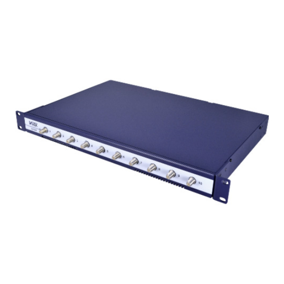
CX180F/CX180R
Forward and Return Path Monitoring System
Hardware Installation Guide
CX180F_R Hardware Installation Guide D07-00-018 Rev C00
USER MANUAL
Advertisement
Table of Contents

Related Manuals for VeEX CX180F


Summary of Contents for VeEX CX180F
- Page 1 VeEX Incorporated as governed by International copyright laws. Information contained in this manual is provided “as is” and is subject to change without notice. Trademarks of VeEX Incorporated have been identified where applicable, however the absence of such identification does not affect the legal status of any trademark.
-
Page 2: Table Of Contents
4.3.3 Grounding ....................... 6 4.4 safety Guidelines ......................6 5.0 InsTAllATIon ...................8 5.1 Installing the CX180F/R in a Rack ................8 5.2 Connecting the RF Ports ....................9 5.3 Connecting the Power ....................10 5.4 disconnecting the Power .................... 10 5.5 starting the system ..................... -
Page 3: Introduction
VeEX Inc. The software is protected by copyright and contains trade secrets of VeEX Inc or VeEX’s licensors. The purchaser of this device agrees that it has received a license solely to use the software as embedded in the device, and the purchaser is prohibited from copying, reverse engineering, decom-... -
Page 4: Safety Information
Grounding Protective earth conductor terminal. The location of the earth ground on the CX180F/R is shown below (DC powered version). Hot Surface Indicator Panels and connectors may be hot. -
Page 5: Getting Started
4.0 GeTTInG sTARTed 4.1 What’s Included The following items are included in the box: USB/Serial Port adaptor Mounting brackets AC Power adaptor Documentation CD 4.2 Tools Required Phillips Screwdriver 4.3 Product Features and Characteristics Primary power Secondary power Serial port Ethernet port Ground Page 5 of 13... -
Page 6: Front Panel
4.3.1 Front Panel The front panel of the CX180F/R contains input connectors and status LEDs. 4.3.2 Rear Panel Connector label Function DC1-DC2 Power input, DC1 main input, DC2 (if ordered) secondary input RS-232 Serial console port for system management 10/100 BT... - Page 7 Chassis lifting Guidelines A fully configured CX180F/R weighs approximately 11 pounds (5 Kilograms). The chassis is not intended to be moved frequently. Before you install the CX180F/R, plan chassis placement and ensure that your site is properly prepared so you can avoid having to move the chassis later to accommodate power sources and network con- nections.
-
Page 8: Installation
5.0 InsTAllATIon This chapter explains how to mount and physically install the CX180F/R. 5.1 Installing the CX180F/R in a Rack The CX180F/R is designed to accommodate a standard 19-inch mounting rack. Caution must be exercised when rack mounting this or any other type of equipment. -
Page 9: Connecting The Rf Ports
When connecting the QAM/Burst Receiver ports to the HFC network, take note of the following: When connecting the F-connector on the cable to the RF connector on the CX180F/R chassis, always use a torque wrench to set the tightness to 15 inch-lbs. Do not simply hand-tighten the F-connectors. -
Page 10: Connecting The Power
2. Unplug the power plug from the DC power receptacle. 5.5 starting the system After installing the CX180F/R and connecting the required cables, please configure the IP address of the system to match the specific operation needs. Page 10 of 13... -
Page 11: Power Consumption
Replace hardware that proves to be defective provided that the products that the customer elects to replace is returned to VeEX Inc by the customer, along with proof of purchase, within thirty (30) days of the request by the customer, freight prepaid. -
Page 12: Certifications And Declarations
EU market after July 1, 2006 must pass RoHS compliance. Click here for ROHS Statement relating to VeEX products safety and Regulatory Agency Compliance The CX180F/R complies with the safety and regulatory agency standards listed below when installed in accor- dance with this guide. Product safety... -
Page 13: About Veex
Operation of this equipment in a residential area is likely to cause harmful interference, in which case the user will be required to correct the interference at his own expense. Changes or modifications not expressly approved by VeEX, Inc. may void the user’s authority to use this equip- ment.
Need help?
Do you have a question about the CX180F and is the answer not in the manual?
Questions and answers