VeEX FX150 User Manual
Otdr series
Hide thumbs
Also See for FX150:
- User manual (128 pages) ,
- User manual (109 pages) ,
- Quick start manual (9 pages)

Related Manuals for VeEX FX150


Summary of Contents for VeEX FX150
- Page 1 OTDR Series e-Manual, D07-00-076P-RevC00 Page 1 of 107 OTDR Series e-Manual, D07-00-076P-RevC00 Page 1 of 107 • FX150 • FX300 • MTTplus-410 • RXT-4100 OTDR Series • TX300s...
-
Page 2: Table Of Contents
FX150 Keypad ............................21 5.5.3 FX150 Screen Navigation ........................22 5.5.3.1 View/Hide side menu panels ......................23 5.5.4 Setting up FX150 WiFi ......................... 24 5.5.4.1 Access WiFi option ........................24 5.5.4.2 Connect to a WiFi network ......................25 ....................26... - Page 3 OTDR Series e-Manual, D07-00-076P-RevC00 Page 3 of 107 6.8.1 Fiber Scope Overview .......................... 39 6.8.2 Connecting the Fiber Scope ....................... 40 6.8.3 Setup ..............................41 6.8.4 Analysis ..............................41 6.8.5 Capture Screen ............................. 42 6.8.6 Captured Files ............................43 6.8.7 Connector Face Analysis ........................
- Page 4 Saving/Printing Traces to PDF/USB/Bluetooth ................. 99 7.7.3 File Operations ........................... 100 ..........................101 BOUT 8.0 REVEAL SOFTWARE ....................102 9.0 WARRANTY AND SOFTWARE ................103 10.0 PRODUCT SPECIFICATIONS ................. 105 11.0 CERTIFICATIONS AND DECLARATIONS .............. 106 12.0 ABOUT VEEX ......................107...
-
Page 5: About This User Manual
VeEX, VePAL, Sunrise Telecom, Agizer, Optixsoft, Sunlite, Sunset, RXT, MTT, FX, TX, OPX, and Fiberizer are trademarks of VeEX, Inc. and/or its affiliates in the USA and certain other countries. All trademarks or registered trademarks are the property of their respective companies. -
Page 6: Product Introduction
OTDR Series e-Manual, D07-00-076P-RevC00 Page 6 of 107 Product Introduction The FX150, FX300, MTTplus, RXT, and TX300s feature an OTDR optimized for the installation and troubleshooting of FTTx, PON, CATV, Mobile Backhaul, and Metro fiber networks. Platform Highlights (FX150/FX300/MTTplus/RXT/TX300s) • Robust, compact hand-held design for demanding field test environments •... -
Page 7: Key Features
(check with factory on availability) • Fiberizer Cloud to upload fiber test data • VeExpress to check/upgrade software and installed options status (not available on FX300 or FX150) Key Features • FTTx optimized parameters for best dead zones • Filtered 1625 or 1650 nm OTDR port for in-service measurements •... -
Page 8: Package Contents
• OTDR (FX300, FX150, TX300S OTDR blade, RXT-4100 module or MTTplus-410 module) • AC/DC adaptor • Input: 100-240 VAC (50/60 Hz), 1.5A max - (MTTPLUS: 5.3A max; FX150: 1.5A max) • Output: 16VDC - (MTTPLUS: 15VDC; FX150: 12VDC) • Ethernet cable (FX300, TX300S OTDR blade, RXT module or MTTplus module) •... -
Page 9: Safety Information
Do not operate the instrument in the presence of flammable gases or fumes or any other combustible environment. VeEX Inc. assumes no liability for the customer's failure to comply with safety precautions and requirements. -
Page 10: Theory Of Operation
OTDR Series e-Manual, D07-00-076P-RevC00 Page 10 of 107 Theory of Operation OTDR The principle of OTDR operation is based on measuring the Rayleigh back scattering signal when a single powerful optical pulse passes through an optical fiber. The weak back scattering signal is registered by an optical receiver, converted into digital form and averaged many times. -
Page 11: Light Source
OTDR Series e-Manual, D07-00-076P-RevC00 Page 11 of 107 Light Source An optional light source is available and designed for generating continuous optical radiation. The light source output is the same as the OTDR port and uses the same laser diodes and optical splitter. -
Page 12: Basic Operation
OTDR Series e-Manual, D07-00-076P-RevC00 Page 12 of 107 Basic Operation Test Ports and Interfaces OTDR testing: The optical fiber under test is connected to either the OTDR or OTDR Aux (Filtered SM or MM) port on the top panel. The type of the optical fiber connector must correspond to the OTDR connector or adaptor type, including the connector polish. - Page 13 OTDR Series e-Manual, D07-00-076P-RevC00 Page 13 of 107 T T X X 3 3 0 0 0 0 s s T T o o p p V V i i e e w w R R x x T T - - 4 4 1 1 0 0 0 0 O O T T D D R R M M o o d d u u l l e e...
-
Page 14: Front Panel Layout
OTDR Series e-Manual, D07-00-076P-RevC00 Page 14 of 107 Front Panel Layout The picture below depicts the TX300s. Layout will vary depending on FX150, FX300, MTTplus, or RXT platforms. 5.2.1 LED Indicators Power/Charge LED - indicates battery charging is in progress. LED turns off when battery is fully charged. -
Page 15: Menu Navigation
“Getting started” information is displayed after power up. Select a Test Application • FX150: Application #1 is loaded by default. Select OTDR, VFL, OPM, OLS by clicking the icon on the main menu. The Fiberscope icon can be found on the Advanced Tools screen. -
Page 16: Mttplus Overview
OTDR Series e-Manual, D07-00-076P-RevC00 Page 16 of 107 MTTplus Overview 5.3.1 MTTplus Side View... -
Page 17: Mttplus Control Panel
OTDR Series e-Manual, D07-00-076P-RevC00 Page 17 of 107 5.3.2 MTTplus Control Panel • Power: Press for 2 seconds to turn the test set ON or OFF (prevents accidental ON/OFF) If a test is running when the power off is started, test is terminated and results may not be automatically saved. -
Page 18: Rxt Overview
OTDR Series e-Manual, D07-00-076P-RevC00 Page 18 of 107 RxT Overview... -
Page 19: Rxt Front Panel
OTDR Series e-Manual, D07-00-076P-RevC00 Page 19 of 107 5.4.1 RxT Front Panel • Power: Press for 2 seconds to turn the test set ON or OFF (prevents accidental ON/OFF) • Cursor Keys: Application dependent; May offer alternative GUI Navigation to touch screen (e.g. -
Page 20: Getting Started
OTDR Series e-Manual, D07-00-076P-RevC00 Page 20 of 107 5.4.2 Getting Started A Quick Guide is always present in the Home screen after boot up. This screen can be displayed at any time from any screen. The test port group is assigned to the Fiber application when the 410 module is installed. All options associated with the 410 OTDR module will be installed. -
Page 21: Fx150 Overview
5.5.1 FX150 Test Ports V V F F L L / / O O P P M M / / A A u u x x - - O O T T D D R R / / O O T T D D R R - - O O L L S S 5.5.2... -
Page 22: Fx150 Screen Navigation
O O T T D D R R S S c c r r e e e e n n Use the top tabs of the FX150 screen to access test measurement controls and view results. On the bottom bar, you can see: •... -
Page 23: View/Hide Side Menu Panels
5.5.3.1 View/Hide side menu panels The left and right panels of the display provide icons to access key functions of the FX150. These panels can be turned on or off to enable a better view of the application screens. Use the shift keys located on the left and right sides of the unit to toggle on/off the left and right menu panels. -
Page 24: Setting Up Fx150 Wifi
OTDR Series e-Manual, D07-00-076P-RevC00 Page 24 of 107 5.5.4 Setting up FX150 WiFi The FX150 unit contains an optional built-in WiFi interface allowing you to easily transfer OTDR traces and upgrade software on the unit. 5.5.4.1 Access WiFi option 1. Press Utilities or the HOME key, and then press Bluetooth/WiFi. -
Page 25: Connect To A Wifi Network
OTDR Series e-Manual, D07-00-076P-RevC00 Page 25 of 107 5.5.4.2 Connect to a WiFi network 1. Press Scan to see all networks 2. Select one of the available networks and the Edit Settings key will appear to the right. Once selected, an Edit Settings function key appears to the right. 3. -
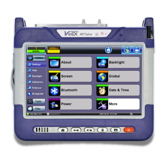
Page 26: Customizing Your Tester
OTDR Series e-Manual, D07-00-076P-RevC00 Page 26 of 107 Customizing Your Tester You can customize the settings on your OTDR device in the Utilities>Settings menu: • About: Displays serial #, MAC address, software version, software options installed and related product information •... - Page 27 OTDR Series e-Manual, D07-00-076P-RevC00 Page 27 of 107 • Global: Various settings including: • General • Language: English, German, French, Chinese, Japanese, Korean and others (de- pends on software version). You must reboot the device to fully activate the new language •...
-
Page 28: Test Fiber And Initial Preparation Introduction
OTDR Series e-Manual, D07-00-076P-RevC00 Page 28 of 107 Test Fiber and Initial Preparation Introduction Dirt, dust, and other contaminants severely impact high-speed data transmission in optical fibers and dirty connector end-faces are often the #1 cause of link failures. High insertion loss and/or high back reflection can result in transmission loss or high bit errors and poor BER. -
Page 29: Contamination
OTDR Series e-Manual, D07-00-076P-RevC00 Page 29 of 107 Contamination Optical connectors are susceptible to contamination from air borne particles and human body oils when exposed. Left over liquid residue from improper cleaning can also leave the fiber end face contaminated. The smaller the fiber core, the more severe the problem is likely to be, especially when you consider that fiber core diameters can range from 62.5 microns all the way down to 8 microns in size. -
Page 30: Cleaning Procedure
OTDR Series e-Manual, D07-00-076P-RevC00 Page 30 of 107 Cleaning Procedure To ensure proper and effective cleaning of optical fiber connectors and interfaces, please equip yourself with the following cleaning materials: • Isopropyl alcohol • Lint free soft tissues • Ferrule cleaners (1.25mm and 2.5mm versions) •... -
Page 31: Best Practices
OTDR Series e-Manual, D07-00-076P-RevC00 Page 31 of 107 Best Practices • Never touch the end face of an optical fiber connector with your hands or fingers. • Always install dust caps on unplugged fiber connectors. • Store unused dust caps in a re-sealable plastic bag to prevent dust accumulating. •... -
Page 32: Connectors
OTDR Series e-Manual, D07-00-076P-RevC00 Page 32 of 107 Connectors 6.5.1 Connector Types In fiber optic networks, you will come into contact with many different connector types, the most common being described below: ST Connector ST stands for Straight Tip-a quick release bayonet style connector developed by AT&T. STs were predominant in the late 80s and early 90s and are still one of the most commonly used fiber optic connectors in networking applications. - Page 33 OTDR Series e-Manual, D07-00-076P-RevC00 Page 33 of 107 LC Connector LC stands for Lucent Connector. It is a small form-factor fiber optic connector that uses a 1.25 mm ferrule, which is half the size of the ST / SC connectors. It uses a standard ceramic ferrule connector.
-
Page 34: Connector Performance And Polishing
OTDR Series e-Manual, D07-00-076P-RevC00 Page 34 of 107 E2000 Connector Developed by Diamond, this connector has proven its performance worldwide in CATV and telecommunication networks. The connector features a spring-loaded shutter used to protect the ferrule from dust and scratches, and to provide increased safety protection. It uses a high precision Zirconia full ceramic ferrule with an insertion loss of 0.1dB. - Page 35 OTDR Series e-Manual, D07-00-076P-RevC00 Page 35 of 107 • Ultra Physical Contact (UPC) - The UPC style ferrule has the shape of the PC style, except they are polished with several grades of polishing film that allows for an ultra- smooth surface.
-
Page 36: Fiber Cables And Fiber Patchcords
OTDR Series e-Manual, D07-00-076P-RevC00 Page 36 of 107 Fiber Cables and Fiber Patchcords 6.6.1 Fiber Cable Styles of Fiber Optic Cable vary in outer appearance, materials, application, features, and benefits. In OTDR applications, you will regularly come across the following types: Bare Fiber •... -
Page 37: Fiber Patchcord
OTDR Series e-Manual, D07-00-076P-RevC00 Page 37 of 107 2, 4, 6, 8, 12, 24, 48, 72, 144 or greater fiber counts • Outer Jacket can be of a variety of materials • Usually longer runs and can be terminated with almost any style of connector Ribbon •... - Page 38 OTDR Series e-Manual, D07-00-076P-RevC00 Page 38 of 107 Color Coding The buffer or jacket on patchcords is often color-coded to indicate the type of fiber used. Connector boot The strain relief “boot” that protects the fiber from bending at a connector is color-coded to indicate the type of connection.
-
Page 39: Inserting The Fiber
Mismatched connector types will damage the optical end faces and the test set. Note: If the optical fiber is not aligned properly and/or completely connected, it will cause serious loss and reflection. Fiber Scope Utility (FX150, FX300, MTTplus, RxT) 6.8.1 Fiber Scope Overview DI-1000 Digital Fiber Scope The DI-1000 uses auto focus and capture the image and grade the connector’s health and... -
Page 40: Connecting The Fiber Scope
Fiber Scope Expert option is installed. 1. Connect the Fiber Scope to the test set, using any available USB port (Older analog fiber scopes require a USB adapter). To connect to the FX150 microUSB port, use an approved OTG cable. -
Page 41: Setup
OTDR Series e-Manual, D07-00-076P-RevC00 Page 41 of 107 6.8.3 Setup • File Prefix: Enter any name to identify the cable, site, technician, job, etc. • Starting #: Enter the initial sequence number. This number will increase with each image captured. •... -
Page 42: Capture Screen
OTDR Series e-Manual, D07-00-076P-RevC00 Page 42 of 107 6.8.5 Capture Screen • Freeze / Resume: Stops the real time video so users can look at the static picture. • Analysis On / OFF: Turn the Auto Analysis ON and OFF (software option). •... -
Page 43: Captured Files
OTDR Series e-Manual, D07-00-076P-RevC00 Page 43 of 107 6.8.6 Captured Files Use check boxes to select one (View) or two (Compare) files. • Clear All: Deletes all files saved in memory. • Delete: Deletes all selected files. • Compare: If two files are selected, they can be compared. For example, pictures of the same connector before and after cleaning. -
Page 44: Connector Face Analysis
OTDR Series e-Manual, D07-00-076P-RevC00 Page 44 of 107 6.8.7 Connector Face Analysis Select a file from the Captured Files screen and press the Analysis button. • Open: Provides a visual navigation tool to select files. Use the stylus to slide left or right until the correct file is in view, tap on the image to load it. -
Page 45: Connector Face Analysis Results Table
OTDR Series e-Manual, D07-00-076P-RevC00 Page 45 of 107 6.8.8 Connector Face Analysis Results Table Select the Result Table tab. The test set displays a table with all numeric results from the analysis. Catalogs, Defect and Scratch events found for all four zones. Scratch requirements refer to width. -
Page 46: Html Report
OTDR Series e-Manual, D07-00-076P-RevC00 Page 46 of 107 6.8.8.1 HTML Report The Fiber Scope test report can be viewed in HTML format. -
Page 47: Pdf Report
OTDR Series e-Manual, D07-00-076P-RevC00 Page 47 of 107 6.8.8.2 PDF Report The Fiber Scope test report can be viewed in PDF format. -
Page 48: Managing Fiberscope Results With File Manager
OTDR Series e-Manual, D07-00-076P-RevC00 Page 48 of 107 6.8.9 Managing Fiberscope Results with File Manager 1. Go to Utilities >Files >Saved. All results stored in the test set are displayed. 2. Use the to select the desired files. 3. Tap on any column header to sort by that specific parameter (FS Analysis or Fiber Scope). Tap again to change the sorting order. -
Page 49: File Manager Filters
OTDR Series e-Manual, D07-00-076P-RevC00 Page 49 of 107 6.8.9.1 File Manager Filters File Filters make it easier to isolate desired types of results from all other test results stored in the test set. It also reduces the number of pages displayed. To activate filters, use the stylus to tap the + icon. -
Page 50: Fiber Scope Image Management Software (Vis400D Only)
OTDR Series e-Manual, D07-00-076P-RevC00 Page 50 of 107 6.8.10 Fiber Scope Image Management Software (ViS400D only) Detailed PC-based Fiber Inspection Monitor & Analysis: Compatible with VIS400D • IEC 61300-3-35 Profiles • SMF UPC >45 dB • SMF APC • SMF PC RL>26 dB •... -
Page 51: Fiber Scope Image Management Software (Vs-500 And Di-1000 Only)
OTDR Series e-Manual, D07-00-076P-RevC00 Page 51 of 107 6.8.11 Fiber Scope Image Management Software (VS-500 and DI-1000 only) Detailed PC-based Fiber Inspection Monitor & Analysis: Compatible with DI-1000 Fiber Scope • IEC 61300-3-35 Profiles Analysis Profile Parameters: • AnalysisParam1: SMF UPC >45 dB •... - Page 52 OTDR Series e-Manual, D07-00-076P-RevC00 Page 52 of 107 • AutoFreeze: Turn ON/OFF Auto Freeze when Fiber Scope image is in Focus • UnFocus before Freeze: Select if you wish to unFocus Image prior to Freezing image • Show Table: Select to switch from connector image to Table view Click the to pop up the File Management Window.
- Page 53 OTDR Series e-Manual, D07-00-076P-RevC00 Page 53 of 107 • About: To check the Fiberizer Scope software revision for the Fiber Scope • Exit: To quit the Fiberizer Scope program.
-
Page 54: Visual Fault Locator (Vfl)
Never look directly into the VFL’s light. It is a Class II laser and emits laser radiation that will harm your eyes. Use the Home icon (FX150/FX300) or App key (FX300) to toggle between active test applications (OTDR, OPM, VFL). -
Page 55: Using The Vfl
OTDR Series e-Manual, D07-00-076P-RevC00 Page 55 of 107 6.9.1 Using the VFL To operate the VFL: 1. Make sure laser is turned off. Remove connector covers from the cable. 2. Connect the fiber to the VFL port located at the top of the unit. The VFL interface is fitted with universal 2.5mm sleeve accepting all 2.5 mm connector ferrules. -
Page 56: Optical Light Source (Ols)
OTDR Series e-Manual, D07-00-076P-RevC00 Page 56 of 107 9. Press Turn OFF. 10. Disconnect the cable and replace covers. When not in use, disconnect the cord from the port, replace dust covers, and keep the port cap securely closed. For patchcords with dark cabling or any outdoor cable or bend-insensitive patchcords (armored cables), VFL will not work because there is no way to bend fibers. -
Page 57: 6.10.1 Accessing And Setting Up The Optical Light Source
OTDR Series e-Manual, D07-00-076P-RevC00 Page 57 of 107 6.10.1 Accessing and setting up the Optical Light Source To access and set up the OLS option: 1. Make sure that the Optical Light Source option is installed on the test unit. 2. -
Page 58: 6.10.2 Using The Optical Light Source
OTDR Series e-Manual, D07-00-076P-RevC00 Page 58 of 107 6.10.2 Using the Optical Light Source To use the OLS: 1. Connect a patchcord between the OLS and OPM test ports. 2. Select Optical Light Source from the main menu. The OLS screen appears. 3. -
Page 59: Optical Power Meter (Opm)
Note: Only optical power meters (e.g. Built-in, UPM-100 or FX40 series meters) approved by VeEX are supported. To see the most recent OPM specifications, go www.veexinc.com. Home icon (FX150/FX300) or App key (FX300) to toggle between active test Use the applications (OTDR, OPM, VFL). -
Page 60: 6.11.1.1 Usb Opm Setup Options
OTDR Series e-Manual, D07-00-076P-RevC00 Page 60 of 107 To access and set up the internal OPM: 1. Check the test ports to ensure that the Optical Power Meter option is installed on the test unit. 2. Power on the unit. Test App 1 – Test Mode Selection is loaded by default. Select Fiber testing, and then press OK. -
Page 61: 6.11.1.2 Setting Pass/Fail Limits
OTDR Series e-Manual, D07-00-076P-RevC00 Page 61 of 107 To calibrate the Loss meter to the LS: 1. Connect the LS the OPM using a short patch cord. 2. Tap the Reference button to record the 0dB point. A reference point is established and the calibrated LS can be connected to the far-end of the fiber to measure the loss. -
Page 62: 6.11.2 Using The Built-In Opm
OTDR Series e-Manual, D07-00-076P-RevC00 Page 62 of 107 6.11.2 Using the built-in OPM 1. Connect the fiber to the OPM port located at the top of the unit. 2. Power on the unit. 3. Select Test App 1 or Fiber to see the OTDR/VFL/OLS/OPM selection screen. 4. - Page 63 OTDR Series e-Manual, D07-00-076P-RevC00 Page 63 of 107 To calibrate the Loss meter to the LS: Note: For more information on patchcords, see 6.6.2 Fiber Patchcord. 1. Connect the LS to the OPM using a patch cord. 2. Tap the green dB button. 3.
-
Page 64: Optical Loss Test Set (Olts) (Not Currently Supported)
6.13 Results To view and save results using the FX150 meter: 1. On your device, select the results you wish to save, and then press Back. 2. To save locally, press Save. - Page 65 OTDR Series e-Manual, D07-00-076P-RevC00 Page 65 of 107...
-
Page 66: Working With The Otdr
Working with the OTDR Test Setup Note: Screens provided in this section are based on the V300 series OTDR. Slight differences may occur between FX150, FX300, MTTplus, or RxT platform screens when describing OTDR and OPM operation. 7.1.1 Initial Settings Wavelength: Select the wavelengths, which you wish to use to test the fiber. -
Page 67: Manual Mode
OTDR Series e-Manual, D07-00-076P-RevC00 Page 67 of 107 7.1.2 Manual mode To set test parameters manually, select Manual Mode. Manual Test Setup (page 1) Manual Test Setup (RxT-4111 only) - Page 68 OTDR Series e-Manual, D07-00-076P-RevC00 Page 68 of 107 OTDR Setup (Page 1): Test Parameters (all OTDR models) • Mode: Manual, Auto, VScout, or VScout Profiles (optional) • PON Type: Not A PON, Manual PON or Auto PON • 1st Splitter (manual mode) •...
- Page 69 OTDR Series e-Manual, D07-00-076P-RevC00 Page 69 of 107 Other Parameters • Auto Zoom Trace: Use this mode to auto scale the viewing window at the end of the test. Note: Disable this feature when using Realtime test mode. The Fiber/Connection Check is set to ON by default. Tap the checkbox to disable. •...
-
Page 70: Auto Mode
• Fiber properties - Refractive Index and Backscatter coefficient as provided by cable manufacturer • Real Time button - Used when checking initial connection, VFL testing or splice alignment (On the FX150, press the right side rocker button to expand the menu on the right side.) -
Page 71: V-Scout Mode (Optional)
OTDR Series e-Manual, D07-00-076P-RevC00 Page 71 of 107 • Auto Zoom Trace – Auto scale viewing window at end of test. • Front Panel Check – Report Insertion Loss and Reflectance and advise if acceptable or not. If testing PON or MUX, use a launch fiber between the OTDR and Splitter or MUX or disable this feature. - Page 72 OTDR Series e-Manual, D07-00-076P-RevC00 Page 72 of 107 • Information: Edits group information. Type: Link Start, Link End, Subscriber Splitter, Connector, APC Connector, Splice, Macrobend, Office Splitter, Unknown Splitter Ratio: Not present, 1x2, 1x4, 1x8, 1x16, 2x2, 2x4, 2x8, or 2x32 Comments: Enter information regarding the modification.
-
Page 73: Setting Up And Using V-Scout Mode
OTDR Series e-Manual, D07-00-076P-RevC00 Page 73 of 107 7.1.4.1 Setting up and Using V-Scout mode V-Scout has been improved to give the operator the ability to optimize automated testing further by creating custom V-Scout test plans. A unique profile can be created for specific test environments. -
Page 74: V-Scout Symbols
OTDR Series e-Manual, D07-00-076P-RevC00 Page 74 of 107 Pulse Width: Select 1-10 pulsewidths that you wish to use to build V-Scout Link Map by checking Enabled. An asterisk will mark any Pulse Width that you have already selected for use in your new test plan. Resolution: Choose Auto or manually select the available resolution you desire. - Page 75 OTDR Series e-Manual, D07-00-076P-RevC00 Page 75 of 107 Icon Description Angled Connector Loss >0.05 dB, Reflectance >-60 dB Macrobend (difference between two non-reflective events exceeding defined dB Threshold measured at different wavelengths Several aggregated or grouped events 1xN Splitter from the OLT side Loss >...
-
Page 76: Thresholds
OTDR Series e-Manual, D07-00-076P-RevC00 Page 76 of 107 Thresholds Threshold settings are available on page 2 of the Setup tab. This allows you to preset and enable measurement thresholds. Events will be placed into the table only if the Analysis threshold is met/exceeded. -
Page 77: Pass/Fail Thresholds
OTDR Series e-Manual, D07-00-076P-RevC00 Page 77 of 107 Splitters – Defines splitter loss values to be applied when building the LinkMap. 7.2.2 Pass/Fail Thresholds Events exceeding the Pass/Fail Thresholds are highlighted in Red in the Event table. Different Pass/Fail Thresholds values can be set for each test wavelength. Event Loss (splice, connectors) and Reflectance threshold settings determine if a detected anomaly should be reported and included in the event table including its event type (reflective or non-reflective). -
Page 78: Event Table
OTDR Series e-Manual, D07-00-076P-RevC00 Page 78 of 107 7.2.3 Event Table • Show Fiber Sections – Shows fiber section in event table. • Distance Unit – Sets metric for distance between fiber sections in viewing window (km, kft, feet, meter, miles). 7.2.4 Autosave Parameters •... - Page 79 OTDR Series e-Manual, D07-00-076P-RevC00 Page 79 of 107 • Real Time: To view trace in real time. Used when checking initial connection, VFL testing or splice alignment. • Fiber Index: Test counter. When saving test results, count auto increments and is added to filename.
-
Page 80: Cloud Credentials
OTDR Series e-Manual, D07-00-076P-RevC00 Page 80 of 107 7.2.5 Cloud Credentials The user can register for a Cloud account: https://cloud.fiberizer.com. After creating a Cloud Account, the user can then login and push test results into their account (Page 5 of Test Setup tab): •... -
Page 81: Making Measurements
Start button when acquisition is complete. For V- Scout measurements, the acquisition wavelength is also displayed. Press Stop to terminate the measurement manually, if required. Use the Home icon (FX150/FX300) or App key (FX300) to toggle between active test applications (OTDR, OPM, VFL). 7.3.1 Trace Display When a new measurement is started, only those traces will be displayed on the screen. -
Page 82: Events
OTDR Series e-Manual, D07-00-076P-RevC00 Page 82 of 107 Events 7.4.1 Event Table The Events table is available in all measurement modes. Select the Events tab to display the trace with events. The Event table displays all events found during the analysis including those added manually by the user. -
Page 83: Event Types
OTDR Series e-Manual, D07-00-076P-RevC00 Page 83 of 107 7.4.2 Event Types The Event is color coded depending on Threshold settings defined in the test setup. • Red indicates the event fails or exceeds the Pass threshold criteria. • Green indicates the event passes the Fail threshold criteria. 7.4.3 Event Editing Adding events:... -
Page 84: Measure Mode
User’s disposal. The Markers can be moved using the touchscreen or using the left/right buttons on the rubber keypad (not available on MTTplus or FX150). The Markers display the following: • Distance from the start of the trace to Marker “A”... -
Page 85: Zoom/Scroll Controls
OTDR Series e-Manual, D07-00-076P-RevC00 Page 85 of 107 At the top part of the screen next to the markers, the position of the marker with respect to the beginning of the optical fiber is indicated in kilometers, miles or feet. In the data line at the bottom of the screen you will see the parameters of the trace corresponding to the markers’... -
Page 86: Distance Measurements
OTDR Series e-Manual, D07-00-076P-RevC00 Page 86 of 107 7.5.2 Distance Measurements D D i i s s t t a a n n c c e e m m e e a a s s u u r r e e m m e e n n t t – – m m e e a a s s u u r r e e e e x x p p a a n n d d e e d d t t r r a a c c e e v v i i e e w w m m o o d d e e When a trace is displayed as show above, the fiber length is automatically measured from the start of the trace (or Span Begin) to each of the two markers and in between the markers. -
Page 87: Two Point Lsa (2-Pt Lsa)
OTDR Series e-Manual, D07-00-076P-RevC00 Page 87 of 107 • The data at the bottom of the screen displays: Distance between markers A-B • Loss between markers A-B in dB • Attenuation between markers A-B 7.5.3.2 Two Point LSA (2-Pt LSA) To increase the accuracy of a loss or attenuation measurement, a section of the trace preceding and following the marker A and marker B can be approximated by a straight line. -
Page 88: Reflectance Measurement
OTDR Series e-Manual, D07-00-076P-RevC00 Page 88 of 107 5. Position the first two markers on a section of backscatter preceding the event and position the last two markers on a section of backscatter after the event ensuring that enough pre/post backscatter is used to make an accurate measurement. Markers A and B should be placed on the left and right but as close to one another as possible. -
Page 89: Orl Measurement
OTDR Series e-Manual, D07-00-076P-RevC00 Page 89 of 107 7.5.6 ORL Measurement ORL is the total amount of light being reflected back towards the transmitter or source. This includes all backscatter and all reflections. The OTDR can calculate ORL from the fiber trace using the following procedure: 1. -
Page 90: Traces
OTDR Series e-Manual, D07-00-076P-RevC00 Page 90 of 107 Traces Select the Traces tab to view the active or measured OTDR traces. The color-coded blocks represent the corresponding trace viewed in the OTDR display. The OTDR can display up to ten traces simultaneously i.e. an active trace and nine additional traces. -
Page 91: Trace Properties
OTDR Series e-Manual, D07-00-076P-RevC00 Page 91 of 107 7.6.1 Trace Properties The traces in the memory are saved in BELLCORE, version 2.0 format. The OTDR trace files have the extension .sor which means Standard OTDR Record. These OTDR trace files can be opened by the software of other OTDR vendor applications provided the format is supported. - Page 92 OTDR Series e-Manual, D07-00-076P-RevC00 Page 92 of 107 T T r r a a c c e e I I n n f f o o r r m m a a t t i i o o n n - - M M e e a a s s u u r r e e m m e e n n t t •...
-
Page 93: Saving Otdr Traces
OTDR Series e-Manual, D07-00-076P-RevC00 Page 93 of 107 Span Begin and Span End Refer to section Launch/Receive fiber offset. The user can offset the length of an external launch fiber or patchcord, which is connected to the fiber under test; otherwise, it becomes part of the fiber span and analysis. The launch fiber can be offset or compensated in any of the following ways: •... -
Page 94: Saving Otdr Traces With Embedded Gps And Camera Image
OTDR Series e-Manual, D07-00-076P-RevC00 Page 94 of 107 7.6.3 Saving OTDR Traces with Embedded GPS and Camera Image 7.6.3.1 Obtaining GPS Coordinates To obtain the GPS coordinates for your current location: 1. Access Utilities>More>GPS/High Precision Clock. 2. Connect the antenna to the RF connector port (brass) located at the top of the unit. 3. -
Page 95: Adding Camera Image Otdr File (Mttplus Only)
OTDR Series e-Manual, D07-00-076P-RevC00 Page 95 of 107 7.6.5 Adding Camera Image OTDR file (MTTplus only) A Camera image can be added using the Manual Save only mode (AutoSave disabled) mode to display the Result AutoSaving pop up window. Enter all AutoSave field entries and select Generate PDF Report and/or select Add V-Scout Diagram. - Page 96 OTDR Series e-Manual, D07-00-076P-RevC00 Page 96 of 107...
-
Page 97: Results
OTDR Series e-Manual, D07-00-076P-RevC00 Page 97 of 107 Results The Results tab displays the following information pertaining to OTDR traces. To expand the selection or folder directory, tap on the arrow. An arrow pointing to the right indicates the branch is collapsed whereas an arrow pointing downwards indicates the branch is expanded. The traces are saved in the following folder directory hierarchy: •... -
Page 98: File Management
OTDR Series e-Manual, D07-00-076P-RevC00 Page 98 of 107 7.7.1 File Management F F i i l l e e L L o o c c a a t t i i o o n n • Select Files/Saved menu to access saved traces or results •... -
Page 99: Saving/Printing Traces To Pdf/Usb/Bluetooth
OTDR Series e-Manual, D07-00-076P-RevC00 Page 99 of 107 F F i i l l e e M M a a n n a a g g e e r r 7.7.2 Saving/Printing Traces to PDF/USB/Bluetooth P P r r i i n n t t i i n n g g / / S S a a v v i i n n g g R R e e s s u u l l t t t t o o P P D D F F / / U U S S B B / / B B l l u u e e t t o o o o t t h h The saved OTDR sor file can be exported in several ways: •... -
Page 100: File Operations
OTDR Series e-Manual, D07-00-076P-RevC00 Page 100 of 107 • Export to Bluetooth - transfers OTDR sor file via Bluetooth connection to a PC or Mobile phone. • Tablet. Requires Bluetooth dongle accessory Select the folder containing the test results you want to export to highlight it. Tap USB Export and select tree (“MyVeEX”) or Flat (same folder) in which to export to USB. -
Page 101: About Tab
OTDR Series e-Manual, D07-00-076P-RevC00 Page 101 of 107 F F i i l l e e O O p p e e r r a a t t i i o o n n s s Deleting Directories/Files 1. -
Page 102: Reveal Software
OTDR Series e-Manual, D07-00-076P-RevC00 Page 102 of 107 ReVeal Software For more information on using the ReVeal software, refer to the ReVeal User Manual at www.veexinc.com. -
Page 103: Warranty And Software
• Replace hardware which prove to be defective provided that the products that the customer elects to replace are returned to VeEX Inc. by the customer, along with Proof of Purchase, within thirty (30) days of the request by the customer, freight prepaid. - Page 104 Page 104 of 107 • Damage due to software installed by the customer on the unit without prior authorization (written) from VeEX Inc. • Unauthorized alteration or misuse • Damage occurred from operating the unit outside of the environmental specifications for the product •...
-
Page 105: 10.0 Product Specifications
OTDR Series e-Manual, D07-00-076P-RevC00 Page 105 of 107 10.0 Product Specifications The most recent product specifications can be found on the VeEX web site at www.veexinc.com. -
Page 106: 11.0 Certifications And Declarations
All applicable products imported into the EU market after July 1, 2006 must pass RoHS compliance. For more information about RoHS as it relates to VeEX Inc, go to the VeEX web site at www.veexinc.com. -
Page 107: 12.0 About Veex
OTDR Series e-Manual, D07-00-076P-RevC00 Page 107 of 107 12.0 About VeEX VeEX Inc., the Verification EXperts, is an innovative designer and manufacturer of test and measurement solutions addressing numerous technologies. Global presence through a worldwide distribution channel provides uncompromised product support.
Need help?
Do you have a question about the FX150 and is the answer not in the manual?
Questions and answers