Table of Contents
Advertisement
Quick Links
USER MANUAL
FX80/FX81 PON
Optical Power Meters
Please direct all questions to your local VeEX
Sales Office, Representative, or Distributor.
®
Or, contact VeEX technical support at www.veexinc.com.
No part of this user manual may be reproduced, translated into a foreign language, or
be transmitted electronically without prior agreement and written consent of VeEX
Incorporated as governed by International copyright laws. Information contained in this
manual is provided "as is" and is subject to change without notice. Trademarks of VeEX
Incorporated have been identified where applicable, however the absence of such
identification does not affect the legal status of any trademark.
D07-00-115P RevC00
Copyright 2020 VeEX Incorporated. All rights reserved.
Advertisement
Table of Contents

Related Manuals for VeEX FX80


Summary of Contents for VeEX FX80
- Page 1 VeEX Incorporated as governed by International copyright laws. Information contained in this manual is provided “as is” and is subject to change without notice. Trademarks of VeEX Incorporated have been identified where applicable, however the absence of such identification does not affect the legal status of any trademark.
-
Page 2: Table Of Contents
6.2.2.3 Thresholds Adhering to the Current 1G/10G PON Standards ............... 17 6.2.3 Performing Optical Power Measurements in PON ................21 Broadband Power Measurements (Optional for FX80/FX81 4-Wavelength Version) ..25 6.3.1 Using WaveID ............................27 6.3.2 Setting Power Reference Level ......................28 Visual Fault Locator (VFL) .................... -
Page 3: General Information
VeEX Inc., and to use it solely as intended and described in this manual. The purchaser is prohibited from copying, reverse engineering, decompiling, or disassembling the software. -
Page 4: Warranty
To activate the warranty, please register your product at https://www.veexinc.com/Support/ProductRegistration. Patent Information VeEX product hardware and software may be protected by one or more patents on file with the United States Patent Office. Documentation Conventions Icons used in this manual: Marks a helpful tip (action or method), which can save time and improve usability of the product. -
Page 5: Safety Information
Do not operate the instrument in the presence of flammable gases or fumes or any other combustible environment. VeEX Inc. assumes no liability for the customer's failure to comply with safety precautions and requirements. -
Page 6: Introduction
Introduction The FX80 and FX81 optical power meters are designed to verify, troubleshoot and perform service activation on next generation Passive Optical Networks (PON). The units feature a pass- through mode to measure optical levels on various wavelengths being transmitted between the Optical Line Terminal (OLT) and the Optical Network Unit/Terminal (ONU/ONT). -
Page 7: Overview
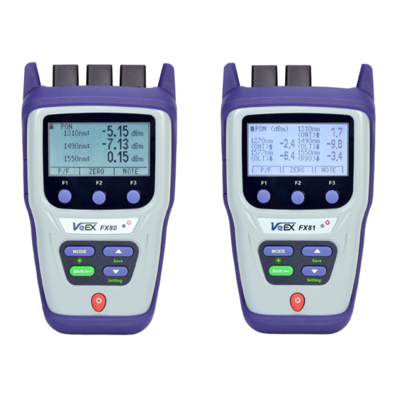
Colors, screen-labeled function keys, and screen fonts can vary with different device models and backlight settings. FX80/FX81 front view: FX80 with opt BB-OPM on left, FX81 5-wavelength version on the right |Power|: Turn device ON/OFF. Press and hold the button for 3 seconds. The VeEX logo, current date and time, and current mode of operation will be displayed. -
Page 8: Fx80/81 Test Ports
• VFL (optional): Use the 650 nm visual fault locator to visually locate breaks or excessive bends in fibers. [FX80 Only] The FX80 can be configured with either optional OPM or VFL, but not both. The FX81 can only be configured with optional BB-OPM with 4 wavelengths. -
Page 9: Getting Started
Getting Started Before using the FX80 or FX81 power meter for the first time, fully charge the battery and set the local date and time. The date and time is required to time-stamp the test results. Battery Charging The unit is equipped with a built-in, rechargeable Li-Polymer smart charge battery which is partially charged upon delivery. -
Page 10: Battery Replacement
Before saving measurement results for the first time, set the device date and time. To configure settings: 1. Power ON the FX80/FX81 by pressing and holding the |Power| button for 3 seconds. 2. Press |Shift/Enter|+|Down| to enter the Settings mode - the following parameters can be set: •... -
Page 11: Resetting Test Device
5. Press |Shift/Enter| to save the settings. Resetting Test Device To reset the FX80/FX81 power meter to factory default settings: 1. Disconnect the external power supply from the device. 2. With the device OFF, press and hold the red |Power| button for at least 15 seconds. -
Page 12: Optical Power Measurements
VeEX source is used. PON Power Measurements To use the FX80 or FX81 for PON measurements, connect the two fibers to the correct OLT and ONT test port. FX80/FX81 Top Panel, FX80 or FX81 (4-wavelength) with opt. BB OPM on the left, FX81 (5-wavelength) on the right For best results, wait 5 minutes after the FX80/81 is powered ON. -
Page 13: Setting Zero Level
6.2.1 Setting ZERO Level Set the ZERO level with the dust caps closed before first using the FX80/81 for PON power measurements. It is recommended to set the ZERO level prior to each new batch of measurements, or after measurement conditions have changed. -
Page 14: Creating User-Defined P/F Thresholds
Burst/PON or PON CW) to set the thresholds. PON/PON Burst is used in the figures below, but the GUI is identical. PON Burst mode, FX80 PON Burst mode, FX81 Page 14 of 50 FX80 / FX81 PON Optical Power Meters User Manual... - Page 15 5. Set the necessary value pressing |Up| and |Down|. 6. Confirm the value by pressing |Shift/Enter|. 7. Press |F1| (EXIT) to exit the Setting Pass/Fail thresholds mode. Page 15 of 50 FX80 / FX81 PON Optical Power Meters User Manual...
-
Page 16: Creating A Pass/Fail Threshold Profile For Measurements
The FX80/FX81 is now ready to measure PON levels and compare values against the Pass/Fail thresholds settings. The thresholds settings will remain active until changed. If the FX80/FX81 battery is allowed to fully discharge, all settings such as Pass/Fail and Device settings will return to original factory defaults. To retain Pass/Fail settings for future use, save them to a profile. -
Page 17: Thresholds Adhering To The Current 1G/10G Pon Standards
1490nm OLT Launch Power 1490 ONT/ONU Receive Power ODN Class Class A Class B Class C Class A Class B Class C Min Avg Power (dBm) Max Avg Power (dBm) Page 17 of 50 FX80 / FX81 PON Optical Power Meters User Manual... - Page 18 1310nm ONT/ONU Launch Power 1310 ONU Receive Power ODN Class Class A Class B Class C Class A Class B Class C Min Avg Power (dBm) Max Avg Power (dBm) Page 18 of 50 FX80 / FX81 PON Optical Power Meters User Manual...
- Page 19 Class N2 Class E1 Class E2 Class N1 Class N2 Class E1 Class E2 Min Avg Power -27.5 -29.5 -31.5 -33.5 (dBm) Max Avg Power -7.0 -9.0 (dBm) Page 19 of 50 FX80 / FX81 PON Optical Power Meters User Manual...
- Page 20 1310nm ONT/ONU Launch Power 1310nm OLT Receive Power OPL Class Class B+ Class C+ Class B+ Class C+ Min Avg -26.0 -30.0 Power (dBm) Max Avg -5.0 -9.0 Power (dBm) Page 20 of 50 FX80 / FX81 PON Optical Power Meters User Manual...
-
Page 21: Performing Optical Power Measurements In Pon
6.1. Modes for Optical Power Measurements for details. 2. To test a PON network, the FX80/FX81, in the figure above, must be connected at the OLT and ONT of the network. the following locations: OLT [location B or D], Fiber Distribution Hub/Point (FDP) [location A] or ONU/ONT [location C] are the possible respective test points. - Page 22 If PON network elements have SC/UPC connectors and the FX80/FX81 has SC/APC, two conversion patchcords are needed. When first testing at the FDP-A location, if there is no drop line installed, the 1310 nm upstream will be seen only if a fiber is temporarily connected to the ONT. This may require two patch cords.
- Page 23 If P/F thresholds have been set, the measurement results are presented as Pass or Fail (see the example below). PON Burst mode measurement results as P/F thresholds, FX80 Page 23 of 50 FX80 / FX81 PON Optical Power Meters User Manual...
- Page 24 PON Burst mode measurement results as P/F thresholds, FX81 To switch back to actual values for the same measurement, press the |F1| (P/F) button. Switching from thresholds to values for the same measurement, FX80 Page 24 of 50 FX80 / FX81 PON Optical Power Meters User Manual...
-
Page 25: Broadband Power Measurements (Optional For Fx80/Fx81 4-Wavelength Version)
OPM test port and press |MODE| until the PM1 or PM2 test mode appears at the upper left corner of the display. Page 25 of 50 FX80 / FX81 PON Optical Power Meters User Manual... - Page 26 The new wavelength then appears in the top right corner of the display. For the previous wavelength to remain effective, select a wavelength and then press the |F1| (EXIT) button. Page 26 of 50 FX80 / FX81 PON Optical Power Meters User Manual...
-
Page 27: Using Waveid
6.3.1 Using WaveID When paired with a compatible VeEX light source, the optical signal employs a proprietary WaveID which sets the OPM to the correct wavelength calibration setting. When [ AUTO] is set, the FX80/FX81 optional BB-OPM determines the wavelength automatically. -
Page 28: Setting Power Reference Level
The current reference level value is shown on the second row to the left (-6.86 dBm in the example below). [REF SET replaces REF FIX in later firmware versions] Current power value set as the reference level Page 28 of 50 FX80 / FX81 PON Optical Power Meters User Manual... -
Page 29: Visual Fault Locator (Vfl)
|Shift/Enter|. To exit without setting, press |F3| (EXIT). Broadband measurement taken against a reference level Visual Fault Locator (VFL) The FX80 can be equipped with a Visual Fault Locator (VFL). To test continuity: 1. Connect the fiber to the VFL port. - Page 30 Starting VFL testing, continuous light 4. To modulate the light (1 or 2 Hz), press |F2| (1Hz) or |F3| (2Hz), respectively. The pressed button then changes to continuous wave mode (CW). Page 30 of 50 FX80 / FX81 PON Optical Power Meters User Manual...
- Page 31 VFL testing, modulated light 5. To switch from the VFL mode to another mode, press the [MODE] button. Page 31 of 50 FX80 / FX81 PON Optical Power Meters User Manual...
-
Page 32: Viewing Measurement Results (Read Mode)
|F1| and |F2|. Viewing Measurement Results (Read mode) The FX80 can be optionally equipped with Bluetooth. If so, the Bluetooth sign appears in the top right corner in the Read mode. - Page 33 Once the note is saved with measurement results, it cannot be edited. Page 33 of 50 FX80 / FX81 PON Optical Power Meters User Manual...
-
Page 34: Downloading Test Results To A Pc
Downloading Test Results to a PC 1. To transfer test results and create a report, download and install LTSync PC software from the VeEX website. New users are required to register customer details and device information. 2. Upon entering login credentials, the website will flash and navigate to VeEX customer portal page. - Page 35 To install the USB driver: 1. Connect the VeEX power meter to the PC using a USB-A to micro-USB cable. 2. Launch Windows Device Manager and check for FX8x in the Other devices list. FX8x will be flagged with exclamation mark if the device driver is not installed.
- Page 36 Next. The driver installation begins, A new window appears when the driver has been updated successfully. The driver for FX8x successfully installed Page 36 of 50 FX80 / FX81 PON Optical Power Meters User Manual...
-
Page 37: Transferring Measurement Results To A Pc
PC. The figure below shows that a device is connected and the unique product ID. FX80 is connected to PC in LTSync, its serial number is recognized by the program Page 37 of 50... - Page 38 Use the scroll bar to view all results. For more information on using LTSync, see the LTSync User Manual at www.veexinc.com. FX80 Measurement results table Page 38 of 50 FX80 / FX81 PON Optical Power Meters User Manual...
- Page 39 Drag-and-drop this row to another group if needed. Alternatively, highlight the row, click the [Move row] button ( , see it, for example, in the Figure above), then highlight the desired group. Page 39 of 50 FX80 / FX81 PON Optical Power Meters User Manual...
-
Page 40: Transferring Measurement Results Via Bluetooth
To save the measurement results to a PC, click the [ Save to PC] button To erase all test results from the FX80/FX81 memory, select the Hardware tab and click the [ Erase all memory] button 8.2.2 Transferring Measurement Results via Bluetooth To transfer measurement results to the PC or mobile device via Bluetooth, the FX80/FX81 must be equipped with Bluetooth option. - Page 41 Read mode with Bluetooth 4. In LTSync, select the Hardware tab and click the Bluetooth button . The FX80/FX81 serial number appears in the [Connected to PC] field. If there are several devices connected to the PC via Bluetooth, select the desired device in the drop-down list.
-
Page 42: Uploading Measurement Results To Fiberizer Cloud
Fiberizer Main website registration window after clicking “Sign Up” If no Fiberizer Cloud account exists, click the [User Register in Fiberizer Cloud] button ( ), then register there. Page 42 of 50 FX80 / FX81 PON Optical Power Meters User Manual... - Page 43 Measurement results uploaded to Fiberizer Cloud To log out from the Fiberizer Cloud account, go to the Cloud storage tab and click the [Log out from Fiberizer Cloud] button ( Page 43 of 50 FX80 / FX81 PON Optical Power Meters User Manual...
-
Page 44: Uploading Measurement Results To Fiberizer Desktop Plus
The screenshots below show the procedure to upload measurement files to Fiberizer Desktop Plus repository window and generate PDF/Excel reports. Measurement results uploaded to Fiberizer Desktop Plus – File Upload Page 44 of 50 FX80 / FX81 PON Optical Power Meters User Manual... -
Page 45: Downloading Measurement Results To Fiberizer Mobile Olts (Fmolts) For Android
PDF/CSV Report Generation PDF Report Generated Downloading Measurement Results to Fiberizer Mobile OLTS (FMOLTS) for Android The Fiberizer Mobile OLTS Android app is available on Google Play and the VeEX Apps page at https://www.veexinc.com/Apps under Android devices. Page 45 of 50... - Page 46 Use the FMOLTS Android application to transfer test results from FX-4x and FX-8x series OPMs via Bluetooth or USB connection (using VeEX compatible OTG cable). The screenshots below show the procedure to transfer results from FX80/FX81 to the Android mobile device to be saved to mobile device’s storage and/or uploaded to Fiberizer Cloud.
- Page 47 Bluetooth device connection menu Bluetooth device pairing selection in app Page 47 of 50 FX80 / FX81 PON Optical Power Meters User Manual...
- Page 48 Test result shown on the main screen Downloaded FX81 results For more information, see the FMOLTS User Manual. Page 48 of 50 FX80 / FX81 PON Optical Power Meters User Manual...
-
Page 49: Certifications And Declarations
VeEX Inc. is committed to comply with RoHS and WEEE Directives to minimize the environmental impact of our products. For more information about RoHS as it relates to VeEX Inc, go to the VeEX web site at www.veexinc.com/ROHS. Page 49 of 50... -
Page 50: About Veex
VeEX Inc., a customer-oriented communications test and measurement company, develops innovative test and monitoring solutions for next generation telecommunication networks and services. With a blend of advanced technologies and vast technical expertise, VeEX products address all stages of network deployment, maintenance, field service turn-up, and integrate service verification features across copper, fiber optics, CATV/DOCSIS, mobile 4G/5G backhaul and fronthaul, next generation transport network, Fibre Channel, carrier &...
Need help?
Do you have a question about the FX80 and is the answer not in the manual?
Questions and answers