Table of Contents
Advertisement
Quick Links
Advertisement
Table of Contents

Related Manuals for VeEX VEPAL CX350S-D3.1


Summary of Contents for VeEX VEPAL CX350S-D3.1
- Page 1 CX350s-D3.1 e-Manual D07-00-102P RevA01 Page 1 of 109...
-
Page 2: Table Of Contents
CX350s-D3.1 e-Manual D07-00-102P RevA01 Page 2 of 109 Table of Contents 1.0 About this User Manual 2.0 Product Introduction 3.0 Safety Information 4.0 Basic Operation 4.1 Compact Platform Overview 4.2 Keypad 4.3 Touch-Screen Display 4.4 Battery 4.5 Connector Panels 4.5.1 Test Ports 4.5.2 Utility Ports 5.0 Home Screen and Menu 5.1 Screen Layout... - Page 3 CX350s-D3.1 e-Manual D07-00-102P RevA01 Page 3 of 109 7.4 Spectrum Analysis 7.4.1 Setup 7.4.2 Amplitude Measurements 7.4.3 Ingress Measurements 7.4.3.1 Forward Path Ingress 7.4.3.2 Reverse Path Ingress 7.5 Cable Modem 7.5.1 Setup 7.5.2 Cable Modem Results - DOCSIS 3.0 7.5.3 Cable Modem Results - DOCSIS 3.1/OFDM 7.6 Upstream Signal Generator (USG) 7.7 Installation Check 7.8 Advanced Tools...
- Page 4 CX350s-D3.1 e-Manual D07-00-102P RevA01 Page 4 of 109 8.1.1 Setup 8.1.2 IP Connection Status 8.1.3 Ping 8.1.4 Trace Route 8.2 NetWiz 8.2.1 Net Wiz Setup 8.2.2 Net Wiz Results 8.3 WiFiWiz 8.3.1 WiFi Procedure 8.4 Advanced 8.4.1 Fiber Scope 8.4.1.1 Automatic Focus Detection and Analysis 8.4.1.2 Main Advantages of Automatic Focus Detection 8.4.1.3 The Importance of Fiber Connector Inspection 8.4.1.4 Fiber Connectors and Test Gear Vulnerabilities...
- Page 5 9.8 Remote Access 10.0 File Management 10.1 File Manager: Working with Saved Results, Profiles, Images 11.0 Setup - Main Menu 12.0 ReVeal Software 13.0 Warranty and Software 14.0 Product Specification 15.0 Certification and Declarations 16.0 About VeEX Go back to top...
-
Page 6: About This User Manual
No part of this document may be reproduced or transmitted electronically or otherwise without written permission from VeEX Inc. This device uses software either developed by VeEX Inc or licensed by VeEX Inc from third parties and is the confidential and proprietary of VeEX Inc. -
Page 7: Product Introduction
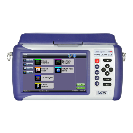
2.0 Product Introduction The VeEX™ VePal CX350s-D3.1 is a next generation test solution for analog and digital cable TV networks. The unit is a lightweight, rugged and weather resistant instrument featuring Analog and Digital signal level meter capabilities and is equipped with enhanced spectrum, forward and return path analysis functions. -
Page 8: Safety Information
Do not operate the instrument in the presence of flammable gases or fumes or any other combustible environment. VeEX Inc. assumes no liability for the customer's failure to comply with safety precautions and requirements. -
Page 9: Basic Operation
CX350s-D3.1 e-Manual D07-00-102P RevA01 Page 9 of 109 4.0 Basic Operation 4.1 Compact Platform Overview 4.2 Keypad 4.3 Touch-Screen Display 4.4 Battery 4.5 Connector Panels 4.5.1 Test Ports 4.5.2 Utility Ports 4.1 Compact Platform Overview Go back to top Go back to TOC 4.2 Keypad The keypad comprises the following keys: Power key: The unit is powered on and off from the red key on the keypad. -
Page 10: Touch-Screen Display
CX350s-D3.1 e-Manual D07-00-102P RevA01 Page 10 of 109 History key: The history key resets any blinking LED due to a history condition. Help key: The help key brings the user to the online help, regardless of the current user interface location of the unit. Lock key: Locks the keypad Home key: Bring the unit to its home menu regardless of its location on the user interface. - Page 11 CX350s-D3.1 e-Manual D07-00-102P RevA01 Page 11 of 109 Go back to top Go back to TOC 4.5 Connectors and Panels The connector panel located at the top of the unit comprises the following test ports (some are optional):...
-
Page 12: Test Ports
CX350s-D3.1 e-Manual D07-00-102P RevA01 Page 12 of 109 4.5.1 Test Ports Test Ports: To access the test connectors, please open the top cover. RF-in "F" Connector, 75 ohms for connection to the CATV network - Provides access to: Signal Level Meter (SLM) and associated functions Reverse Path QAM analyzer Note: Maximum Voltage input is 100VAC, 140VD Cable Modem:... - Page 13 CX350s-D3.1 e-Manual D07-00-102P RevA01 Page 13 of 109 Go back to top Go back to TOC...
-
Page 14: Home Screen And Menu
CX350s-D3.1 e-Manual D07-00-102P RevA01 Page 14 of 109 5.0 Home Screen and Menu 5.1 Screen Layout 5.2 Screen Icons 5.1 Screen Layout The Home menu can be accessed at anytime during operation by pressing the Home key on the rubber keypad. The screen is divided into three presentation areas: Left: 'V' Icon - Utilities Menu... -
Page 15: Screen Icons
CX350s-D3.1 e-Manual D07-00-102P RevA01 Page 15 of 109 Go back to top Go back to TOC 5.2 Screen Icons The following icons are displayed and located at the top of the screen: Power: Indicates if the unit is being powered by the internal Li-ion battery or external AC power. Tap the icon for battery status if running on battery. - Page 16 CX350s-D3.1 e-Manual D07-00-102P RevA01 Page 16 of 109 Go back to top Go back to TOC...
-
Page 17: Setup
CX350s-D3.1 e-Manual D07-00-102P RevA01 Page 17 of 109 6.0 Setup 6.1 Channel Tables and Locations 6.1.1 Channel Tables 6.1.2 Locations 6.1.3 Test Point Compensation Test mode, test port/s and network settings are required prior to performing any measurements or applications. Go back to top Go back to TOC 6.1 Channel Tables and Locations 6.1.1 Channel Tables... - Page 18 CX350s-D3.1 e-Manual D07-00-102P RevA01 Page 18 of 109 Channel Table Selection Channel Table Selection Select a table and press the Edit button Channel Table Editing...
- Page 19 CX350s-D3.1 e-Manual D07-00-102P RevA01 Page 19 of 109 Creating Channel Tables with ReVeal CX300 Alternatively, the channel tables can be created and managed using ReVeal CX300 PC software, which is a standard accessory. Additional tables can be created from a blank table or from existing templates. The test set and the PC software can exchange the tables for easy update.
- Page 20 CX350s-D3.1 e-Manual D07-00-102P RevA01 Page 20 of 109 Go back to top Go back to TOC 6.1.3 Test Point Compensation Test point compensation allows the loss at a certain test point to be automatically compensated. When performing a measurement, one of these preset test points can be selected by tapping the check box. The test set stores 10 sets of TP compensation value by name.
- Page 21 CX350s-D3.1 e-Manual D07-00-102P RevA01 Page 21 of 109 Go back to top Go back to TOC...
-
Page 22: Test Applications
7.0 Test Applications 7.1 Single Channel Measurement 7.1.1 Analog Channel Measurements 7.1.2 Digital Channel Measurements 7.1.3 Constellation Measurements 7.2 Tilt Analysis 7.3 System Scan 7.4 Spectrum Analysis 7.4.1 Setup 7.4.2 Amplitude Measurements 7.4.3 Ingress Measurements 7.4.3.1 Forward Path Ingress 7.4.3.2 Reverse Path Ingress 7.5 Cable Modem 7.5.1 Setup 7.5.2 Cable Modem Results - DOCSIS 3.0... - Page 23 Max Adjacent Channel in dB Carrier to Noise (C/N) in dB HUM in % Single Channel - Analog Results Note: The red blocks indicate the predefined threshold window for the measurement parameter. The effect of noise or poor C/N on analog video carriers is described below. Note: The average power changes depending on the picture content e.g.
- Page 24 CTB offset : 0 MHz CSO-3 offset: -0.75MHz CSO-4 offset: -1.25MHz The CX380S-D3.1 first measures the signal levels at those frequency offsets of a live carrier then prompts the user to either use a channel blocker or remove the carrier. The same frequency offsets will be measured after the carrier is removed or blocked and they are used to compare with the previously measured results with a live carrier to determine the final CSO/CTB values.
- Page 25 Note: Modulation Error Ratio (MER) In digital systems, MER is very similar to Carrier to Noise (C/N) in analog systems. MER measures how tightly symbols are recorded with respect to an optimum location based on the Error Vector Magnitude (EVM). Modulation Error Ratio (MER) and Error Vector Magnitude (EVM) Relationship MER determines how much margin the system has available before a failure can be expected.
- Page 26 to 256QAM, are more varied and critical than in the satellite domain. Constellation measurements are an example of such advanced measurements and are an ideal tool to identify QAM modulator problems. Note: QAM lock Ensure QAM lock is achieved on the digital carrier prior to making any Constellation measurement. Constellation button: The following measurements are reported: QAM Power Level (numeric in dBmV/dBuV)
- Page 27 The diagram is an X/Y plot of the I (In-phase) and Q (Quadrature) axis components of the QAM signal and is particularly useful for viewing impairments due to ingress and/or modulation problems present on the digital signal. A symbol (essentially a waveform representing one or more bits) should ideally appear as a compact or clean dot in the center of each symbol box.
- Page 28 System Noise - Incoherent Interference Coherent interference - CSO/CTB, spurs or ingress produce symbol clusters with a hole in the center so they appear as "donuts". This can also be a result of laser clipping or sweep interference. Coherent Interference Phase noise - Also known as Phase jitter in a QAM signal, it is caused by transponders in the transmission path or by the I/Q modulator.
- Page 29 Go back to top Go back to TOC 7.1.4 Impairment Measurements 7.1.4.1 Table Mode In addition to the standard digital carrier measurements, the following impairments are also measured with the optional Advanced Digital Measurement: Error Vector Magnitude (EVM) in % Measurement of modulation quality of the transmitted signal before forward error correction.
- Page 30 Go back to top Go back to TOC 7.1.4.2 Graph Mode The graph mode displays the Adaptive Equalizer Stress. The adaptive equalizer graph is a useful tool for troubleshooting linear distortion. Overview: Adaptive Equalization Modern Cable Modems, Set-top-boxes and Cable Modem Termination Systems (CMTS) use advanced Adaptive Equalizer technology to compensate for complex in-channel frequency response impairments caused by micro-reflections, amplitude ripple and group delay occurring in the cable network.
- Page 31 Go back to top Go back to TOC Equalized and Un-equalized MER measurements Un-equalized MER is typically measured before the adaptive equalizer, and equalized MER is measured after the adaptive equalizer, but often this circuitry resides in the QAM receiver and cannot be disabled. So while the adaptive equalizer does a great job of improving the MER of a QAM signal, it makes troubleshooting marginal amplifiers, small ingress, CPD and related impairments a lot more difficult.
- Page 32 7.1.5 Timed Stats For a Digital Channel, you can run a timed test, where key measurements are averaged over the designated test time. Press 'Timed Stats' and input the desired test duration. Press 'Start' to initiate the test. Timed Stats Go back to top Go back to TOC 7.2 Tilt Analysis Overview:...
- Page 33 Go back to top Go back to TOC 7.3 System Scan Overview: Within seconds, all analog and digital channels at the service location are measured. The function provides a graphical overview of the entire channel plan according to the selected active channel table. It can provide fast visual confirmation or a snapshot of key analog and digital TV channels or DOCSIS carrier levels.
- Page 34 Analog Channels Direct channel tuning and positioning of visual and audio carriers Visual and audio carrier level and frequency measurement Survey of system visual and aural carrier levels and frequencies Depth of modulation measurement Audio carrier FM deviation measurement Visual carrier-to-noise measurement In-channel response measurement Hum/low-frequency disturbance measurement Intermodulation distortion measurement (CTB and CSO)
- Page 35 boundaries. Start Frequency (MHz) and Stop Frequency (MHz) The CX380S-D3.1 allows the entry of Start and Stop frequency in place of the CF and Span. The entry mode can be changed by tapping on the CF or START icon. The entry range is from 5MHz to 1000MHz. Zero Span Zero Span mode is typically used for measuring the level variation of an analog channel.
- Page 36 The Burst QAM mode can be toggled on and off. Pre-AMP The CX380S-D3.1 has a built-in pre-amplifier. This amplifier is useful of detecting the noise floor in a return path. Peak Detector Can change the Peak Detector setting from 'Peak-Average' (default) to 'Positive-Peak'. 'Positive-Peak' is best suited for noise floor detection.
- Page 37 Spectrum Analysis - Digital Signal Go back to top Go back to TOC 7.4.2 Amplitude Measurements Overview: Analog and digital carriers are very different in terms of the signal content and distribution of power over the channel and therefore need to be measured differently.
- Page 38 but to measure the total power contained within the 6 or 8MHz carrier. This is similar to needing to measure the area within the signal (haystack) instead of its height only. Using this example, the power has to be measured within one channel or within a specific frequency range. Use caution when viewing digital modulated signals because the signal level is dependent on the selected measurement bandwidth (resolution bandwidth).
- Page 39 1. The "divide and conquer" method normally works best. Establish the most distant point from the headend at which the signal is known to be good quality. Start midway between this point and the affected subscribers to locate the problem amplifier 2.
- Page 40 Go back to top Go back to TOC 7.5.1 Setup The CX380S-D3.1 offers a built-in DOCSIS 3.1 cable modem as an option. The built-in cable modem is able to range, register and connect with the headend CMTS to obtain the necessary parameters and a valid IP address on the network. Launch the Cable Modem application to access the Setup screen.
- Page 41 Channel: input your system's primary DOCSIS channel DOCSIS Mode: DOCSIS 3.0: for DOCSIS 3.0 systems, with up to 32x8 Channel Bonding support. DOCSIS 3.1: optional, for DOCSIS 3.1 / OFDM systems Note: Legacy DOCSIS 2.0/1.x systems are not supported. Test Mode: Terminate: terminate mode Pass Through: emulating a stand-alone Cable Modem.
- Page 42 Cable Modem (CM) Connection Procedure and Training Sequence 1. CM scans the Downstream (DS) spectrum for a valid DOCSIS signal (either 64QAM or 256QAM). This can be a time consuming step if the CM is not on a channel. 2. CM demodulates the DOCSIS signal and looks for a SYNC message. 3.
- Page 43 Cable Modem, Ranging Tab, Online Status Go back to top Go back to TOC Server Connections DOCSIS specifies that for a system to become functional and operational, the CMTS and CM must interface with the following mandatory servers: Dynamic Host Configuration Protocol (DHCP) server - Defined by RFC2181, it provides the IP addresses for both the CM and subsequent PC devices that follow.
- Page 44 Cable Modem - IP Results Go back to top Go back to TOC Link tab: Provides information about the packets received, the downstream signal (frequency, modulation, level, MER) and about the upstream signal (frequency, level, modulation). Cable Modem - Link Results (Downstream) Cable Modem - Link Results (Upstream)
- Page 45 Go back to top Go back to TOC The Upstream channels provide Upstream Pre-Equalization information, which can be obtained by tapping on an Upstream UCD number. Press the Marker button to highlight a specific pre-equalizer coefficient, for advanced troubleshooting information. Cable Modem - Upstream Pre-Equalization Information Go back to top Go back to TOC Ping / Trace Route / VoIP / Web/ FTP tab:...
- Page 46 Go back to top Go back to TOC Pass Through tab: Provides the ability to emulate a real cable modem. In the Setup screen, select Pass Through for the Test Mode and press Connect. Once the Cable Modem goes online, connect a PC to the meter's 10/100/1000T RJ45 port at the top of the unit. Traffic will pass through the meter, which functions like an actual cable modem.
- Page 47 Go back to top Go back to TOC 7.5.3 Cable Modem Results - DOCSIS 3.1/OFDM Setup for DOCSIS 3.1/OFDM Systems For testing with DOCSIS 3.1 systems, follow these steps. 1. For a system that contains both Single Carrier QAM (SC-QAM) and OFDM channels, enter the primary SC-QAM DOCSIS Channel number and press Connect to go online.
- Page 48 Graphs tab, Online Status in D3.1 Mode D3.1 OFDM Tab Results OFDM Tab measurements: Level: reports Average, Maximum, and Minimum for the OFDM PLC. Frequency: Primary OFDM PLC Frequency...
- Page 49 Bandwidth: OFDM Channel Bandwidth MER (Avg): Average MER for the Active OFDM Subcarriers MER (Std Dev): Standard Deviation for the Active OFDM Subcarriers MER Percentile (2): the MER value for the worst 2% of all OFDM Subcarriers Subcarrier Bandwidth: bandwidth setting used for each OFDM Subcarrier Active Subcarriers: the number of active Subcarriers in the OFDM channel.
-
Page 50: Installation Check
Note: Symbol Rate The symbol rate is the gross bit rate, inclusive of channel coding overhead, divided by the number of bits transmitted in each symbol. Symbol rate is measured in symbols-per-second, hertz (Hz), or baud (Bd). The USG function is a powerful application to check and validate the reverse path for DOCSIS cable modem operation. The USG is used in conjunction with the QAM analyzer option. - Page 51 7.7.1 Setup The user can select to test Analog channels only, Digital channels only or both. OFDM channels can also be tested (requires OFDM option to be enabled). Installation Check Go back to top Go back to TOC 7.7.2 Results During the test, a status indicator is displayed.
-
Page 52: Advanced Tools
7.8 Advanced Tools Note: 1G / 10G Ethernet The test set supports optional single port 1 Gigabit and 10 Gigabit Ethernet test features. For more information, see the TX300s/TX320s User Manual on www.veexinc.com. Under the ADVANCED TOOLS menu, the following features are available: Return Path Analysis Sweep Operations MPEG Operations... - Page 53 For Return Path QAM analysis, the upstream signal source must be FEC encoded in order for MER, Pre-FEC, Post-FEC and Constellation analysis. Generally, a VeEX CX series test unit with USG+FEC is required as the signal source. To perform the Return Path QAM Analysis: 1.
- Page 54 Return Path Sweep: This function verifies the frequency response, tilt and proper operation of the amplifiers. Take a measurement by the sweep receiver in the Headend while sweep tones are inserted at point 2; the closest point to the Headend. Save this measurement as reference. Move and insert sweep tones at points 4, 5, 6, and 7, compare results and verify the frequency response and tilt at each point is relatively flat (refer to the graphic titled "HFC Test Points - Return Path"...
- Page 55 inserted into 6/8MHz channels for transmission over the HFC network to customer STBs. The key impairments that can occur are caused by micro-reflections, non-linearity problems in the network, and interference from adjacent analog channels (due to higher power levels). MPEG-2 QoS testing will occur at the Master satellite Headend, or at any other point where the Service Information is changed, and before insertion into the coaxial plant.
- Page 56 Always check signal level & quality of QAM carrier/s. Without a good strong signal, analysis of the MPEG stream may not yield any useful information. Check FEC counters and use Constellation diagram to identify problems. Disable/enable Equalizer to check QAM decoder performance, group delay and frequency response.
-
Page 57: Remote Operations
Go back to top Go back to TOC 7.8.4 Remote Operations... - Page 58 CW generator. The following functions are available under the Remote Operations menu: Remote View: An optional feature to allow remote viewing of other VeEX CX devices. IGM Scan Monitor: To view a CX180R-IGM, the return path monitor system, current scanning spectrum.
- Page 59 2. From the Remote View Setup page: For Responder Type, select CX180R. Select IP address of the CX180R-RPM system. Enter the IP port to be used by the CX380. Press Connect. Then, input the appropriate fields, such as 'Node ID' to connect to your CX180R-RPM System. 3.
- Page 60 CX380-Controller via Internet connection in real time. Enter the CX180R-IGM port number to be used and then return to the USG+FEC menu. For operations between CX380S-D3.1 and another CX380S-D3.1 unit: Remotely control another CX380S-D3.1 in responder mode for the following: Spectrum Analysis Return Path QAM Analysis Return Path Alignment with CW signal generated by USG...
- Page 61 Works with VeEX CX field meters Convenient internet connection via WiFi, Ethernet, Cable Modem, USB 3G data modem, USB Bluetooth with mobile phone dialing Automatic test results upload after each install GPS job location mapping Daily, weekly, monthly statistical analysis of job, technician and/or contractor performance...
- Page 62 7.8.8 HIP, Home Installation Process Contact Customer Care for more information about this feature. Go back to top Go back to TOC 7.8.9 Headend Check This optional features measures Analog and Digital channels as part of a single, detailed scan measurement. It tests all channels configured in the Channel Table.
- Page 63 FCC POP Digital POP1 Go back to top Go back to TOC 7.8.13 QAM Wiz DOCSIS Burst Demodulator The optional QAM Wiz DOCSIS Burst Demodulator helps identify rogue Cable Modems that contribute harmful interference to the plant. QAM Wiz does the following: - Captures all available Upstream Channel Descriptors provided by the CMTS from a specific downstream DOCSIS channel.
- Page 64 2. Input the CMTS DOCSIS Channel number and press 'Apply' QAM Wiz - Channel Input 3. Select the desired UCD and press 'Analyze' QAM Wiz - UCD...
- Page 65 4. The Burst Demodulator may take up to one minute to display results. Typically within 30 seconds, various Upstream measurements will be displayed. Press the "MAC List" to view associated Cable Modem MAC Addresses. MAC Addresses Go back to top Go back to TOC...
-
Page 66: Setup
CX350s-D3.1 e-Manual D07-00-102P RevA01 Page 61 of 109 8.0 Tools 8.1 IP Tools 8.1.1 Setup 8.1.2 IP Connection Status 8.1.3 Ping 8.1.4 Trace Route 8.1 IP Tools The 10/100BaseT management port is located on the right hand side of the unit. This port can be used to connect to the unit for management purposes (e.g., results retrieval, software upgrade, remote connectivity, etc). -
Page 67: Ip Connection Status
CX350s-D3.1 e-Manual D07-00-102P RevA01 Page 62 of 109 Subnet: Enter the subnet mask. Gateway and DNS: Enable or Disable. If set to enable, Gateway and DNS fields become available. Gateway: Off or On. IPv4 address of the network gateway. DNS: Off, Primary, or Primary & Secondary. If set to Primary or Primary & Secondary, a DNS IP is required in order to use the URL as a destination. - Page 68 CX350s-D3.1 e-Manual D07-00-102P RevA01 Page 63 of 109 Ping Testing Ping is a popular computer network tool used to test whether a particular host is reachable across an IP network. A ping is performed by sending an echo request or ICMP (Internet Control Message Protocol) to the echo response replies. Ping Setup Profile: Delete, Save, Save as..., or Default.
-
Page 69: Trace Route
CX350s-D3.1 e-Manual D07-00-102P RevA01 Page 64 of 109 Go back to top Go back to TOC 8.1.4 Trace Route Trace Route is a common method used to find the route to the destination IP address or URL. It is often used to identify routing problems and unreachable destinations. - Page 70 CX350s-D3.1 e-Manual D07-00-102P RevA01 Page 65 of 109 Trace Route Result Go back to top Go back to TOC...
-
Page 71: Netwiz
CX350s-D3.1 e-Manual D07-00-102P RevA01 Page 66 of 109 8.2 Net Wiz Net Wiz verifies the status of each IP address in the user selected range, by using ARP (Address Resolution Protocol) and ICMP test. 8.2.1 Net Wiz Setup Profile: Drop-down selections are Default, Delete, Save, Save As... Begin IP: Set the start address for the desired IP range using the numeric keypad End IP: Set the end address for the desired IP range using the numeric keypad Select the test by placing a check mark in the corresponding box of any of the following: ARP, Ping... - Page 72 CX350s-D3.1 e-Manual D07-00-102P RevA01 Page 67 of 109 The Devices tab reports global and detailed device information. Global reports: Total number of devices found Number of devices (Routers, Servers, Hosts) Net Wiz Results - Devices - Global Detail displays the Attribute, MAC and IP Addresses, and Ping test results of each device discovered. Net Wiz Results - Devices - Detail Go back to top Go back to TOC...
-
Page 73: Wifiwiz
Plug the WiFi adaptor into the USB port. Allow at least 30-45 seconds for the unit to detect the wireless adaptor and for the software driver to load. Note: Products support USB wireless adaptors supplied by VeEX only and have the necessary software driver built into the test set. - Page 74 CX350s-D3.1 e-Manual D07-00-102P RevA01 Page 69 of 109 SSID name of the AP BSSID (MAC address) of the AP 802.11 protocol version supported by the AP Max data rate supported by the AP AP's radio channel number Lock symbol indicates if security is set on the AP (WEP, WPA or WPA2). When the AP is unsecured, no lock symbol is displayed Signal strength of the AP Select one of the Access Points (AP) to start a connection.
- Page 75 CX350s-D3.1 e-Manual D07-00-102P RevA01 Page 70 of 109 Status The Status Tab displays the following information on the connection: Connection Status ESSiD: Name connected to BSSiD: MAC address of wireless router/device connected to Channel: WiFi Channel # connected to Encryption: Encryption type Mode Signal: Radio signal level (dBm)
- Page 76 CX350s-D3.1 e-Manual D07-00-102P RevA01 Page 71 of 109 Go back to top Go back to TOC...
-
Page 77: Fiber Scope
Cracks are not permitted in neither core nor cladding Equipped with 400x magnification, the VeEX Fiber Scope Inspector is well suited for general installation and maintenance checks on both single mode and multi mode fiber types. Contamination or damage that cannot be viewed at this magnification is unlikely to impact practical connector performance;... -
Page 78: Automatic Focus Detection And Analysis
Instead of adding the extra complexity, fragility, cost, size and weight of other electromechanical focusing systems currently available in the market, VeEX’s auto focus detection technology still relies on the incredible fast response and finesse of human hands, but leave the focus assessment, image capturing and analysis to the test set. Users could even try with their eyes closed and still achieve a perfectly focused image of the connector end-face in a few seconds. -
Page 79: Fiber Connector Inspection Setup
Interchangeable tips – Most commonly used tips are available (FC, SC, LC, ST, MTP, E2000, including PC, APC, 60° angled tips, among others) Compatible with VeEX test sets offering built-in Auto Focus-Detection & Analysis Ergonomic design Go back to top Go back to TOC 8.4.1.6 Fiber Connector Inspection Setup... -
Page 80: Captured Files Tab
CX350s-D3.1 e-Manual D07-00-102P RevA01 Page 75 of 109 image. Use the >Utilities >Files function to View the report, export to PDF format and copy to USB. MMF/SMF: Selects the type of connector/fiber to be analyzed and loads the correct Pass/Fail mask. Please note that the label in the button DOES NOT indicate the current mask type. - Page 81 CX350s-D3.1 e-Manual D07-00-102P RevA01 Page 76 of 109 Analyze: This soft button opens a more detailed analysis and report generation. Use the check boxes to select the images to be analyzed Image File: shows the name of the picture currently being displayed. Use the Open button to navigate, select and load any other file.
- Page 82 CX350s-D3.1 e-Manual D07-00-102P RevA01 Page 77 of 109 Results Table: Shows the defects and scratches count by sizes and position, used for the evaluation of the Pass/Fail criteria, according to the IEC 61300-3-35 standard. Go back to top Go back to TOC...
-
Page 83: Optical Power Meter (Opm)
CX350s-D3.1 e-Manual D07-00-102P RevA01 Page 78 of 109 8.4.2 Optical Power Meter (OPM) This function works in conjunction with Optical Power Meter dongles (USB), such the optional UPM-100. Insert the OPM dongle to on of the test set’s USB port before launching this application. Optical Power and Loss Measurements Wavelength: This pull-down menu provides a list of calibrated wavelengths to match the signal being measured. -
Page 84: Wifi Spectrum Analyzer
CX350s-D3.1 e-Manual D07-00-102P RevA01 Page 79 of 109 Power Limits (dBm): When check-box is ticked, users can enter the Minimum and Maximum power levels allowed for the application (e.g. in line with the transceiver’s dynamic range). If the power reading falls beyond those limits, the power measurement reading will turn red. - Page 85 CX350s-D3.1 e-Manual D07-00-102P RevA01 Page 80 of 109 Display Summary Planar view: Reports current, average, and maximum signal amplitude for each wireless frequency Topographic view: Emphasizes which frequencies are the busiest across the entire spectrum Spectral view: Historical view of wireless spectrum use at a point in time WiFi SA - Planar View Planar View Traditional Spectrum Analyzer view with Max, Average, and Current results...
- Page 86 CX350s-D3.1 e-Manual D07-00-102P RevA01 Page 81 of 109 Topographic View Similar to a density map - plots frequency versus amplitude Uses a special color scheme to assign colors to frequency amplitude points and to identify how often a particular coordinate is recorded Great resource for identifying devices with very low duty cycles Leaving it running will give a good indication of the typical local network conditions...
- Page 87 CX350s-D3.1 e-Manual D07-00-102P RevA01 Page 82 of 109 Signatures The Signatures button presets are available to identify unknown sources of RF activity (e.g., microwave oven) Select a device in the sidebar and click the pattern in the Topographic view to identify a device WiFi SA - Inspector Inspector The Inspector button setup allows the user to measure the frequency of the RF activity or interference of interest...
-
Page 88: Data Card
To establish an IP connection using a data card, please make sure that the data card is connected on the USB port. Note that only datacards provided by VeEX are supported and have the driver necessary for connection. The Data Card icon, as shown below, will appear at the bottom of the screen. - Page 89 CX350s-D3.1 e-Manual D07-00-102P RevA01 Page 84 of 109 Press the Dial Up key. In the IP Tools Setup menu, the Port will be displayed as "Datacard Port." The D for Data icon in the bar on the lower end of the screen will have a red cross to show that datacard is not connected - Select the configuration parameters, then press Connect.
-
Page 90: Wifi Inssider
When the AP is unsecured, no lock symbol is displayed Signal strength of the AP Access Points in the 5.0GHZ spectrum can only be displayed if the VeEX USB Wifi adapter supports 802.11a/n or 802.11 a/n/ac. Refer to the USB Wifi adapter specifications. - Page 91 CX350s-D3.1 e-Manual D07-00-102P RevA01 Page 86 of 109 5GHZ Channel 4. Tap the Graph tab of the respective Channel to view the results in a graphical presentation. Graph Use the Right/Left/Up/Down function keys or the arrow keys on the unit's keypad to navigate the graph and get additional information for the access points.
-
Page 92: Otdr Viewer
CX350s-D3.1 e-Manual D07-00-102P RevA01 Page 87 of 109 Go back to top Go back to TOC 8.4.6 OTDR Viewer This functionality allows the test platform to open and analyze standard OTDR .SOR files created by the TX300S-OTDR, RXT-4100 OTDR, FX300 OTDR or SunLite OTDR test sets. It can also be used to control the wireless OPX BOX OTDR via Bluetooth or USB connection, offering full-featured OTDR functionality. -
Page 93: Web Browser
The built in web browser uses the management port IP connection. An active IP connection can be established either through Ethernet, WiFi or datacard ports. The web browser defaults to VeEX's website. Use the Web browser's navigation bar to enter the name of the website you wish to reach. -
Page 94: Utilities
CX350s-D3.1 e-Manual D07-00-102P RevA01 Page 89 of 109 9.0 Utilities 9.1 Platform Settings 9.1.1 About 9.1.2 Screen Calibration 9.1.3 Bluetooth 9.1.4 Power 9.1.5 Backlight 9.1.6 Global Settings 9.1.7 Date and Time 9.1.8 Remote Access 9.1 Platform Settings This section provides settings for the global parameters of the test set or platform (system settings). Settings Menu Go back to top Go back to TOC 9.1.1 About... - Page 95 9.1.3 Bluetooth VeEX products support a micro USB Bluetooth adaptor offering wireless connectivity up to 10 meters (30 feet). Ultra compact and portable, the adaptor provides an untethered connection between the tester and other Bluetooth compatible devices such as a Notebook PC or cell phone, so the user can transfer test result files quickly and easily without having to hassle with memory sticks or Ethernet connections.
- Page 96 Bluetooth Adaptors - Compatibility Not all Bluetooth adaptors on the market are supported by the V300 product series. Please use adaptors that have been tested and supplied by VeEX only to ensure compatibility and correct operation. Go back to top Go back to TOC Bluetooth Setup Insert the Bluetooth adaptor into the USB port on the side of unit.
- Page 97 CX350s-D3.1 e-Manual D07-00-102P RevA01 Page 92 of 109 Bluetooth - Devices Tab Bluetooth - Connection - Passcode Go back to top Go back to TOC Setup Press Scan to check for available Bluetooth devices. Once scanning is complete, a list of discovered Bluetooth devices will be listed.
- Page 98 CX350s-D3.1 e-Manual D07-00-102P RevA01 Page 93 of 109 via Bluetooth and Mobile phone to a UMTS or 3G network, full data upload service will be required. Bluetooth - Connection Established Bluetooth - Connection Page 2 Go back to top Go back to TOC 9.1.4 Power This section provides information about current power source and information about the battery gauge.
- Page 99 CX350s-D3.1 e-Manual D07-00-102P RevA01 Page 94 of 109 Go back to top Go back to TOC 9.1.5 Backlight This section provides backlight control of the unit. Power: There are two settings -- one for Battery power and another for AC power. The user has the option to select a timer to turn off the backlight if the unit is not in use.
- Page 100 CX350s-D3.1 e-Manual D07-00-102P RevA01 Page 95 of 109 Brightness: The user can select the brightness level for Battery and AC operation modes. Backlight - Brightness Go back to top Go back to TOC 9.1.6 Global Settings General Setting Language: An alternative language for the user interface Units: Measurement system (English - feet or Metric - meter) Audible Alarm: When enabled, the test set's buzzer will sound (beep) when alarms and errors are being detected.
- Page 101 CX350s-D3.1 e-Manual D07-00-102P RevA01 Page 96 of 109 Storage Setting File Name Prefix: Tap on the box to enter the file name prefix using the pop up alphanumeric keypad Profile Deleting: Auto Delete or Prompt User Profile Saving: Auto Overwrite or Prompt User Result Saving: Manual or Prompt User Advanced Saving: On/Off.
- Page 102 PC: ReVeal PC software VNC Client Go back to top Go back to TOC ReVeal CX300 This VeEX application allows users to connect to the test set, using the platform’s IP address. ReVeal intuitive user interface offers the following functions:...
-
Page 103: Remote Access
CX350s-D3.1 e-Manual D07-00-102P RevA01 Page 98 of 109 Test Profiles Management: Create, Edit, upload and download complex Ethernet and Fibre Channel test profiles (BERT, Throughput, RFC2544, Y1564 SAM, Scan, IP, Ping/Trace, Packet Capture, etc) Test Results Management: Download results from the test set, manage local test results (PC HDD), generate detailed test reports, export to CSV or PDF, and print. - Page 104 CX350s-D3.1 e-Manual D07-00-102P RevA01 Page 99 of 109 VNC Viewer - Password Prompt Go back to 9.1.8 Remote Access Go back to top Go back to TOC...
-
Page 105: File Management
CX350s-D3.1 e-Manual D07-00-102P RevA01 Page 100 of 109 10.0 File Management V300 Style File Manager Go back to top Go back to TOC 10.1 File Manager: Working with Saved Results, Profiles, Images From Utilities go to >Files >Saved Displays all results stored in the test set Use the check box to select the desired files. - Page 106 CX350s-D3.1 e-Manual D07-00-102P RevA01 Page 101 of 109 Requires compatible USB dongle File Filters Makes it easier to isolate desired types of results from all other test results stored in the test set Reduces the number of pages displayed Activate Filters Use the stylus to tap on the Y+ icon Check mark the desired attributes Filters parameters can be combined...
-
Page 107: Setup - Main Menu
CX350s-D3.1 e-Manual D07-00-102P RevA01 Page 102 of 109 11.0 Setup - Main Menu This menu contains CX350s-D3.1 related system operation and parameter settings: Channel Table Default Location Tilt A&D Start Mode Choose whether the Tilt A&D Combined mode starts in Graph or Table mode. Unit To change the display unit between dBmV and dBuV. -
Page 108: Reveal Software
CX350s-D3.1 e-Manual D07-00-102P RevA01 Page 103 of 109 12.0 ReVeal Software For more information on using the ReVeal CX300 software, refer to the ReVeal CX300 PC Software for CX300 series User Manual at www.veexinc.com. Go back to top Go back to TOC... -
Page 109: Warranty And Software
Replace hardware which prove to be defective provided that the products that the customer elects to replace are returned to VeEX Inc. by the customer, along with Proof of Purchase, within thirty (30) days of the request by the customer, freight prepaid. -
Page 110: Product Specification
CX350s-D3.1 e-Manual D07-00-102P RevA01 Page 105 of 109 14.0 Product Specifications Note: Product Specifications The most recent product specifications can be downloaded from the VeEX website. For the most recent version, www.veexinc.com. Go back to top Go back to TOC... -
Page 111: Certification And Declarations
Use of this logo implies that the the unit conforms to requirements of European Union and European Free Trade Association (EFTA). EN61010-1 For a copy of the CE Declaration of Conformity relating to VeEX products, please contact VeEX customer service. -
Page 112: About Veex
Page 107 of 109 16.0 About VeEX VeEX, Inc., the Verification EXperts, is an innovative designer and manufacturer of test and measurement solutions addressing numerous technologies. Global presence through a worldwide distribution channel provides uncompromised product support. Visit us online at www.veexinc.com... - Page 113 CX350s-D3.1 e-Manual D07-00-102P RevA01 Page 108 of 109 RoHS Compliance - FAQ What is RoHS? RoHS is the acronym for Restriction of Hazardous Substances. Also known as Directive 2002/95/EC, it originated in the European Union and restricts the use of specific hazardous materials found in electrical and electronic products.
- Page 114 Our quality and environmental policy is to limit and progressively eliminate the use of hazardous substances and chemicals in the design and manufacture of our products. VeEX products are classified as Monitoring and Control Instruments under Article 2, Section (1), Category 9 of the WEEE 2002/96/EC Directive, and are therefore exempt to the RoHS requirements and restriction until 2010.
Need help?
Do you have a question about the VEPAL CX350S-D3.1 and is the answer not in the manual?
Questions and answers