Table of Contents
Advertisement
Quick Links
Advertisement
Table of Contents

Related Manuals for VeEX OTDR RXT-4113 Series


Summary of Contents for VeEX OTDR RXT-4113 Series
- Page 1 OTDR Series e-Manual, D07-00-076P-RevD00 Page 1 of 109...
-
Page 2: Table Of Contents
Table of Contents About This User Manual ................... 5 Product Introduction ....................6 (FX150/FX300/MTT /RXT/TX300 ) ..........6 LATFORM IGHLIGHTS PLUS ........................7 EATURES ....................... 8 ACKAGE ONTENTS Safety Information ..................... 9 Theory of Operation ....................10 OTDR ........................... 10 ........................ - Page 3 6.8.2 Connecting the Fiber Scope ....................... 41 6.8.3 Fiber Scope Setup ..........................42 6.8.4 Hardware and Software Settings ......................44 6.8.5 Capture Screen ............................. 45 6.8.6 Connector Face Analysis ........................46 6.8.7 Connector Face Analysis Results Table .................... 47 6.8.8 Result Files ............................
- Page 4 File Operations ........................... 102 7.10 ......................... 103 BOUT ReVeal Software ....................104 Warranty and Software ..................105 10.0 Product Specifications ..................107 11.0 Certifications and Declarations ................108 12.0 About VeEX ......................109 OTDR Series e-Manual, D07-00-076P-RevD00 Page 4 of 109...
-
Page 5: About This User Manual
VeEX, VePAL, Sunrise Telecom, Agizer, Optixsoft, Sunlite, Sunset, RXT, MTT, FX, TX, OPX, and Fiberizer are trademarks of VeEX, Inc. and/or its affiliates in the USA and certain other countries. All trademarks or registered trademarks are the property of their respective companies. -
Page 6: Product Introduction
Product Introduction The FX150, FX300, MTTplus, RXT, and TX300s feature an OTDR optimized for the installation and troubleshooting of FTTx, PON, CATV, Mobile Backhaul, and Metro fiber networks. Platform Highlights (FX150/FX300/MTTplus/RXT/TX300s) • Robust, compact hand-held design for demanding field test environments •... -
Page 7: Key Features
• RXT platform - 8400 mAH battery • Continuous operation of > 8 hours per Bellcore TRNWT-001138 (platform dependent) • ReVeal software to transfer fiber test data, upgrade software and perform remote control (check with factory on availability) • Fiberizer Cloud to upload fiber test data •... -
Page 8: Package Contents
Package Contents • OTDR (FX300, FX150, TX300S OTDR blade, RXT-4100 module or MTTplus-410 module) • AC/DC adaptor • Input: 100-240 VAC (50/60 Hz), 1.5A max (RXT1200/TX300S); 5.3A max (MTTplus); 1.5A max (FX150) • Output: 16VDC (RXT1200/TX300S); 15VDC (MTTplus); 12VDC (FX150) •... -
Page 9: Safety Information
Do not operate the instrument in the presence of flammable gases or fumes or any other combustible environment. VeEX Inc. assumes no liability for the customer's failure to comply with safety precautions and requirements. -
Page 10: Theory Of Operation
Theory of Operation OTDR The principle of OTDR operation is based on measuring the Rayleigh back scattering signal when a single powerful optical pulse passes through an optical fiber. The weak back scattering signal is registered by an optical receiver, converted into digital form and averaged many times. -
Page 11: Light Source
Light Source An optional light source is available and designed for generating continuous optical radiation. The light source output is the same as the OTDR port and uses the same laser diodes and optical splitter. The radiation power is stabilized with the help of external photodiode and power stabilization circuit. -
Page 12: Basic Operation
Basic Operation Test Ports and Interfaces OTDR testing: The optical fiber under test is connected to either the OTDR or OTDR-AUX (Filtered SM or MM) port on the top panel. The type of the optical fiber connector must correspond to the OTDR connector or adaptor type, including the connector polish. Optical Power Meter (OPM) testing: The optical fiber is connected to the OPM port on the top panel. - Page 13 TX300s Top View RxT-4100 OTDR Module OTDR Series e-Manual, D07-00-076P-RevD00 Page 13 of 109...
-
Page 14: Front Panel Layout
Front Panel Layout The picture below depicts the TX300s. Layout will vary depending on FX150, FX300, MTTplus, or RXT platforms. 5.2.1 LED Indicators Power/Charge LED - indicates battery charging is in progress. LED turns off when battery is fully charged. The device is powered from the built-in Li-Ion battery and can be operated with the AC/ DC adaptor plugged in. -
Page 15: Menu Navigation
• Save Trace/Result Key: Saves test result file (OTDR, OPM, Ethernet, Fiberscope - depends on active application and unit configuration) 5.2.3 Menu Navigation Navigate between test applications, setup menus, tabs, or active functions using the supplied stylus or by using up/down arrows followed by “Enter.” TX300s test unit: Getting started “Getting started”... -
Page 16: Mttplus Overview
MTTplus Overview 5.3.1 MTTplus Side View OTDR Series e-Manual, D07-00-076P-RevD00 Page 16 of 109... -
Page 17: Mttplus Control Panel
5.3.2 MTTplus Control Panel • Power: Press for 2 seconds to turn the test set ON or OFF (prevents accidental ON/OFF) If a test is running when the power off is started, test is terminated and results may not be automatically saved. •... -
Page 18: Rxt Overview
RXT Overview OTDR Series e-Manual, D07-00-076P-RevD00 Page 18 of 109... -
Page 19: Rxt Front Panel
5.4.1 RXT Front Panel • Power: Press for 2 seconds to turn the test set ON or OFF (prevents accidental ON/OFF) • Cursor Keys: Application dependent; May offer alternative GUI Navigation to touch screen (e.g. while wearing gloves in cold weather) •... -
Page 20: Getting Started
5.4.2 Getting Started A Quick Guide is always present in the Home screen after booting up (actual image may vary with models and software version) This screen can be displayed at any time from any screen. The test port group is assigned to the Fiber application when the MTTplus 410 or RXT-41xx OTDR module is installed. -
Page 21: Fx150 Overview
FX150 Overview FX150 Platform 5.5.1 FX150 Test Ports VFL/OPM/Aux-OTDR/OTDR-OLS 5.5.2 FX150 Keypad • Save: Saves the screen (bmp) • Power: Press for 2 seconds to turn the test set ON or OFF (prevents accidental ON/OFF) • Home: Resets user interface to Main menu OTDR Series e-Manual, D07-00-076P-RevD00 Page 21 of 109... -
Page 22: Fx150 Screen Navigation
5.5.3 FX150 Screen Navigation OTDR Screen Use the top tabs of the FX150 screen to access test measurement controls and view results. On the bottom bar, you can see: • IP address, when connected • Remote control connection status • Date and time •... -
Page 23: View/Hide Side Menu Panels
5.5.3.1 View/Hide side menu panels The left and right panels of the display provide icons to access key functions of the FX150. These panels can be turned on or off to enable a better view of the application screens. Use the shift keys located on the left and right sides of the unit to toggle on/off the left and right menu panels. -
Page 24: Setting Up Fx150 Wifi
5.5.4 Setting up FX150 WiFi The FX150 unit contains an optional built-in WiFi interface allowing you to easily transfer OTDR traces and upgrade software on the unit. 5.5.4.1 Access WiFi option 1. Press Utilities or the HOME key, and then press Bluetooth/WiFi. 2. -
Page 25: Connect To A Wifi Network
5.5.4.2 Connect to a WiFi network 1. Press Scan to see all networks 2. Select one of the available networks and the Edit Settings key will appear to the right. Once selected, an Edit Settings function key appears to the right. 3. -
Page 26: Customizing Your Tester
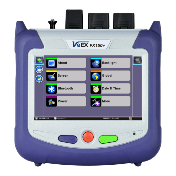
Customizing Your Tester You can customize the settings on your OTDR device in the Utilities>Settings menu. For additional information about setting up the unit, see the V150 Common Functions Manual on www.veexinc.com. Settings screen • About: Displays information about the software version, serial number, MAC address of the management port of the unit, as well as a list of software licenses (optional test features) currently loaded in the test set. - Page 27 Activating Touchscreen Calibration Mode You can activate the Touchscreen Calibration Mode using the keypad by pressing SAVE + HOME keys simultaneously for 3 seconds, then releasing. Press SAVE + HOME again to start a new calibration. • Backlight: User defined settings when unit is used on Battery or AC power including Brightness settings.
- Page 28 Host: Enables the micro USB port to connect with USB devices such as a USB stick or Fiberscope. USB devices will not be recognized if the OTG port is not set to Host mode. Device: Enables the micro USB port to connect directly with a Windows ...
-
Page 29: Test Fiber And Initial Preparation Introduction
Test Fiber and Initial Preparation Introduction Dirt, dust, and other contaminants severely impact high-speed data transmission in optical fibers and dirty connector end-faces are often the #1 cause of link failures. High insertion loss and/or high back reflection can result in transmission loss or high bit errors and poor BER. Furthermore, most measurement variations and test repeatability conditions in fiber-optic systems can be traced back to the cleanliness of optical connections. -
Page 30: Contamination
Contamination Optical connectors are susceptible to contamination from air borne particles and human body oils when exposed. Left over liquid residue from improper cleaning can also leave the fiber end face contaminated. The smaller the fiber core, the more severe the problem is likely to be, especially when you consider that fiber core diameters can range from 62.5 microns all the way down to 8 microns in size. -
Page 31: Cleaning Procedure
Cleaning Procedure To ensure proper and effective cleaning of optical fiber connectors and interfaces, please equip yourself with the following cleaning materials: • Isopropyl alcohol • Lint free soft tissues • Ferrule cleaners (1.25mm and 2.5mm versions) • Connector reel cleaners (CleTop or similar) Procedure 1. -
Page 32: Best Practices
Best Practices • Never touch the end face of an optical fiber connector with your hands or fingers. • Always install dust caps on unplugged fiber connectors. • Store unused dust caps in a re-sealable plastic bag to prevent dust accumulating. •... -
Page 33: Connectors
Connectors 6.5.1 Connector Types In fiber optic networks, you will come into contact with many different connector types, the most common being described below: ST Connector ST stands for Straight Tip-a quick release bayonet style connector developed by AT&T. STs were predominant in the late 80s and early 90s and are still one of the most commonly used fiber optic connectors in networking applications. - Page 34 LC Connector LC stands for Lucent Connector. It is a small form-factor fiber optic connector that uses a 1.25 mm ferrule, which is half the size of the ST / SC connectors. It uses a standard ceramic ferrule connector. The LC has good performance and is highly favored for both multimode and single mode applications, especially in high-density connector facilities.
-
Page 35: Connector Performance And Polishing
E2000 Connector Developed by Diamond, this connector has proven its performance worldwide in CATV and telecommunication networks. The connector features a spring-loaded shutter used to protect the ferrule from dust and scratches, and to provide increased safety protection. It uses a high precision Zirconia full ceramic ferrule with an insertion loss of 0.1dB. - Page 36 smooth surface. The main difference between UPC and PC is that the former has lower return loss. • Angled Physical Contact (APC) - The APC style produces the lowest return loss when compared to other styles. The ferrule is polished to an angle of 8 degrees. The angle is calculated so that it is less than the critical angle, which ensures light is not propagated back along the fiber.
-
Page 37: Fiber Cables And Fiber Patchcords
Fiber Cables and Fiber Patchcords 6.6.1 Fiber Cable Styles of Fiber Optic Cable vary in outer appearance, materials, application, features, and benefits. In OTDR applications, you will regularly come across the following types: Bare Fiber • Usually Spooled in 25km spools •... -
Page 38: Fiber Patchcord
2, 4, 6, 8, 12, 24, 48, 72, 144 or greater fiber counts • Outer Jacket can be of a variety of materials • Usually longer runs and can be terminated with almost any style of connector Ribbon • Commonly used in LAN and PON applications with MTP/MPO connectors 6.6.2 Fiber Patchcord A fiber patch cord is a piece of fiber cable that is used to connect the OTDR to the fiber under... - Page 39 Color Coding The buffer or jacket on patchcords is often color-coded to indicate the type of fiber used. Connector boot The strain relief “boot” that protects the fiber from bending at a connector is color-coded to indicate the type of connection. Connectors with a plastic shell (such as SC or E2000) typically use a color-coded shell.
-
Page 40: Inserting The Fiber
Inserting the Fiber Carefully align the optical fiber connector to the port to avoid rubbing the fiber against the external part of the port or any other surface. If the interface of the connector has an alignment key, make sure to insert it correctly into the corresponding groove. Push the connector in and make sure the optical cables are inserted to guarantee sufficient contact. -
Page 41: Fiber Scope Utility (Fx150, Fx300, Mttplus, Rxt-1200, Tx300S)
Fiber Scope Utility (FX150, FX300, MTTplus, RXT-1200, TX300S) 6.8.1 Fiber Scope Overview DI-1000 Digital Fiber Scope The DI-1000 uses auto focus to capture the image and grade the connector’s health and cleanliness after it is polished or cleaned. For more information about available connector tips, see the DI-1000 Digital Fiber Inspection Microscope Adapter Tips Guide on www.veexinc.com. -
Page 42: Fiber Scope Setup
Fiber Scope menu option 6.8.3 Fiber Scope Setup Fiber Scope Setup page 1 • Scope mode: Select Local (USB connect) or Remote (WiFi connect not available) operation. • Auto Save: Select Disabled, Enabled, Enabled+Report (pdf) or Enabled+V-Scout Report (l • Ask Before Save: Check this to be prompted to save after test is complete. OTDR Series e-Manual, D07-00-076P-RevD00 Page 42 of 109... - Page 43 The details entered in the following fields can be used to pre-set the filename automatically. and increment fiber or test number automatically. • Job ID, Cable ID, Fiber ID, Test ID (content in this field automatically added to filename) • Increment: Choose to increment by Fiber ID or Test ID (can be used to increment fiber count).
-
Page 44: Hardware And Software Settings
6.8.4 Hardware and Software Settings Check the settings for the Fiber Scope detected on the Info screen. Fiber Scope Info Screen OTDR Series e-Manual, D07-00-076P-RevD00 Page 44 of 109... -
Page 45: Capture Screen
6.8.5 Capture Screen Fiber Scope Capture Screen • Freeze / Resume: Stops the real time video so users can look at the static picture. • Analysis On / OFF: Turn the Auto Analysis ON and OFF (software option). • Auto Freeze: Turn ON and OFF the ability to freeze the image automatically, when in Focus. -
Page 46: Connector Face Analysis
To save the fiber picture on the screen, tap the screen. DI-1000 Fiber Scope When the DI-1000 Fiber Scope is plugged into USB, a blue LED will emit. The round FOCUS knob is on top. Turn right or left to focus. VS-500 Fiber Scope When the VS-500 Fiber Scope is plugged into USB, the white LED spotlight will automaticall turn ON. -
Page 47: Connector Face Analysis Results Table
6.8.7 Connector Face Analysis Results Table Analysis Results Table Select Page 2 of 2 view in the Capture tab. The test set displays a table with all numeric results from the analysis. Catalogs, Defect and Scratch events found for all four zones. Scratch requirements refer to width. -
Page 48: Result Files
6.8.8 Result Files Fiber Scope Analysis Result Files Select the file(s) by tapping them. • Load: Displays file for viewing. • Save: Saves file when autosave is disabled. Once saved, the files can be accessed in the File Manager or R-Server. For more information on File Manager, see 7.7.1 File Management. -
Page 49: Test Analysis Report
6.8.8.1 Test Analysis Report To view the report files, tap Utilities>Files>Save. The Fiber Scope test report can be viewed in JPG format or exported to PDF. In addition, all fiberoptic test results can be viewed using Fiberizer Cloud or Fiberizer DesktopPlus PC software. For more information on viewing reports, see 6.8.9 Managing Fiberscope Results with File Manager. - Page 50 Analysis Report (.pdf format) OTDR Series e-Manual, D07-00-076P-RevD00 Page 50 of 109...
-
Page 51: Managing Fiberscope Results With File Manager
6.8.9 Managing Fiberscope Results with File Manager 1. Go to Utilities >Files >Saved. All results stored in the test set are displayed. 2. Use the to select the desired files. 3. Tap on any column header to sort by that specific parameter (FS Analysis or Fiber Scope). Tap again to change the sorting order. -
Page 52: File Manager Filters
6.8.9.1 File Manager Filters File Filters make it easier to isolate desired types of results from all other test results stored in the test set. It also reduces the number of pages displayed. To activate filters, use the stylus to tap the + icon. Fiber inspection test results belong to Common Mode and Fiber Scope Tests. -
Page 53: Visual Fault Locator (Vfl)
Visual Fault Locator (VFL) The unit is equipped with an optionally built-in Visual Fault Locator (VFL) to trace and visually identify breaks in ODFs, bare fibers (900 µm), and patch cords that are typically hidden in the OTDR dead zone. The VFL works by injecting a 650nm visual red light into the fiber (up to 5 kilometers/3 miles) to bend a single fiber strand and force light to exit the center of the fiber. -
Page 54: Using The Vfl
6.9.1 Using the VFL To operate the VFL: 1. Make sure laser is turned off. Remove connector covers from the cable. 2. Connect the fiber to the VFL port located at the top of the unit. The VFL interface is fitted with universal 2.5mm sleeve accepting all 2.5 mm connector ferrules. -
Page 55: Optical Light Source (Ols)
5. Select the operation mode. CW: Continuous Wave. Select this option to turn on the VFL continually to check for faults. 1 Hz: Pulse. Select this option to send intermittent light pulses. In some cases, this makes it easier to identify faults (than continuous light). It can also be used with audible detectors (toners) that can identify faint light or in well-lit (bright) environments. -
Page 56: Accessing And Setting Up The Optical Light Source
6.10.1 Accessing and setting up the Optical Light Source To access and set up the OLS option: 1. Make sure that the Optical Light Source option is installed on the test unit. 2. Power on the unit. Test App 1 – Test Mode Selection is loaded by default. Select Fiber testing, and then press OK. -
Page 57: Using The Optical Light Source
5. Select the operation mode (CW, 270 Hz, 1000 Hz, or 2000 Hz) for the test. CW (Continuous Wave): Select to continually measure level, loss, and reflectance in optical components. 270 Hz, 1000 Hz, 2000 Hz (Pulse). Select this option to send intermittent light pulses. -
Page 58: Optical Power Meter (Opm)
On the test set display, view measurement loss in real-time. Note: Only optical power meters (e.g. Built-in, UPM-100 or FX40 series meters) approved by VeEX are supported. To see the most recent OPM specifications, go www.veexinc.com. Home icon to get to the Fiber Main Menu (OTDR, VFL, OLS, OPM test modes) -
Page 59: Configure The Opm
External OPM connection screen 4. Select the connected external meter and tap Connect. The OPM setup screen appears. If the test unit, also has a built-in meter that is preferable, tap Use Internal. 6.11.2 Configure the OPM When configuring the OPM, the meter must be referenced (calibrated) to the Laser Source output. -
Page 60: Opm Options
6.11.2.2 OPM options OPM (Optical Power Meter) options screen • Wavelength: List of calibrated wavelengths to match the signal being measured. • Wave ID: Detects the incoming wavelength automatically. Use when operating the OLS in CW mode with or without Loop enabled. •... -
Page 61: Using The Opm
• Zero: Recalibrates the OPM to zero value for when measurement conditions change significantly. When in doubt, perform this procedure prior to making any measurements. For example, when you are testing in cold outdoor temperatures and then move testing inside to a heated building. Put cover over OPM test port BEFORE recalibrating. -
Page 62: Table
6.12 Table To record individual readings, tap Acquire in the OPM tab. The readings appear in the Table tab. Table screen – Individual readings To save the individual results: 1. Select the checkbox next to the reading(s) to save, then tap Save. The Result saving screen appears. -
Page 63: Results
6.13 Results Results screen Use the following options when using the Results screen: • Push: Saves locally saved results to Fiberizer Cloud. See instructions for viewing and saving results below. • New: To create a new folder. • Save: Saves results. Once saved, the files can be accessed in the File Manager or R- Server (not available on all OTDR models). - Page 64 To view and save results using the FX150 meter: 1. On your device, select the results you wish to save, and then press Back. 2. To save locally, press Save. --OR— To push the results to Fiberizer Cloud, ensure connection to the network via Ethernet or WiFi, and then press Modify>Settings to sync with Fiberizer Cloud.
-
Page 65: Optical Loss Test Set (Olts) (Not Currently Supported)
6.14 Optical Loss Test Set (OLTS) (not currently supported) The unit’s OLTS option is used for end-to-end loss testing. It works by measuring a stable (reference) fiber first. The subsequent OLS test measurements are compared against the reference baseline to determine the end-to-end return losses. OTDR Series e-Manual, D07-00-076P-RevD00 Page 65 of 109... -
Page 66: Working With The Otdr
Working with the OTDR Test Setup (OTDR Setup page 1) Screens provided in this section are based on the V300 series OTDR. Slight differences may occur between FX150, FX300, MTTplus, or RXT platform screens when describing OTDR and OPM operation. 7.1.1 Initial Settings Wavelength: Select the wavelengths, which you wish to use to test the fiber. -
Page 67: Manual Mode
7.1.2 Manual mode To set test parameters manually, select Manual Mode. Manual Test Setup (page 1) Manual Test Setup (RxT-4111 only) OTDR Series e-Manual, D07-00-076P-RevD00 Page 67 of 109... -
Page 68: Test Parameters (All Otdr Models)
Manual Test Setup (RxT-4113 only) 7.1.2.1 Test Parameters (all OTDR models) • Mode: Manual, Auto, Manual Real Time, Auto Real Time, or V-Scout Profiles • Distance range (km, m, miles, kilofeet): maximum value of measured distances; the value of distance range should exceed the expected length of the fiber under test (20% more). - Page 69 Fiber Properties • Fiber Model: Select type of fiber to be tested to auto populate Index of Refraction (IoR) and Backscatter co-efficient (BS) values. • Wavelength (nm): Select desired wavelength for fiber properties. • Refractive index N: Setting for each available wavelength (also known as group index) is used to convert time to distance.
-
Page 70: Auto Mode
• Compensated Loss (dB): For OTDR with built-in internal launch fiber, (G.657), the OTDR connector insertion loss will depend on the fiber type connected to the test set. Mismatched fibers can result in higher panel loss than expected connector loss. Use the Span button to enter fiber mismatch compensation. -
Page 71: V-Scout Profiles (Optional)
• Front Panel Check – Report Insertion Loss and Reflectance and advise if acceptable or not. If testing PON or MUX, use a launch fiber between the OTDR and Splitter or MUX or disable this feature. • Span – See the Manual mode section for more information. •... - Page 72 2. In the Profile drop-down list box, select the V-Scout Profile configured previously or tap the V-Scout button to configure a new profile. The V-Scout Profiles screen appears. V-Scout Profiles Screen 3. Configure the V-Scout profile by using the information below. Tap OK to accept the changes selected or Abort to not accept the selections.
-
Page 73: V-Scout Link Map
To set up and use the automated V-Scout mode: 1. Select the Autosave parameters in the Setup tab. See the section Autosave Parameters for more details. 2. Tap the green Start button. Elapsed time and acquisition wavelength are indicated below the red Stop button. - Page 74 Modify: modifies LinkMap Type: Link Start, Link End, Subscriber Splitter, Connector, APC Connector, Splice, Macrobend, Office Splitter, Unknown Splitter Ratio: Not present, 1x2, 1x4, 1x8, 1x16, 1x32, 1x64, 1x128, 2x2, 2x4, 2x8, 2x16, 2x32, 2x64, or 2x128 Comments: Enter information regarding the modification. Information –...
- Page 75 7.1.4.3 V-Scout symbols The V-Scout Icons facilitate quick fiber diagnosis so that technicians can fix issues quickly and efficiently ensuring fast turnaround time and reduced truck rolls. The table below summarizes the symbols used to represent various events on the fiber link. Description Icon Span start (indicates start of analysis section) –...
-
Page 76: Thresholds (Otdr Setup
Thresholds (OTDR Setup page 2) Threshold settings are available on page 2 of the Setup tab. This allows you to preset and enable measurement thresholds. Events will be placed into the table only if the Analysis threshold is met/exceeded. Events that fail to meet the Pass/Threshold will be flagged and highlighted as red in the event table. -
Page 77: Pass/Fail Thresholds
• Distance Unit – Sets metric for distance between fiber sections in viewing window (km, kft, feet, meter, miles). • Splitters – Defines splitter loss values to be applied when building the LinkMap. Splitter Loss values 7.2.2 Pass/Fail Thresholds Events exceeding the Pass/Fail Thresholds are highlighted in Red in the Event table. Different Pass/Fail Thresholds values can be set for each test wavelength. -
Page 78: Autosave Parameters (Otdr Setup Page 3 And 4)
Autosave Parameters (OTDR Setup page 3 and 4) OTDR Setup page 3: Autosave • Auto Save: Select Disabled, Enabled, Enabled+Report or Enabled+V-Scout Report • Ask Before Save: Check this if you want to be prompted to save after measurement is completed The following information can be pre-set to create a name and increment fiber or trace number automatically (Page 3). - Page 79 The following information can be pre-set and automatically saved in the file (Page 4). • Originating location: where fiber starts • Terminating location: where fiber ends • Operator: name of operator • Comments: Add information about the fiber ends, comment about the result, status or any other meaningful information about connector, application, or case.
-
Page 80: Cloud Credentials (Otdr Setup
Utilities: File Management Cloud Credentials (OTDR Setup page 5) The user can register for a Cloud account: https://cloud.fiberizer.com. Setup page 5: Cloud Credentials After creating a Cloud Account, the user can then login and push test results into their account (Page 5 of Test Setup tab): •... -
Page 81: Making Measurements
Making Measurements Press Start and the measurement will begin according to the test parameters entered in the Setup menu (see 7.1 Test Setup (OTDR Setup page • The elapsed time is indicated on the red stop button on the right side of the display. The stop button will revert back to a green Start button when acquisition is complete. -
Page 82: Events
Events 7.6.1 Event Table The Events table is available in all measurement modes. Select the Events tab to display the trace with events. The Event table displays all events found during the analysis including those added manually by the user. Event Table (maximized) Event Table (RXT-4113) The Event table is displayed automatically when the Events tab is selected. -
Page 83: Event Types
Use Up/Down arrows to navigate the event table and to display or move to the highlighted event. Use the green left/right arrows to move the marker between the start and end of fiber being tested. To maximize the Event table, select the cross symbol again. 7.6.2 Event Types The Event is color coded depending on Threshold settings defined in the test setup (see... - Page 84 Deleting events: 1. Select the event in the Event table or by using the marker on the trace. 2. Use the left/right arrows to position the marker more accurately, if needed. 3. Once selected, press the Delete button on the right sidebar. The event will now be deleted from the event table and the event number will no longer appear on the trace.
-
Page 85: Measure Mode
Measure Mode There are several methods available to manually measure fiber characteristics. Prior to performing manual measurements, it is important you become familiar with the Markers and Zooming capabilities of the unit. 7.7.1 Markers Controls Markers are provided to measure distances accurately. Depending on measurement mode and viewing window, one or more markers are at the User’s disposal. -
Page 86: Zoom/Scroll Controls
7.7.2 Zoom/Scroll Controls Zooming operations are possible in both Events and Measure mode. Zoom Operations • Zoom/Scroll icon - Toggle between and enables Zoom/Scroll mode. • Zoom mode - Magnifying glass icon appears on screen. Draw a rectangular box over the trace with the stylus to create a zoom area. Visible part of the trace in Preview window is marked with dotted rectangle. -
Page 87: Distance Measurements
7.7.3 Distance Measurements Distance measurement – measure expanded trace view mode When a trace is displayed as show above, the fiber length is automatically measured from the start of the trace (or Span Begin) to each of the two markers and in between the markers. Proper marker placement is critical for accurate measurements. -
Page 88: Two Point Lsa (2-Pt Lsa)
than the level of Marker B and a positive loss measurement is displayed. If the loss value is reported as a negative quantity, it is termed a “gainer.” Measure loss between two points using the Loss (2-point) mode (using two markers): •... -
Page 89: Reflectance Measurement
4. Position center marker on the event’s rising or falling edge. You can use the rubber keypad to place the marker exactly, if needed. 5. Position the first two markers on a section of backscatter preceding the event and position the last two markers on a section of backscatter after the event ensuring that enough pre/post backscatter is used to make an accurate measurement. -
Page 90: Orl Measurement
7.7.7 ORL Measurement ORL is the total amount of light being reflected back towards the transmitter or source. This includes all backscatter and all reflections. The OTDR can calculate ORL from the fiber trace using the following procedure: 1. Make sure the Trace is active. 2. -
Page 91: Traces
Traces Select the Traces tab to view the active or measured OTDR traces. The color-coded blocks represent the corresponding trace viewed in the OTDR display. The OTDR can display up to ten traces simultaneously i.e. an active trace and nine additional traces. -
Page 92: Trace Properties
7.8.1 Trace Properties The traces in the memory are saved in BELLCORE, version 2.0 format. The OTDR trace files have the extension .sor which means Standard OTDR Record. These OTDR trace files can be opened by the software of other OTDR vendor applications provided the format is supported. - Page 93 Trace Information - Measurement • Thresholds: Analysis thresholds used to analyze the trace, as well as PON identification for LinkMap • Cables: Span Start and Span End information Trace Information - Cables OTDR Series e-Manual, D07-00-076P-RevD00 Page 93 of 109...
-
Page 94: Saving Otdr Traces
Span Begin and Span End Refer to section Launch/Receive fiber offset. The user can offset the length of an external launch fiber or patchcord, which is connected to the fiber under test; otherwise, it becomes part of the fiber span and analysis. The launch fiber can be offset or compensated in any of the following ways: •... -
Page 95: Saving Otdr Traces With Embedded Gps And Camera Image
7.8.3 Saving OTDR Traces with Embedded GPS and Camera Image 7.8.3.1 Obtaining GPS Coordinates To obtain the GPS coordinates for your current location: 1. Access Utilities>More>GPS/High Precision Clock. 2. Connect the antenna to the RF connector port (brass) located at the top of the unit. 3. -
Page 96: Adding Camera Image Otdr File (Mttplus Only)
7.8.5 Adding Camera Image OTDR file (MTTplus only) A Camera image can be added using the Manual Save only mode (AutoSave disabled) mode to display the Result AutoSaving pop up window. Enter all AutoSave field entries and select Generate PDF Report and/or select Add V-Scout Diagram. MTTplus Manual Save: Add camera image 1. - Page 97 MTTplus Manual Save: Image added to results OTDR Series e-Manual, D07-00-076P-RevD00 Page 97 of 109...
-
Page 98: Results
Results The Results tab displays the following information pertaining to OTDR traces. To expand the selection or folder directory, tap on the arrow. An arrow pointing to the right indicates the branch is collapsed whereas an arrow pointing downwards indicates the branch is expanded. The traces are saved in the following folder directory hierarchy: •... -
Page 99: File Management
Results tab: Wavelength/Trace 7.9.1 File Management File Location • Select Files/Saved menu to access saved traces or results • Use the stylus to select a file from the list. • Files types are as follows: • OTDR traces are saved as SOR files •... -
Page 100: Saving/Printing Traces To Pdf/Usb/Bluetooth
File Manager 7.9.2 Saving/Printing Traces to PDF/USB/Bluetooth Printing/Saving Result to PDF/USB/Bluetooth The saved OTDR sor file can be exported in several ways: • To save to PDF: • Use the Save as feature on Setup Page 3 and select Enable+Report (pdf) or Enabled+V-Scout+Report. - Page 101 • Saving to USB - exports saved file to USB memory device if plugged in. Each file is saved into its own folder using MyVeEX tree directory format. Use the Results View USB Export Flat feature if you want all files to be saved in the same folder. •...
-
Page 102: File Operations
7.9.3 File Operations In the File menu, you are able to delete or rename a selected result file or trace. File Operations Deleting Directories/Files 1. Select a directory or file from the list. 2. Press Delete icon at the bottom of the screen to remove a selected file from the memory. Renaming Directories/Files 1. -
Page 103: About Tab
7.10 About Tab About tab The following information is displayed in the About tab: • Developer name • OTDR firmware type • Firmware build • OTDR model • Platform serial # • OTDR wavelength/s OTDR Series e-Manual, D07-00-076P-RevD00 Page 103 of 109... -
Page 104: Reveal Software
ReVeal Software For more information on using the ReVeal software, refer to the ReVeal User Manual on the individual platform’s page at www.veexinc.com. OTDR Series e-Manual, D07-00-076P-RevD00 Page 104 of 109... -
Page 105: Warranty And Software
• Replace hardware which prove to be defective provided that the products that the customer elects to replace are returned to VeEX Inc. by the customer, along with Proof of Purchase, within thirty (30) days of the request by the customer, freight prepaid. - Page 106 • Damage due to software installed by the customer on the unit without prior authorization (written) from VeEX Inc. • Unauthorized alteration or misuse • Damage occurred from operating the unit outside of the environmental specifications for the product • Improper installation by the customer...
-
Page 107: Product Specifications
10.0 Product Specifications The most recent product specifications can be found on the VeEX web site at www.veexinc.com. OTDR Series e-Manual, D07-00-076P-RevD00 Page 107 of 109... -
Page 108: Certifications And Declarations
All applicable products imported into the EU market after July 1, 2006 must pass RoHS compliance. For more information about RoHS as it relates to VeEX Inc, go to the VeEX web site at www.veexinc.com. OTDR Series e-Manual, D07-00-076P-RevD00... -
Page 109: About Veex
VeEX Inc., an innovative, customer-focused communications test and measurement company, develops next-generation test and monitoring solutions for telecommunication networks and services. With a blend of advanced technologies and vast technical expertise, VeEX has developed products that diligently address all stages of network deployment, maintenance,...
Need help?
Do you have a question about the OTDR RXT-4113 Series and is the answer not in the manual?
Questions and answers