Table of Contents
Advertisement
Quick Links
INSTALLATION AND COMMISSIONING INSTRUCTIONS
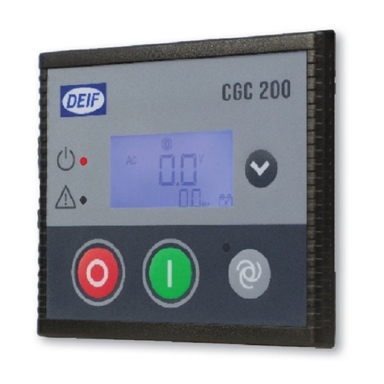
Compact Genset Controller, CGC 200
DEIF A/S · Frisenborgvej 33 · DK-7800 Skive · Tel.: +45 9614 9614 · Fax: +45 9614 9615 · info@deif.com · www.deif.com
● Mounting
● Terminals and wiring
● Commissioning, using the Utility
Software and/or the front panel
Document no.: 4189340806B
SW version:
Advertisement
Table of Contents

Subscribe to Our Youtube Channel
Related Manuals for Deif CGC 200


Summary of Contents for Deif CGC 200
- Page 1 Software and/or the front panel DEIF A/S · Frisenborgvej 33 · DK-7800 Skive · Tel.: +45 9614 9614 · Fax: +45 9614 9615 · info@deif.com · www.deif.com isenborgvej 33 · DK-7800 Skive · Tel.: +45 9614 9614 · Fax: +45 9614 9615 · info@deif.com · www.deif.com Document no.: 4189340806B...
- Page 2 CGC 200 installation and commissioning instructions 4189340806 UK 1. Introduction 1.1. About the Installation and commissioning instructions................3 1.1.1. General purpose ...........................3 1.1.2. Intended users ..........................3 1.1.3. Revision information ........................3 1.1.4. Software version ...........................3 1.1.5. Getting technical support.......................3 1.1.6. Other technical documentation......................3 1.2.
-
Page 3: About The Installation And Commissioning Instructions
The letter at the end of the document number on the front page indicates the revision number of this docu- ment. The latest version of this document can be downloaded at www.deif.com. If you click on the revision letter to the right of the document name, the revision history is displayed. -
Page 4: Warnings, Safety And Legal Information
CGC 200 installation and commissioning Introduction instructions 4189340806 UK ● Mounting ● Some technical specifications ● Data sheet ● Description, features, functions and approvals ● Layout and dimensions ● Terminals and wiring diagram ● Technical specifications ● Designer's handbook ●... -
Page 5: Factory Settings
CGC 200 installation and commissioning Introduction instructions 4189340806 UK DEIF does not recommend using the PC USB as the primary power supply for the CGC 200. The power drawn on start up exceeds the USB standard and may damage the PC. 1.2.3 Factory settings The controller is delivered pre-programmed from the factory with a set of factory settings. -
Page 6: Installation
CGC 200 installation and commissioning Installation instructions 4189340806 UK 2. Installation 2.1 Tools 2.1.1 Tools required The following tools are required to install the controller: Tool Used to Conducting wrist strap Prevent electrostatic discharge damage to controller Flat-bladed screwdriver with 3.2 mm (1/8") tip Tighten the mounting screw clamps (optional). -
Page 7: Wiring Diagram
CGC 200 installation and commissioning Installation instructions 4189340806 UK 2.2.2 Wiring diagram A wiring diagram for a typical installation is given below. Your system's wiring diagram may be different to the diagram given below, since a different configuration may have been chosen. - Page 8 2.2.4 List of terminal connections The power supply, inputs and outputs are connected to the CGC 200 terminals. CGC 200 also has a USB B- socket for connecting to a PC. The terminal connections are listed in the following table.
-
Page 9: Connecting The Terminals
CGC 200 installation and commissioning Installation instructions 4189340806 UK 2.2.5 Connecting the terminals The wiring is connected to the controller terminals using pull-apart PCB terminal blocks. For the MPU input, a magnetic head signal input and a shielding line are recommended. -
Page 10: Mounting Of The Unit
CGC 200 installation and commissioning Mounting instructions 4189340806 UK 3. Mounting 3.1 CGC 200 mounting Protect the controller terminals from static discharge during installation. 3.1.1 Mounting of the unit The unit is designed for mounting by means of two fixing clamps, which are included at delivery. - Page 11 4.1 Overview and parameter list 4.1.1 Sequence The sequence followed to commission the CGC 200 can be varied according to your needs. For example, you can upload the parameters from the utility software before mounting and wiring up the con- troller.
-
Page 12: Parameter List
CGC 200 installation and commissioning Commissioning instructions 4189340806 UK 4.1.3 Parameter list The parameters used by CGC 200 that can be changed from the controller front panel are listed in the table below. Param- Parameter Range Value Description eter name... - Page 13 CGC 200 installation and commissioning Commissioning instructions 4189340806 UK Param- Parameter Range Value Description eter name fault chos- num- value G RPM > 0 to 6000 1710 Generator over-speed protection, if run- ning detection (see P40) is RPM input only G f <...
- Page 14 CGC 200 installation and commissioning Commissioning instructions 4189340806 UK Param- Parameter Range Value Description eter name fault chos- num- value Running detect. 0 to 2 0: RPM 1: Genset frequency 2: RPM and frequency (running detec- tion is present when the value required...
- Page 15 CGC 200 installation and commissioning Commissioning instructions 4189340806 UK The parameters used by CGC 200 that can only be viewed and changed from the utility software are listed in the table below. Param- Parameter name Range Value Description eter fault...
-
Page 16: Checking The Wiring
4.2.1 Checking the wiring You can use the utility software during commissioning to check the wiring. You can connect the CGC 200 to a PC using a USB cable and check whether the operating values are as expected. You can use P43 and P44 to calibrate the genset and battery voltage measurements. - Page 17 CGC 200 installation and commissioning Commissioning instructions 4189340806 UK 3. Click Software download on the left side of the page. DEIF A/S Page 17 of 32...
- Page 18 CGC 200 installation and commissioning Commissioning instructions 4189340806 UK 4. Select Multi-line 2 Utility Software v.3.x. from the drop-down list. A dialogue box opens, with information about the most recent version of the software. DEIF A/S Page 18 of 32...
- Page 19 2. Use the suggested default settings. ● Note: Option N refers to a TCP/IP connection, and is not relevant for CGC 200. 3. When the installation is complete, there will be a Utility Software shortcut icon ( ) on your PC desktop.
- Page 20 200. The power drawn on start up exceeds the USB standard and may damage the PC. 1. Use the USB cable to connect the CGC 200 to the PC. The CGC 200 Power OK LED should light up. 2. If the Settings dialogue box does not open automatically, select File, then click Settings. Alternative- ly, press F3, or click the Settings icon ( ) on the toolbar.
- Page 21 CGC 200 installation and commissioning Commissioning instructions 4189340806 UK You must have a CGC 200 connected to your PC in order to see the Device, Alarms, Trending, Parameters and Inputs/Outputs pages. DEIF A/S Page 21 of 32...
- Page 22 The table below lists and describes the Utility Software pages. The pages are used to display and edit the controller information and settings. Page Name Description Device Overview for the connected CGC 200 Alarms Alarm history Trending Real-time trending of measured values Parameters...
-
Page 23: Parameters Page
CGC 200 installation and commissioning Commissioning instructions 4189340806 UK The table below lists and describes the most commonly used Utility Software icons. Commonly used icons Description Connect the device to the Utility Software Disconnect the device from the Utility Software... - Page 24 CGC 200 installation and commissioning Commissioning instructions 4189340806 UK Tree view In Tree view, the parameters are listed in groups, as shown below. Click on the group name to display all the parameters in that group. You can edit the parameters using the sliders, selectable text and values boxes. The parameter range and units are given (where applicable).
- Page 25 In List view, you can read and write all parameters from one table. The table headings are as follows: ● ParamID: Utility software identifier for the individual parameter ● LCDNumber: Parameter number on the CGC 200 LCD display ● Text: Parameter short description ● Unit: Unit of the parameter ●...
-
Page 26: Configuring Inputs And Outputs
CGC 200 installation and commissioning Commissioning instructions 4189340806 UK You must be in List view to set favourite parameters and write individual parameters. 4.3.5 Configuring inputs and outputs Digital inputs and outputs can be configured in either Tree or List view. - Page 27 Alternatively, click the value. A dialogue box opens where you can type in the value and click OK. 5. See Writing to the controller for information about how to write the changed values to the CGC 200. 4.3.7 Writing to the controller You can write to the controller by: ●...
- Page 28 Commissioning instructions 4189340806 UK If a CGC 200 file has been saved on the PC, it can be opened, edited and then written to one or more CGC 200s. To use the batch write function: 1. Click the batch read and write icon ( ) on the toolbar.
- Page 29 CGC 200 installation and commissioning Commissioning instructions 4189340806 UK 1. Press to increase the value of the digit where the cursor is blinking. You can use to de- crease the value. 2. Press to move to the next digit. 3. When the cursor is on the last digit, press to enter the access code.
-
Page 30: Abbreviations And Terms
Liquid Crystal Display The part of the front panel that displays icons and values. The icons and values displayed vary, depending on the CGC 200 mode and the operation of the equipment. Light Emitting Diode The controller front panel LEDs are used to show the genset status and alarms. - Page 31 National Electrical Manufacturers Association Oil Pressure Personal Computer The DEIF software must be run on a Windows PC, for example, a laptop computer. Root mean squared Refers to the average value of a sinusoidal wave. For example, V refers to the average AC voltage.
- Page 32 CGC 200 installation and commissioning Glossary instructions 4189340806 UK A value, or set point, used to determine the controller's operation. Parameters include alarm settings, and the configuration options for configurable inputs and outputs. The same set of parameters can be uploaded to several controllers.
Need help?
Do you have a question about the CGC 200 and is the answer not in the manual?
Questions and answers