Table of Contents
Advertisement
Quick Links
Advertisement
Table of Contents

Subscribe to Our Youtube Channel
Related Manuals for Deif iE 250


Summary of Contents for Deif iE 250
- Page 1 250 intelligent Energy controller Operator's manual...
-
Page 2: Table Of Contents
1. About the Operator's manual 1.1 Symbols and notation ..........................................1.2 Intended users of the Operator's manual ..................................1.3 Need more information? ......................................... 1.4 Software versions ............................................1.5 Warnings and safety ..........................................1.6 Legal information ............................................2. Getting started 2.1 About the display ............................................ - Page 3 3.8.2 Operator information messages .................................... 4. Configuration 4.1 Parameters page ............................................4.2 Input/output configuration ....................................... 4.2.1 About input or output channels ....................................4.2.2 I/O configuration page ........................................ 5. End-of-life 5.1 Disposal of waste electrical and electronic equipment ........................... Operator's manual 4189341349A EN Page 3 of 35...
-
Page 4: About The Operator's Manual
1. About the Operator's manual Symbols and notation Symbols for general notes NOTE This shows general information. More information This shows where you can find more information. Example This shows an example. How to ... This shows a link to a video for help and guidance. Symbols for hazard statements DANGER! This shows dangerous situations. -
Page 5: Intended Users Of The Operator's Manual
Self-help resources and how to contact DEIF for assistance. How to... Product Give feedback Learn how to use this product. iE 250 product page. Let us have your feedback on our documentation. AutoCAD 3D PDF AutoCAD drawing Step STP drawing... -
Page 6: Warnings And Safety
Software Details Version iE 250 Controller application 3.0.0.x PICUS PC software 1.0.21.x Warnings and safety Safety during installation and operation When you install and operate the equipment, you may have to work with dangerous currents and voltages. The installation must only be carried out by authorised personnel who understand the risks involved in working with electrical equipment. -
Page 7: Legal Information
This product contains open source software licensed under, for example, the GNU General Public License (GNU GPL) and GNU Lesser General Public License (GNU LGPL). The source code for this software can be obtained by contacting DEIF at support@deif.com. DEIF reserves the right to charge for the cost of the service. -
Page 8: Getting Started
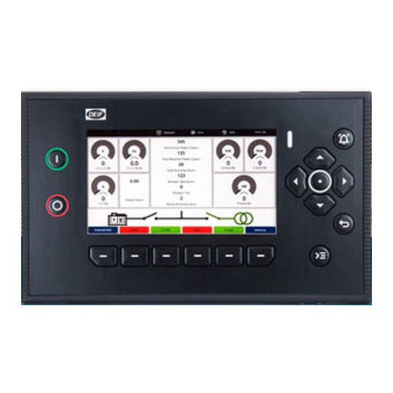
2. Getting started About the display 2.1.1 Display layout Item Notes Display screen 7" colour touch screen. Status LED Multi-colour LED for status indication. Silences the alarm horn relay, and opens the Notification centre, which shows alarms Notification centre and events. button Navigation buttons Up, down, left, and right arrows. -
Page 9: Screen Layout
2.1.2 Screen layout Island manual 80 % 10:18:38 Start attempts Total running hours 50.00 50.00 1795 Generator | L1-L2 Mains | L1-L2 Generator | L1 Mains | L1 Active energy export kvar kvar kvar Active energy export Generator | Total Generator | Total Mains | Total Mains | Total... -
Page 10: Controls
2.1.3 Controls You can operate the controller with flexible controls. 6-way navigation Button navigation for control, selection, and entering information. Touch screen Easy to use touch interface for most functions. This feature can also be disabled. Configurable buttons Six configurable buttons, allow direct functions from pages. Dedicated buttons Dedicated buttons for start and stop of the asset, Notification centre and Control centre. -
Page 11: Navigation Menu
2.1.4 Navigation menu To access the navigation menu, push the Back Island manual 364 h 80 % 10:18:38 Start attempts Dashboard Alarms Total running hours 50.00 50.00 Event logs 1795 Generator | L1-L2 Mains | L1-L2 Generator | L1 Mains | L1 Parameters IO configuration Active energy export... -
Page 12: Virtual Keyboards
2.1.6 Virtual keyboards The display has different virtual keyboards to enter information or settings. Some keyboards have unique features for the information that you are entering. The keyboards are designed for use by either button navigation or touch screen. Use either the touch screen or the navigation buttons to highlight, edit, and select information. -
Page 13: Filter
2.1.7 Filter On selected pages you can use a Filter on the list shown by a type of condition. For example, filter the list where it contains a specific word. Sort Filter Show rows where Type Value... Cancel Apply Item Notes Sort Change to Sort. -
Page 14: Sort
2.1.8 Sort On some pages you can use a Filter on the list shown by a sort type. For example, sort the list in descending order of time. Sort Filter Sort by Time Descending Cancel Apply Item Notes Filter Change to Filter. Sort by Select a category to sort the list. -
Page 15: About The Controller Operation
2.2.2 Power management control The iE 250 controllers make sure that required power is available and that the system is protected for typical applications. All controllers have the ability to operate in Power management control. To take full benefit of the Power management, the controllers must be set to AUTO (Automatic) mode. In AUTO mode, the Power management automatically starts and stops assets for the power requirements. -
Page 16: Control And Operation
3. Control and operation About the control and operation The iE 250 controllers contain all the functions needed to protect and control different types of equipment and their breaker(s). SINGLE genset controllers The SINGLE genset controllers protect and control a genset, and the genset breaker. SINGLE genset controllers can optionally include a mains connection with or without a mains breaker. -
Page 17: Controller Modes
Controller modes 3.2.1 About the controller mode The iE 250 controllers operate in a controller mode. This mode decides which actions may be taken or how the controller reacts to operational situations. Controller modes: • AUTO - Automatic mode ◦ The controller can automatically start, stop, connect, and disconnect the asset. The operator cannot start a sequence manually, unless the local control setting is enabled for the controller or section. -
Page 18: Asset Control
Asset control 3.3.1 Start the asset Mode Procedure The asset start is typically controlled automatically and the display control is not available. In a Power management system, if it calculates that more power is required, the controller automatically AUTO starts the asset, with the priority order. (Automatic) When the controller is in REMOTE mode, the asset start is based on a remote signal, for example, from a PLC. -
Page 19: Breaker Control
Breaker control 3.4.1 Close the breaker Mode Procedure The breaker close is controlled automatically and the display control is not available. In a Power management system, if it calculates that more power is required, the controller automatically AUTO starts the asset and closes the breaker, with the priority order. (Automatic) When the controller is in REMOTE mode, the breaker close is based on a remote signal, for example, from a PLC. -
Page 20: Alarms
Alarms 3.5.1 About the alarms The controller alarms prevent unwanted, damaging, or dangerous situations from occurring. The Operator must review all activated alarms for cause and suitable action. Each alarm has an Alarm condition which determines if the alarm is activated. When the Alarm condition is detected (typically, the operating value reaches the Set point), the controller starts the Time delay (t delay During the Time delay the controller checks whether the Alarm condition remains active:... -
Page 21: Alarm Flowchart
3.5.2 Alarm flowchart 1. The controller detects an Alarm condition. Start 2. The controller checks if the alarm is enabled: • If the alarm is not enabled the controller ignores the alarm. 3. The controller checks if the alarm has an active inhibit. •... -
Page 22: Alarm States
3.5.3 Alarm states Alarm Alarm Symbol Acknowledge Notes condition * action ** • An alarm condition occurred. • An alarm action is active. Active Active Unacknowledged • An alarm requires acknowledgement. • An alarm requires action to clear the alarm condition. •... -
Page 23: Alarms Page
250 Land SINGLE_GENSET 2023-06-19 07:40:08 UTC Warning iE 250 Land SINGLE_GENSET DEIF 2023-06-19 07:40:01 UTC Trip generator breaker and shutdown engine iE 250 Land SINGLE_GENSET 2023-06-19 07:40:01 UTC Block mains breaker iE 250 Land SINGLE_GENSET MB c 2023-06-19 07:39:00 UTC Warning... -
Page 24: Alarm Handling And Actions
3.5.5 Alarm handling and actions When alarms are activated in the system, they appear on the Alarms page and the Notification centre. The Notification centre provides quick access for some alarm handling. For more comprehensive alarm actions use the Alarms page. -
Page 25: Logs
Logs 3.6.1 About event logs The event log is a historical recorded list of all system and operator events. For example, the acknowledgement of an alarm, or connection of an asset. If an ECU has been configured with Fieldbus, you can additionally view the DM2 event log. The DM2 event logs are retrieved from the engine and the ECU must be powered up to get the information. -
Page 26: Event Logs Page
Command event 2023-06-22 11:08:57 No NTP server(s) connected Action 2023-06-22 10:40:08 GB closed 2023-06-22 07:40:01 Busbar voltage and frequency OK 2023-06-21 06:27:02 DEIF network redundancy broken Action 2023-06-19 09:39:40 Application initialised correctly Switch log Info Item Notes Event list The symbol shows recorded event. -
Page 27: Dm2 Logs Page
3.6.3 DM2 logs page Search... SPN DESCRIPTION FMI DESCRIPTION SPN NUMBER FMI NUMBER OCCURRENCES Engine speed Data valid But Above Normal... Engine oil pressure Current Below Normal Or Operational... Engine oil temperature Current Below Normal Or Operational... Engine coolant temperature Current Below Normal Or Operational... -
Page 28: Notification Centre
Alarms can be either Active or Historical. Active alarms are unacknowledged and Historical alarms are acknowledged. Alarms have an Alarm severity which is configured in the Advanced section of the Parameters configuration. The Alarm severity is shown colour-coded: DEIF network redundancy b... High Warning PCM clock battery failure Medium... -
Page 29: Operator Messages
Operator messages 3.8.1 Controller status texts The controller status texts are shown at the top of the display. The status text shown depends on the type of controller. Not all texts apply for all controller types. Status text * Description Cannot read controller status. - Page 30 ** Applicable to both MAINS controller and SINGLE genset with mains breaker. *** Only on MAINS controller with tie breaker. 3.8.2 Operator information messages During operation some operator information messages may be shown. The information shown depends on the type of controller.
- Page 31 Operator info Additional information TB close unblocked ** The Block TB close function is not active. TB open cancelled ** The TB open was cancelled by a TB close command. Start enable not activated The genset cannot start, because Start enable is not activated. Static synchronisation activated The digital input is activated.
- Page 32 4. Configuration Parameters page Search... Nominal settings Engine Running detection Generator Feedback type Busbar Engine ready Power transformer Regulators Delay Breakers Frequency running detection Local power management RPM running detection Power management rules System power management MPU setup Communication Oil pressure running detection Local Expand Expand...
- Page 33 Input/output configuration 4.2.1 About input or output channels The controller channels are configurable but depend on the controller type, parameters, functions and alarms available. Some hardware types support bi-directional channels, where you can configure if the channel is input or output. More information See the Technical specifications in the Data sheet...
- Page 34 4.2.2 I/O configuration page Search... MIO2.1 MIO2.1 52, 55 DO 40, 41 AO AVR output Output type Alarm Function 43, 44 AO GOV output Select function Clear Any latched alarm 46, 48 DO Status OK 46, 49 DO Any alarm 46, 50 DO Crank 46, 51 DO Run coil 52, 53 DO Breaker close...
- Page 35 WEEE. In Europe, local governments are responsible for facilities to receive WEEE. If you need more information on how to dispose of DEIF WEEE, please contact DEIF. Operator's manual 4189341349A EN...
Need help?
Do you have a question about the iE 250 and is the answer not in the manual?
Questions and answers