Table of Contents
Advertisement
Quick Links
OPERATOR'S MANUAL
Compact Genset Controller, CGC 200
● Push-buttons, LEDs and display
● Basic tasks
● Controller parameters
● Monitoring operating data
DEIF A/S · Frisenborgvej 33 · DK-7800 Skive · Tel.: +45 9614 9614 · Fax: +45 9614 9615 · info@deif.com · www.deif.com
Document no.: 4189340770A
SW version: 1.xx or later
Advertisement
Table of Contents

Subscribe to Our Youtube Channel
Related Manuals for Deif CGC 200


Summary of Contents for Deif CGC 200
- Page 1 ● Monitoring operating data DEIF A/S · Frisenborgvej 33 · DK-7800 Skive · Tel.: +45 9614 9614 · Fax: +45 9614 9615 · info@deif.com · www.deif.com isenborgvej 33 · DK-7800 Skive · Tel.: +45 9614 9614 · Fax: +45 9614 9615 · info@deif.com · www.deif.com Document no.: 4189340770A...
-
Page 2: Table Of Contents
CGC 200 Operator's manual 4189340770 1. Introduction 1.1. About the Operator's manual........................4 1.1.1. General purpose ...........................4 1.1.2. Intended users..........................4 1.1.3. Revision information ........................4 1.1.4. Software version ...........................4 1.1.5. Other technical documentation......................4 1.1.6. Getting technical support.......................5 1.2. Warnings, safety and legal information....................5 1.2.1. - Page 3 CGC 200 Operator's manual 4189340770 5.2.5. Parameters page.........................33 5.2.6. Inputs/Outputs page ........................35 5.3. Using the Utility Software........................35 5.3.1. Changing parameters........................35 5.3.2. Configuring inputs and outputs....................36 5.3.3. Reading from the controller......................37 5.3.4. Writing to the controller........................38 5.3.5. Firmware upgrade ........................39 6. Glossary 6.1.
-
Page 4: Introduction
The letter at the end of the document number on the front page indicates the revision number of this docu- ment. The latest version of this document can be downloaded at www.deif.com. If you click on the revision letter to the right of the document name, the revision history is displayed. -
Page 5: Getting Technical Support
● Training: You can ask for training. ● Support: You can call or email DEIF. DEIF offers 24-hour support. There may also be a local DEIF sub- sidiary. ● Service: DEIF engineers can help with design, commissioning, operating and optimisation. -
Page 6: Factory Settings
Touching the terminals could lead to injury or death. DEIF does not recommend using the PC USB as the primary power supply for the CGC 200. The power drawn on start up exceeds the USB standard and may damage the PC. -
Page 7: Front Panel, Push-Buttons, Leds And Display
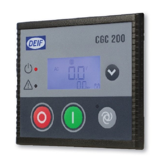
2. Front panel, push-buttons, LEDs and display 2.1 Front panel 2.1.1 Front panel drawing The drawing below shows the CGC 200 front panel. 2.2 Push-buttons 2.2.1 Push-button functions The push-buttons on the front panel have the following functions: Button... -
Page 8: Leds
The display (dimensions 20 mm x 40 mm) shows readings and alarms. Examples, with icons, in English, are given below. 2.4.2 Display views You can see the genset's measured values in the views on the CGC 200 LCD display. Press to scroll through the views. -
Page 9: Alarms
CGC 200 Operator's manual 4189340770 Front panel, push-buttons, LEDs and display Example: Battery DC voltage and genset running speed (RPM) Example: Battery DC voltage and total genset running hours 2.4.3 Alarms If an alarm is activated, it is shown on the screen by the alarm icon. See the examples below. -
Page 10: General Icons
CGC 200 Operator's manual 4189340770 Front panel, push-buttons, LEDs and display 2.4.4 General icons The general icons are listed in the table below. General icons Description Auto mode Stop mode Manual mode Generator voltage indication Battery voltage indication Speed unit (revolutions per minute) -
Page 11: Alarm Icons
CGC 200 Operator's manual 4189340770 Front panel, push-buttons, LEDs and display 2.4.5 Alarm icons The table below lists the CGC 200 display alarms icons, along with their descriptions. Alarm icons Description High temperature Low oil pressure Over-speed Under-speed Emergency stop... -
Page 12: Using The Controller
CGC 200 Operator's manual 4189340770 Using the controller 3. Using the controller 3.1 Genset control mode and status 3.1.1 Genset control mode There are three possible genset control modes: ● Manual: The genset is started and stopped by pressing the push-buttons on the front panel. -
Page 13: Viewing Alarms
CGC 200 Operator's manual 4189340770 Using the controller 3.2.4 Viewing alarms LED flashes when there is an alarm condition. You can see which alarm is present by looking at the icons on the display. 3.2.5 Resetting alarms To reset the alarms if there is a shutdown alarm, press 3.2.6 Stopping the genset... -
Page 14: Parameters
CGC 200 Operator's manual 4189340770 Parameters 4. Parameters 4.1 Changing parameters 4.1.1 Warning about changing parameters Be very careful about changing the controller parameters. Changing the controller parameters may affect the genset protections and performance. The controller parameters are set during the design. These parameters may be adjusted if necessary during commissioning. -
Page 15: Parameter List
CGC 200 Operator's manual 4189340770 Parameters 4.1.2 Parameter list The parameters used by CGC 200 that can be changed from the controller front panel are listed in the table below. Param- Parameter Range Value Description eter name fault chos- num-... - Page 16 CGC 200 Operator's manual 4189340770 Parameters Param- Parameter Range Value Description eter name fault chos- num- value G RPM > 0 to 6000 1710 Generator over-speed protection, if run- ning detection (see P40) is RPM input only G f <...
- Page 17 CGC 200 Operator's manual 4189340770 Parameters Param- Parameter Range Value Description eter name fault chos- num- value Running detect. 0 to 2 0: RPM 1: Genset frequency 2: RPM and frequency (running detec- tion is present when the value required...
- Page 18 CGC 200 Operator's manual 4189340770 Parameters The parameters used by CGC 200 that can only be viewed and changed from the utility software are listed in the table below. Param- Parameter name Range Value Description eter fault chos- number value...
-
Page 19: Changing Parameters Using The Front Panel
2. The access code screen opens. The four-digit access code prevents unauthorised people from changing the CGC 200 setup via the front buttons. The factory default code is 2000. To enter the access code: 1. Press to increase the value of the digit where the cursor is blinking. - Page 20 CGC 200 Operator's manual 4189340770 Parameters Button Description Function OFF and PAGE DOWN together Enter parameter setting mode AUTO Increase value, or next parameter Decrease value, or previous parameter PAGE DOWN Next, or Enter Exit DEIF A/S Page 20 of 43...
-
Page 21: Using The Utility Software
If you have this problem, you need to find the correct USB driver in the software installation folder and install it. The USW is normally downloaded from DEIF via the internet. To download the Utility Software: 1. Open www.deif.com in a browser. - Page 22 CGC 200 Operator's manual 4189340770 Using the Utility Software 3. Click Software download on the left side of the page. DEIF A/S Page 22 of 43...
- Page 23 CGC 200 Operator's manual 4189340770 Using the Utility Software 4. Select Multi-line 2 Utility Software v.3.x. from the drop-down list. A dialogue box opens, with information about the most recent version of the software. DEIF A/S Page 23 of 43...
-
Page 24: Starting The Utility Software
2. Use the suggested default settings. ● Note: Option N refers to a TCP/IP connection, and is not relevant for CGC 200. 3. When the installation is complete, there will be a Utility Software shortcut icon ( ) on your PC desktop. - Page 25 200. The power drawn on start up exceeds the USB standard and may damage the PC. 1. Use the USB cable to connect the CGC 200 to the PC. The CGC 200 Power OK LED should light up. 2. If the Settings dialogue box does not open automatically, select File, then click Settings. Alternative- ly, press F3, or click the Settings icon ( ) on the toolbar.
- Page 26 CGC 200 Operator's manual 4189340770 Using the Utility Software You must have a CGC 200 connected to your PC in order to see the Device, Alarms, Trending, Parameters and Inputs/Outputs pages. DEIF A/S Page 26 of 43...
-
Page 27: Utility Software Overview
The table below lists and describes the Utility Software pages. The pages are used to display and edit the controller information and settings. Page Name Description Device Overview for the connected CGC 200 Alarms Alarm history Trending Real-time trending of measured values Parameters... - Page 28 CGC 200 Operator's manual 4189340770 Using the Utility Software The table below lists and describes the most commonly used Utility Software icons. Commonly used icons Description Connect the device to the Utility Software Disconnect the device from the Utility Software...
-
Page 29: Device Page
CGC 200 Operator's manual 4189340770 Using the Utility Software 5.2.2 Device page The Device page is shown after successful connection with the controller. The following information is shown: ● Engine speed (RPM) ● Generator voltage ● Generator frequency ● Battery voltage ●... -
Page 30: Alarms Page
CGC 200 Operator's manual 4189340770 Using the Utility Software 5.2.3 Alarms page You can see the alarm history, with text, a time stamp and the status for each alarm on the Alarms page. See the following screenshot for an example. - Page 31 CGC 200 Operator's manual 4189340770 Using the Utility Software To start real-time trends: 1. Open the Trending page. DEIF A/S Page 31 of 43...
- Page 32 CGC 200 Operator's manual 4189340770 Using the Utility Software 2. Click the icon to select the measured values you would like to see on the trend, and click OK. An example is shown below. 3. To set how often the trend updates, as well as the trend width and memory, select File, then Settings, then the Trending tab.
-
Page 33: Parameters Page
CGC 200 Operator's manual 4189340770 Using the Utility Software 5.2.5 Parameters page You can read and edit parameters in either tree view (the default) or list view. Select the radio button at the top of the Parameter page to choose the view that you want. - Page 34 In List view, you can read and write all parameters from one table. The table headings are as follows: ● ParamID: Utility software identifier for the individual parameter ● LCDNumber: Parameter number on the CGC 200 LCD display ● Text: Parameter short description ● Unit: Unit of the parameter ●...
-
Page 35: Inputs/Outputs Page
CGC 200 Operator's manual 4189340770 Using the Utility Software You must be in List view to set favourite parameters and write individual parameters. 5.2.6 Inputs/Outputs page The status of inputs and outputs can be monitored on the Inputs/Outputs page. An example is shown below. -
Page 36: Configuring Inputs And Outputs
Alternatively, click the value. A dialogue box opens where you can type in the value and click OK. 5. See Writing to the controller for information about how to write the changed values to the CGC 200. 5.3.2 Configuring inputs and outputs Digital inputs and outputs can be configured in either Tree or List view. -
Page 37: Reading From The Controller
5.3.3 Reading from the controller Parameters, logs and the input and output configuration are stored in the CGC 200. This information can also be stored in a file on the PC. -
Page 38: Writing To The Controller
3. A window opens. Browse to the location where you would like to save the file, type in the name, and click Save 4. The parameters and input and output configuration may be changed, and written to the CGC 200. Alter- natively, the parameters can be saved to a file on the PC. See Writing to the controller for more infor- mation. -
Page 39: Firmware Upgrade
Restoring the controller information from a .bak file, using Restore Device. Batch write function If a CGC 200 file has been saved on the PC, it can be opened, edited and then written to one or more CGC 200s. To use the batch write function: 1. - Page 40 CGC 200 Operator's manual 4189340770 Using the Utility Software 1. Click the firmware upgrade icon ( ) on the toolbar. A window will open. 2. Browse to the firmware file you want to use. 3. Click Open. Do not disconnect the power supply or the USB cable during the firmware upgrade. Interrupt- ing a firmware upgrade can make the controller unusable.
-
Page 41: Glossary
Liquid Crystal Display The part of the front panel that displays icons and values. The icons and values displayed vary, depending on the CGC 200 mode and the operation of the equipment. Light Emitting Diode The controller front panel LEDs are used to show the genset status and alarms. -
Page 42: Terms
National Electrical Manufacturers Association Oil Pressure Personal Computer The DEIF software must be run on a Windows PC, for example, a laptop computer. Root mean squared Refers to the average value of a sinusoidal wave. For example, V refers to the average AC voltage. -
Page 43: Units
CGC 200 Operator's manual 4189340770 Glossary A value, or set point, used to determine the controller's operation. Parameters include alarm settings, and the configuration options for configurable inputs and outputs. The same set of parameters can be uploaded to several controllers.
Need help?
Do you have a question about the CGC 200 and is the answer not in the manual?
Questions and answers