
Related Manuals for IEI Technology prox.pad


Summary of Contents for IEI Technology prox.pad
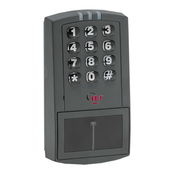
- Page 1 IEI prox.pad Proximity Reader/Keypad Access Control Installation/Programming Manual Document # 6055676, Rev 2.2, D4b...
-
Page 2: Table Of Contents
1.14.2 Gang Box and Mounting....................14 1.14.3 Mounting the Unit on Metal....................14 1.14.4 RF Interference .........................14 1.15 Checking the Cables.........................15 1.16 Mounting the prox.pad Unit.......................19 1.16.1 Performing a Wall Mounted Installation................19 1.16.2 Performing a Glass Mounted Installation................20 1.16.3 Performing a Secure Installation..................21 1.16.4 Installing a Tamper... - Page 3 Installation/Programming Manual 2.7.1 General Programming Features..................35 2.7.1.a Changing the Master Code...................35 2.7.1.b prox.pad Default Settings.....................36 2.7.1.c prox.pad LED Indicators/Sounder Operations – Standalone Mode......37 2.7.2 Programming Users......................38 2.7.2.a User Types........................38 2.7.2.b Programming a “Code Only” User................38 2.7.2.c Programming “Card Only” Users by Presentation............39...
- Page 4 Installation/Programming Manual 3.3 Wiegand Front End Programming....................61 3.3.1 Entering Program Mode.......................61 3.3.2 Changing the Master Code....................61 3.3.3 Enabling Wiegand Front End Mode..................62 3.3.4 Wiegand Keypad Data......................62 3.3.5 Programming the Facility Code for Wiegand Keypad Data..........62 3.3.6 Card Data..........................62 3.3.7 Enabling/Disabling Audio Keypress Feedback..............63...
- Page 5 Installation/Programming Manual 5.5.2 Wire Run..........................85 5.5.3 Lithium Battery Replacement....................85 Document # 6055676, Rev 2.2, D4b Page 5 of 86...
- Page 6 Table 8: Standalone Programming Commands..................56 Table 9: prox.pad LED Indicators/Sounder – Wiegand Mode...............68 Table 10: Wiegand Programming Commands..................69 Table 11: prox.pad LED Indicators/Sounder Operations – Secured Series Mode.......71 Table 12: Secured Series Front End Programming Commands............79 Table 13: Troubleshooting Chart......................81 Page 6 of 86 Document # 6055676, Rev 2.2, D4b...
- Page 7 Figure 14: Electric Strike (Fail Secure) Wiring..................33 Figure 15: MagLock (Fail Safe) Wiring Diagram...................33 Figure 16: Wiring to a Wiegand Panel....................60 Figure 17: Wiring the prox.pad to the Secured Series DCM..............70 Document # 6055676, Rev 2.2, D4b Page 7 of 86...
-
Page 8: Chapter 1: Introduction/Installation
Chapter 1: Introduction/Installation About this Manual This manual is designed for installers of the International Electronics prox.pad Standalone Proximity Reader/Keypad Access Control System. The device has three operating modes, Stand-Alone (see Chapter 2), Wiegand Front End (see Chapter 3), and Secured Series Front End (see Chapter 4). -
Page 9: Technical Support
This warranty shall expire two years after shipping date for prox.pad Keypads. Except as stated above, IEI makes no warranties, either expressed or implied, as to any matter whatsoever, including, without limitation to, the condition of its products, their merchantability, or fitness for any particular application. -
Page 10: Items Supplied From The Factory
CD with Installation/Programming Manuals ● Items the Installer Must Supply For each prox.pad unit installation, the installer must supply the following items: Proximity Cards or Keyfobs; The prox.pad unit works with these four types of cards: ● Prox Card II •... -
Page 11: General Description
The Wiegand data is just sent to the Wiegand control panel. The panel then makes all access control decisions and controls the prox.pad LEDs. You can use it as a keypad or a card reader. The keypad data is only sent as 26-Bit card data, but the card reader just passes the data from the card to the panel. -
Page 12: Prox.pad Specifications
Installation/Programming Manual 1.12 prox.pad Specifications Table 1: prox.pad Specifications Electrical Power Supply/Current Requirements 10-15 VDC, linear filtered and regulated power supply; 100mA Wiring Remote Antenna Cable (if installing in a [ALPHA 1294C (22AWG) 4-conductor, stranded and shielded] secured configuration) -
Page 13: Installation Configurations
● In this configuration, the prox.pad unit is affixed with the four IEI supplied adhesive pads to the glass door or the window adjacent to the door being accessed, on the interior side of the glass. The side cut-out on the unit is used to bring the wires out of the side of the prox.pad case. -
Page 14: Other Installation Considerations
If you must mount the prox.pad unit on metal, test the unit in place before permanently installing it. -
Page 15: Checking The Cables
Installation/Programming Manual 1.15 Checking the Cables Figure 1 below provides a detailed illustration of the prox.pad’s wiring harness. Figure 2 illustrates the pin connectors on the main circuit board; Table 2 describes these four Pin connectors, P1, P2, P3, and P4. -
Page 16: Figure 2: Identifying Pin Connectors
Installation/Programming Manual Figure 2: Identifying Pin Connectors Page 16 of 86 Document # 6055676, Rev 2.2, D4b... -
Page 17: Table 2: Prox.pad Pin Connectors
Installation/Programming Manual Table 2: prox.pad Pin Connectors Pin Connector (on main circuit board) Description/Use Wire Color Gray Main Relay Normally Closed Green Main Relay Normally Open P1 (5-pin connector, top left-most location) Blue Main Relay Common Black Ground (Power Supply) -
Page 18: Table 3: Iei-Supplied Parts/Optional Items
Cable Assemblies Tamper Screw Optional Items Data Collection Device (to capture user list and transaction event log) prox.pad Replacement Battery: Panasonic BR1225, Renata CR1225 or Varta CR1225; Refer to caution below. lots of 25 only ProxKey Keytags (IEI part number 0297301) -
Page 19: Mounting The Prox.pad Unit
Typically, the prox.pad unit is wall mounted outside the access area on the unsecured side of the door. Figure 3 below illustrates the components on the prox.pad unit used for wall mounting. Two single-gang box holes align with two corresponding holes in the single-gang box. -
Page 20: Performing A Glass Mounted Installation
One of the two side cut-outs is used to bring the wires out of the side of the prox.pad case. -
Page 21: Performing A Secure Installation
1.16.3 Performing a Secure Installation In this configuration, the prox.pad prox antenna housing is removed from the keypad/controller and located a maximum of 10 feet away. The controller/keypad is located inside the secure area. 1. Remove the antenna housing from the prox.pad keypad/controller as described below: Disconnect the backplate of the prox.pad unit from the front keypad/controller. -
Page 22: Figure 5: Performing A Secure Installation
Installation/Programming Manual For the remote antenna wire, use ALPHA 1294C (22AWG) 4-wire, stranded and shielded cable. The cable shield drain wire must be grounded at the reader end to P1, pin 4 connection (DC Power Supply Ground). Figure 5: Performing a Secure Installation Page 22 of 86 Document # 6055676, Rev 2.2, D4b... -
Page 23: Installing A Tamper Switch
2. Clip the screw mounting tabs from both the magnet and reed switch using pliers or a wire cutter. 3. With the prox.pad base removed, stick the magnet to the Keypad board in location A, using the adhesive tape. 4. Stick the reed switch on the inside of the long side of the J-box in the upper right-hand corner, using the adhesive tape. The switch should be flush with the edge of the J-box. -
Page 24: Removing/Inserting Circuit Boards
2. (When handling the main printed circuit board, to guard against possible static discharges, hold the board by its edges with one hand and then touch a grounded object before touching the prox.pad unit.) Remove the main printed circuit board by pressing the two spring tabs in the direction of the arrows as shown in Figure 7. Be careful with the wires. -
Page 25: Defaulting Prox.pad Memory
Defaulting prox.pad Memory If necessary, the prox.pad main memory can be defaulted (erased). This procedure explains how to do this; see Figure 8 below. You would default the memory, if, for instance, static discharges have corrupted the prox.pad unit, during shipping or installation. You can also do this if you have simply forgotten the Master Code and you need to enter program mode. -
Page 26: Chapter 2: Standalone Mode
Inputs/Outputs The prox.pad is equipped with two relay outputs. The Main Relay is a Form-C, 2A relay used to control the locking device. The Aux Relay is a Form-C, 1A relay and its function is programmable. You can program the Aux Relay to operate as either an Alarm Shunt, Forced Door or Propped Door output used shunt out an existing alarm system or signal an alarm if the door is forced or propped open. -
Page 27: Unit Capacity
Unit Capacity The prox.pad unit can accommodate up to 2,000 users. Each user can have a card/tag, a PIN code, or a card/tag plus a PIN code. A maximum of 1,000 time-stamped transactions can be stored in the prox.pad unit. Each transaction includes these parameters: Time, Date, User “slot number,”... -
Page 28: Wiring The Prox.pad Unit
The following sections describe how to wire the Aux Relay for either Alarm Shunt, Forced Door, or Propped Door, depending on how the prox.pad’s alarm output is to be used for this installation. Wiring the door contacts, Request to Exti (REX) and main relay are also discussed. -
Page 29: Wiring The Aux Relay For Use As Forced Door
IEI unit.) To incorporate this feature, follow the steps below; see Figure 10. 1. Turn OFF power to the prox.pad unit, and then unlatch the keypad from the plastic housing. 2. Locate connector P2 (the 6-pin connector) on the main circuit board. -
Page 30: Wiring The Aux Relay For Use As Propped Door
(Warning device not included with the IEI unit.) To incorporate this feature, follow the steps below; see Figure 11. 1. Turn OFF power to the prox.pad unit, and then unlatch the keypad from the plastic housing. 2. Locate connector P2 (the 6-pin connector) on the main circuit board. -
Page 31: Wiring The Door Contact Input
With Auto Re-Lock, a long door open time can be programmed. Auto Re-Lock overrides the main relay timer, resetting the door open time as soon as the prox.pad unit senses that the door is open. A long door open time allows people sufficient time to carry packages from the proximity reader/keypad to the door and open it before the timer runs out. -
Page 32: Wiring An External Rex Switch (Request To Exit)
Wiring an External REX Switch (Request to Exit) The prox.pad unit can be wired to monitor a remote switching device, which is intended to be installed on the secure side of a door. The Request to Exit (REX) switch is a momentary input closure that engages the main relay for the same length of time for which the main relay is programmed. -
Page 33: Wiring The Main Relay
Wiring the Main Relay The door lock is wired to connector P1 on the prox.pad main circuit board. Wiring for this 5-pin connector is described in Table 2, Figure 14 provides an Electric Strike (Fail Secure) wiring diagram, Figure 15 a MagLock (Fail Safe) wiring diagram. Refer to the power supply recommendations in section 1.13.1 if necessary. -
Page 34: Testing The Prox.pad
Testing the prox.pad At this point in a typical installation, it is assumed that the prox.pad unit has been mounted and wired successfully as described earlier and that testing can begin. IEI recommends, however, that first-time installers test the prox.pad unit BEFORE actually mounting and wiring the unit to become familiar with its operation. -
Page 35: Programming In Standalone Mode
General Programming Features The first step in programming the prox.pad unit is to place it into program mode by using the master code, which is defaulted to 1234. To place the prox.pad unit in program mode, press: 99 # Master Code * When the prox.pad is in program mode the yellow LED flashes slowly. -
Page 36: B Prox.pad Default Settings
2.7.1.b prox.pad Default Settings Table 4 lists the default settings for the prox.pad unit as shipped from the factory. Subsequent sections in this chapter explain how to change these default settings or program additional functions. Table 4: prox.pad Default Settings – Standalone Mode... -
Page 37: C Prox.pad Led Indicators/Sounder Operations - Standalone Mode
Installation/Programming Manual 2.7.1.c prox.pad LED Indicators/Sounder Operations – Standalone Mode The table below describes the various LED and Sounder indications used in the prox.pad while operating in standalone mode. Table 5: prox.pad LED Indicators/Sounder Operations – Standalone Mode LED/Sounder... -
Page 38: Programming Users
Programming Users The following section describes in detail how to program users. The prox.pad can store up to 2000 users. Each user is stored in a separate location in the unit's memory. This is referred to as the user location. Codes can be from 1 to 6 digit in length in any combination. -
Page 39: Programming "Card Only" Users By Presentation
When you are a combination “code and card” user you can present either your proximity card first at the proximity reader or enter the code first on the prox.pad keypad. Codes can be from 1 to 6 digit in length in any combination. After you either present your card or enter your code, the red and green LEDs alternate. -
Page 40: Programming "Code Or Card" Users
To program a 26-bit “Card Only” user via batch entry without presentation (without presenting the card to the reader) use command 56. “Batch entry” allows you to enter multiple, sequential 26-bit HID format cards into the prox.pad unit’s memory at one time. -
Page 41: Programming Consecutive "Card Only" Users Via Batch Entry By Presentation
Command 50 Quick Program Feature - “Code Only” or “Card Only” The prox.pad contains a quick method for programming normal access user type users that are usually programmed using command 50. When using this method the 50 is not required in the command sequence. -
Page 42: Deleting Users
Deleting Users There are two methods for deleting users from the prox.pad unit. You can either delete a single user or you can delete a block of consecutive users. You must know the user locations for user(s) you wish to delete in order to do this. If you do not know the user locations you can dump a user list via the IR LED to the optional Data Collection Device. -
Page 43: Programming Output Relays And Audio Alerts
Installation/Programming Manual 2.7.4 Programming Output Relays and Audio Alerts 2.7.4.a Changing the Main Relay Time Setting the main relay time using command 11 simultaneously sets the time for all normal access users (user type 1). The factory default main relay time is five (5) seconds. You can set the main relay time in one-second increments from one (1) second to ninety- nine (99) seconds using the following command sequence: 1. -
Page 44: Programming The Propped Door Audio Alert
Installation/Programming Manual 2.7.4.c Programming the Propped Door Audio Alert You can program the local sounder on the keypad to operate as the Propped Door output in addition to or instead of the Aux Relay. This feature is enabled by default. Use the following command sequence to enable or disable this feature: 1. -
Page 45: Programming The Propped Door Time
Installation/Programming Manual 2.7.4.e Programming the Propped Door Time To program the Propped Door output time use command 44. This time applies to both the audio alert and to the Aux relay, when this feature is assigned to it. You can program it from 10 to 990 seconds in 10 second increments. The default value is 30 seconds, which means the output triggers if the door position switch is held open for 30 seconds. -
Page 46: Programming Keypad Options And Parameters
Audio Keypress Feedback refers to the sounder beeping momentarily each time a key is pressed. This feedback indicates the key was pressed hard enough for the prox.pad to acknowledge and recognize which key you pressed. By default this option is enabled, but if you need to change it, use the following programming sequence: 1. -
Page 47: Enabling/Disabling Auto-Entry
Installation/Programming Manual 2.7.5.c Enabling/Disabling Auto-Entry Auto-Entry is a feature that determines whether or not you need to press the * key after entering your access code on the keypad. By default, the feature is disabled which means you are required to enter the * key after your access code to gain entry. If you enable the feature you are not required to enter the * key after entering your code to gain entry. -
Page 48: Enabling/Disabling Daylight Savings Time
The yellow LED stops flashing. 2.7.5.f Selecting Daylight Savings Time Format You can program the prox.pad Daylight Savings Time Format to either European format or US format. The formats are as follows: United States Format: ● Begins Second Sunday in March - turn ahead 1 hour @ 2:00 AM ○... -
Page 49: Programming Timed Anti-Passback
Installation/Programming Manual 2.7.5.g Programming Timed Anti-Passback When you enable Timed Anti-Passback, which is the default value, you must specify a length of time that must pass before the same prox card can be processed after it's presented. This requires that the card be outside of the prox read field during the entire period of time. -
Page 50: Programming The Facility Code For Card Programming Without Presentation
This feature is enabled/disabled through command 30, option 18. It is disabled by default. See below. As codes are entered, the prox.pad maintains a count of the number of consecutive invalid keypad PINs that are entered. When the invalid PIN count reaches the value programmed in command 32, parameter 4 (defaulted to 5 attempts), the invalid PIN lockout is activated. - Page 51 Installation/Programming Manual To program the Invalid PIN lockout action use the following command sequence: 1. Enter Program Mode. Press: 99 # Master Code * The yellow LED flashes slowly. 2. To program the action for the forced door output, press: 30 # 19 # 1 # ** The yellow LED continues to blink slowly.
-
Page 52: Reseting System Defaults And Erasing Memory
Erasing Entire Memory/Resetting System Defaults Entering command 46 deletes everything from the prox.pad memory including the user list but not the transaction log and restores the default settings. This is used as a last resort if you need to erase a specific user and could not retrieve the Programmed User List. -
Page 53: Using The Printing Features
Selecting Transaction Log Information When you first install your prox.pad you should decide which transaction events you want to store in the even log. The event log can store up to 1000 events, but you may not want to see every one of them. You can select the specific transaction events you want to store in the log by “masking”... -
Page 54: Dumping A Transaction Event Log
You can dump a transaction event log to the optional Data Collection Device (DCD) PDA Software via the prox.pad’s IR LED, using two different methods. You can either program a Log Dump User (user type 2) into memory or place the prox.pad into program mode and manually enter the Log Dump command (command 70). -
Page 55: Erasing The Transaction Log Memory
Dumping a Programmed User List You can dump the programmed users list, containing all user information, to the optional Data Collection Device via the prox.pad's IR LED using command 25. You can either dump the entire user list or dump the user list starting at a specific user location. -
Page 56: Standalone Program Commands
If you need to change any of the program default values or wish to add functions, first enter program mode and then enter the desired program command. Defaults are in bold. Note: The master code must be changed prior to performing any programming on the prox.pad unit. Table 8: Standalone Programming Commands... - Page 57 Installation/Programming Manual Action Desired Press Details Change Platform Parameters 32 # parameter # value # ** See Chart Below Parameter Value 2 – 26 Bit Facility Code (for commands 51 & 0 – 255; (Default = 1) Note: IEI Cards are Facility Code 11 3 –...
- Page 58 Installation/Programming Manual Action Desired Press Details Program User - Card Only 50 # user type # user location # ** User Types: By Presenting Card <present card> 0-Toggle/latch lock 1-Normal access 2-log Dump 3-Lockout Program User – Card Only...
- Page 59 Installation/Programming Manual Action Desired Press Details Enable/Disable Transaction Log 73 # event # set/clear # ** See section 2.8.1 and refer to chart Events below. Set = 1 (Enable) Clear = 0 (Disable) Event Code Transaction Event Access Denied...
-
Page 60: Chapter 3: Wiegand Front End Mode
Wiegand Front End Mode Description In Wiegand Front End Mode (also known as “WFE” mode), the prox.pad unit is used as a front end for a Wiegand Access control panel. The prox.pad operates as “code only” or “card only”, in Wiegand Front End Mode. Refer to the instruction manual with your Wiegand panel for more information. -
Page 61: Wiegand Front End Programming
Entering Program Mode The first step in programming the prox.pad unit is to place it into program mode by using the master code, which is defaulted to 1234. To place the prox.pad unit in program mode, press: 99 # Master Code * When the prox.pad is in program mode the yellow LED flashes slowly. -
Page 62: Enabling Wiegand Front End Mode
Programming the Facility Code for Wiegand Keypad Data This option is used to set the facility code used when you are using the prox.pad as a keypad front end. This value must match the facility code used in your panel if required. The default value in prox.pad is 1. -
Page 63: Enabling/Disabling Audio Keypress Feedback
Audio Keypress Feedback refers to the sounder beeping momentarily each time a key is pressed. This feedback indicates the key was pressed hard enough for the prox.pad to acknowledge and recognize which key you pressed. By default this option is enabled, but if you need to change it, use the following programming sequence: 1. -
Page 64: Enabling/Disabling Auto-Entry
Enabling/Disabling the Red LED The prox.pad is equipped with a Bi-Color red/green LED. You have the option of enabling or disabling the red LED operation. By default, the red LED is enabled and turns on/off depending on which state you have the LED wire programmed for. -
Page 65: Enabling/Disabling The Green Led
Enabling/Disabling the Green LED The prox.pad is equipped with a Bi-Color red/green LED. You have the option of enabling or disabling the green LED operation. By default, the green LED is enabled and turns on/off depending on which state you have the programmed LED active state (high or low). -
Page 66: Programming The Green Led Active State
Installation/Programming Manual 3.3.13 Programming the Green LED Active State In Wiegand Front End Mode you can control how the green LED operates using the LED wire, which is the brown wire on connector P3. When you program this option for an active high state, the green LED turns on when the wire is connected to positive voltage. -
Page 67: Programming The Wiegand Inter-Pulse Spacing
The yellow LED stops flashing. 3.3.16 Reseting System Defaults and Erasing Memory Entering command 46 deletes everything from the prox.pad memory except the transaction log and restores the default settings. 1. Enter Program Mode. Press: 99 # Master Code * The yellow LED flashes slowly. -
Page 68: Wiegand Mode Led Indicators/Sounder Operations
Installation/Programming Manual 3.3.17 Wiegand Mode LED Indicators/Sounder Operations The table below describes the various LED and sounder indications used in the prox.pad while in Wiegand Front End Mode. Table 9: prox.pad LED Indicators/Sounder – Wiegand Mode LED/Sounder Visual/Audible Condition... -
Page 69: Wiegand Programming Commands
If you need to change any of the program default values or wish to add functions, first enter program mode and then enter the desired program command. Defaults are in bold. Note: The master code must be changed prior to performing any programming on the prox.pad unit. Table 10: Wiegand Programming Commands... -
Page 70: Chapter 4: Secured Series Front End Mode
Secured Series Front End Mode Description In Secured Series Front End Mode, the prox.pad unit is used as a front end for an IEI Secured Series Door Control Module. The prox.pad operates as “code only”, “card only”, “card or code” or “card and code” with the Secured Series Door Control Module. -
Page 71: Secured Series Front End Led Indicators/Sounder Operations
Installation/Programming Manual Secured Series Front End LED Indicators/Sounder Operations Table 11: prox.pad LED Indicators/Sounder Operations – Secured Series Mode LED/Sounder Visual/Audible Condition Description Slow blink Unit is in Program mode Verify mode is active (checking that the last two values in... -
Page 72: Secured Series Front End Programming
Entering Program Mode The first step in programming the prox.pad unit is to place it into program mode by using the master code, which is defaulted to 1234. To place the prox.pad unit in program mode, press: 99 # Master Code * When the prox.pad is in program mode the yellow LED flashes slowly. -
Page 73: Enabling Secured Series Front End Mode
Enabling Secured Series Front End Mode The prox.pad is defaulted to operate in standalone mode. To use it as a Secured Series Front End you must change the operating mode. First, change it to Front End Mode, then change it to Secured Series Front End Mode. Use the following commands to change the operating mode. -
Page 74: In/Out Select
In/Out Select In Secured Series Front End mode, you can change set the prox.pad to record and IN or OUT event in the Secured Series Door Control Module transaction event log. The keypad and antenna portions of the unit are programmed independently. This allows you to mount the antenna remotely up to 10 feet away on the outside of the door and place the keypad on the inside of the door. -
Page 75: Programming Facility Code
This option is used to set the facility code that is processed when you are using the facility code matching feature. The default value in prox.pad is 1. IEI HID format proximity cards come with a facility code value of 11. When using the facility code matching feature, the facility code of each card used on the prox.pad to gain access, must match the facility code programming with this command. -
Page 76: Programming Timed Anti-Passback
Installation/Programming Manual 4.5.9 Programming Timed Anti-Passback When you enable Timed Anti-Passback, which is the default value, you must specify a length of time that must pass before the same prox card can be processed after being presented. The feature is included so that the card must be outside of the prox read field during the entire period of time. -
Page 77: Enabling/Disabling Audio Keypress Feedback
Audio Keypress Feedback refers to the sounder beeping momentarily each time a key is pressed. This feedback indicates the key was pressed hard enough for the prox.pad to acknowledge and recognize which key you pressed. By default this option is enabled, but if you need to change it, use the following programming sequence: 1. -
Page 78: Enabling/Disabling Auto-Entry
The yellow LED stops flashing. 4.5.13 Reseting System Defaults and Erasing Memory Entering command 46 deletes everything from the prox.pad memory except the transaction log and restores the default settings. 1. Enter Program Mode. Press: 99 # Master Code * The yellow LED flashes slowly. -
Page 79: Secured Series Front End Program Commands
If you need to change any of the program default values or wish to add functions, first enter program mode and then enter the desired program command. Defaults are in bold. Note: The master code must be changed prior to performing any programming on the prox.pad unit. Table 12: Secured Series Front End Programming Commands... -
Page 80: Chapter 5: Troubleshooting
IEI for help. Performing a Keypad Self-Test To determine which version of the prox.pad keypad you have and to verify all the keys are operating properly you can perform the keypad self-test. -
Page 81: Table 13: Troubleshooting Chart
1.13.4. prox.pad unit not entering program Various: master code has been 1. With power to the prox.pad unit mode when 99 # Master code * is changed, is incorrect, or new code turned ON, remove the main circuit pressed on the prox.pad keypad or... -
Page 82: Troubleshooting Flow Charts
Installation/Programming Manual Troubleshooting Flow Charts prox.pad Indicates "Acceptance," But Lock Does Not Active Page 82 of 86 Document # 6055676, Rev 2.2, D4b... - Page 83 Installation/Programming Manual Programmed Codes Stop Working; prox.pad Buttons Not Working Note: If defaulting the unit resolves the issue, a glitch in the prox.pad memory may have been the issue. To solve this problem IEI recommends using a filtered and...
- Page 84 Installation/Programming Manual External Request to Exit Input Not Page 84 of 86 Document # 6055676, Rev 2.2, D4b...
-
Page 85: Performing Power Supply Integrity Test
(remains constant), the test indicates a “pass” response. 2. Set the meter to read voltage and place meter probes on the red and black wires of P1, located on the prox.pad unit. You may have to reference Figure 2 for details. - Page 86 International Electronics, Inc. 427 Turnpike St. Canton, MA 02021 U.S.A. Phone: 800-343-9502, 781-821-5566 Fax: 781-821-4443 Website: www.ieib.com...
Need help?
Do you have a question about the prox.pad and is the answer not in the manual?
Questions and answers
I need to disable the alarm so that I can work on the door. However no one knows what the master code is to make this possible. Is there anything I can do to reset the mastercode?
To reset the master code on the IEI Technology prox.pad, follow these steps:
1. Enter Program Mode:
Press: `99 # current master code *`
(The yellow LED flashes slowly.)
2. Change the Master Code:
Press: `1 # new master code *`
Then repeat: `new master code *`
3. Exit Program Mode:
Press: `*`
(The yellow LED stops flashing.)
Note: The default master code is 1234, and it must be changed before any programming is allowed.
This answer is automatically generated