Table of Contents
Advertisement
Quick Links
Advertisement
Table of Contents
Troubleshooting

Related Manuals for Waters 717plus


Summary of Contents for Waters 717plus
- Page 1 Artisan Technology Group is your source for quality new and certified-used/pre-owned equipment SERVICE CENTER REPAIRS WE BUY USED EQUIPMENT • FAST SHIPPING AND DELIVERY Experienced engineers and technicians on staff Sell your excess, underutilized, and idle used equipment at our full-service, in-house repair center We also offer credit for buy-backs and trade-ins •...
- Page 2 Waters 717plus Autosampler Operator’s Manual 34 Maple Street Milford, MA 01757 173-02TP, Revision 2 Artisan Technology Group - Quality Instrumentation ... Guaranteed | (888) 88-SOURCE | www.artisantg.com...
- Page 3 This manual is believed to be complete and accurate at the time of publication. In no event shall Waters Corporation be liable for incidental or consequential damages in connection with or arising from the use of this manual.
- Page 4 Attention: The Waters 717plus Autosampler may be used for IN VITRO diagnostic applications. This is a highly sensitive instrument. Read the accompanying operator's STOP manual before using. When using the instrument, follow generally accepted procedures for quality control and methods development.
- Page 5 Le présent appareil numérique n’émet pas de bruits radioélectriques dépassant les limites applicables aux appareils numériques de la classe A prescrites dans les règlements sur le brouillage radioélectrique édictés par le Ministère des Communications du Canada. Symbols Used on 717plus Autosampler Direct current Alternating current Protective conductor...
-
Page 6: Table Of Contents
2.5.2 Making IEEE-488 Network Connections....39 2.5.3 Connecting RS-232 Output to Data Module ....40 2.6 Changing the Hardware Configuration........41 2.6.1 Removing/Replacing the 717plus Cover....41 2.6.2 Installing the Heater/Cooler ........44 Table of Contents Artisan Technology Group - Quality Instrumentation ... Guaranteed | (888) 88-SOURCE | www.artisantg.com... - Page 7 2.6.3 Installing the Large Sample Loop ......47 Chapter 3 Startup and Configuration ..............50 3.1 Powering Up the Autosampler..........50 3.2 Using the Front Panel ............51 3.2.1 Accessing Menus............52 3.2.2 Entering Operating Parameters ......... 54 3.3 Flushing the Autosampler ............. 54 3.4 Calibrating the Seal Pak............
- Page 8 Chapter 4 Operating the Autosampler .............. 72 4.1 Overview of Operation ............72 4.2 Preparing Samples ............... 74 4.2.1 Preparing Samples ............ 74 4.2.2 Selecting Sample Vials ..........76 4.3 Selecting a Needle Wash Solvent ......... 77 4.4 Loading the Carousel............79 4.5 Ensuring Reproducibility ............
- Page 9 4.8.3 Injecting Viscous Samples ........120 4.8.4 Purging During an Auto Run........121 4.8.5 Using Buffered Mobile Phase ........122 Chapter 5 Maintenance .................. 124 5.1 Defrosting the Heater/Cooler ..........124 5.2 Replacing the Syringe............126 5.2.1 Removing the Syringe ..........126 5.2.2 Installing the New Syringe ........
- Page 10 6.2.3 Carousel (CAR) Error Messages ......144 6.2.4 Heater/Cooler (H/C) Error Messages ...... 146 6.2.5 Injector (INJ) Error Messages........146 6.2.6 Syringe (SYR) Error Messages ....... 147 6.3 Troubleshooting Tables............147 6.4 Troubleshooting Procedures ..........155 6.4.1 Manual Syringe Purge ..........155 6.4.2 Valve Leak Test ............
- Page 11 D.1.2 Instrument Factors Affecting Reproducibility ... 175 D.2 Solvent Degassing.............. 176 D.2.1 Theory of Solvent Degassing ........176 D.2.2 Solvent Degassing Methods........177 D.2.3 Solvent Degassing Considerations......178 Appendix E Selecting Sample Vials ..............180 Index ..................182 Table of Contents Artisan Technology Group - Quality Instrumentation ...
- Page 12 List of Figures Waters 717plus Autosampler............18 Waters 717plus Autosampler Subsystems ........22 Waters 717plus Autosampler Site Requirements ......24 Fuse Block and Voltage Selector Card .......... 26 Voltage Selector Card..............27 Removing the Fuse Block.............. 28 Fuse Installation................28 Fluid Line Connections ..............
- Page 13 3-10 Setting Terminal Signal Parameters..........65 3-11 Setting IEEE-488 Address ............. 67 3-12 Configuration Page 3 ..............68 3-13 Purge Menu ................... 69 Overview of Operations ..............73 Preparing Samples ................ 75 Sample Vial Assembly ..............77 Improper Needle Wash Solvent Location ........79 Inserting the Carousel ..............
- Page 14 4-28 Setting Sample Draw Rate ............121 4-29 Enabling Auto Purge ..............122 4-30 Enabling Purge in Idle..............123 Defrost Menu Flowchart .............. 125 Syringe Assembly Components........... 127 Positioning the Syringe for Removal ..........128 Installing the Syringe ..............129 Changing Syringe Volume ............
- Page 15 List of Tables Terminal Strip Signals ............. 34 System Controller Connections ..........37 Auto Zero Connections............38 Chart Mark Connections ............38 RS-232 Parameters..............41 Menu Functions ..............52 Configuration Parameters ............62 Hold Logic................65 Suggested Needle Wash Solvents .......... 77 Autosampler Volume ..............
-
Page 16: How To Use This Manual
How to Use This Manual Purpose of This Manual The Waters 717plus Operator’s Manual describes the features and use of the Waters™ 717plus Autosampler. It also includes installation, maintenance, and troubleshooting procedures. Audience The audience for this operator’s manual includes chemists and technicians who will use the autosampler to make injections for chromatographic analysis. - Page 17 Adobe Acrobat Reader lets you easily print pages, pages ranges, or the entire electronic document by selecting Print from the File menu. For optimum print quantity, Waters recommends that you specify a Postscript printer driver for your printer. Ideally, use a printer that supports 600 dpi print resolution.
- Page 18 • Underlined, Blue Color text indicates hypertext cross-references to a specific chapter, section, subsection, or sidehead. Clicking this topic using the hand symbol automatically brings you to this topic within the electronic document. Right-clicking and selecting Go Back from the popup context menu brings you back to the originating topic.
-
Page 19: Chapter 1 Introduction
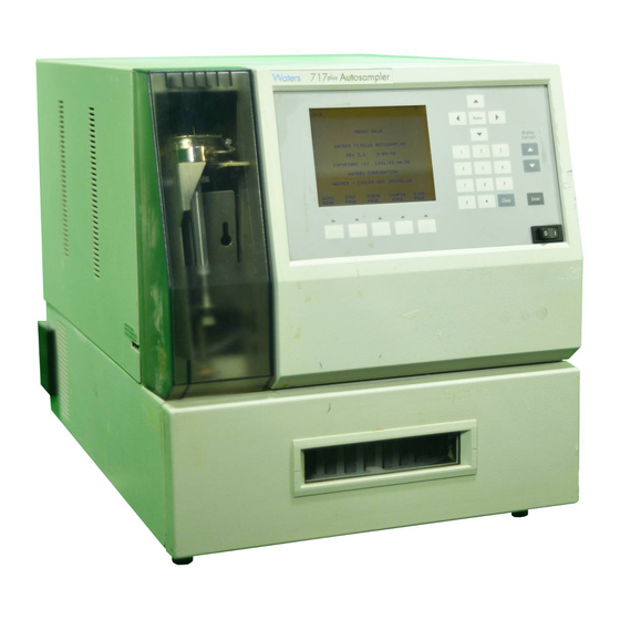
(Figure 1-1) may be used as either a stand-alone unit or as a component in a Waters IEEE-488 based HPLC system. As part of an IEEE-488 based system, the autosampler may be controlled by Waters PowerLine™ System Controllers or Waters Data Workstations. -
Page 20: Features
• Auto Standards - Allows you to run standards automatically during a run. • Auto Transfer - Allows you to program the 717plus to transfer solutions from specified vials to your sample vial; to mix the solution; and to inject. - Page 21 The delay is a programmable interval that occurs after the Inject Stop signal. • Programmable Event - The 717plus includes a programmable event output that can control external devices during a run. IEEE-488 Bus Communication As part of a Waters IEEE-488 system, the Waters 717plus autosampler accepts programming and control signals from an LC system controller.
-
Page 22: Components And Subsystems
Semiprep Chromatography For semiprep chromatography (up to 2 mL injections), the 717plus autosampler may be configured with optional: • 2000 µL sample loop - Required for injections greater than 200 µL • 2500 µL syringe - Speeds pre-injection sequence for samples greater than 150 µL Microbore (<... -
Page 23: Waters 717Plus Autosampler Subsystems
Bottom sensors Sensors Sample Loop Valve (v1) Inlet Line from Pump (Blue) Outlet Line to Column (Red) Figure 1-2 Waters 717plus Autosampler Subsystems Introduction Artisan Technology Group - Quality Instrumentation ... Guaranteed | (888) 88-SOURCE | www.artisantg.com... -
Page 24: Chapter 2 Installation
Installation This chapter describes 717plus installation and setup. It includes procedures for making connections, voltage selection, and configuring optional hardware. 2.1 Site Requirements Required Space Before beginning the installation procedure, note the following autosampler site and utility requirements (Figure 2-1):... -
Page 25: Waters 717Plus Autosampler Site Requirements
Note that cooler performance is derated above 27 °C Humidity 80% maximum relative humidity, non-condensing Do not locate the Waters 717plus in direct sunlight, near heat registers, or under air conditioning vents. Weight Requires a bench capable of supporting at least 75 lbs. -
Page 26: Unpacking And Inspection
5. Grasp the autosampler from the bottom to lift. Do not lift by holding the front panel. 6. Place the 717plus securely on the bench top. Allow clearance for the power cord and ventilation. List of Components The autosampler shipping carton contains: •... -
Page 27: Changing Voltage Configuration
2.3 Changing Voltage Configuration The Waters 717plus autosampler is shipped in a 120 V/60 Hz configuration. If you require a different voltage setting, change the configuration. Tools required: • One small-blade screwdriver • One Phillips-head screwdriver • One pair of needlenose pliers Caution: Disconnect the autosampler power cord before continuing this procedure. -
Page 28: Voltage Selector Card
Attention: Do not use the voltage selector card to compensate for low line voltage. Always use a selection that equals the nominal line voltage, or power STOP surges may damage the instrument. 4. The edge of the voltage card is labeled with four voltages (Figure 2-3). -
Page 29: Removing The Fuse Block
1. Loosen retaining screw. 2. Push clip. 3. Tilt up and slide away from screw. Screw Mount Shoulder Figure 2-4 Removing the Fuse Block 2. Orient the fuse block for the desired voltage (Figure 2-5) as follows: • For single 1/4-inch x 1 1/4-inch fuse arrangements, install the fuse block with the fuse and jumper bar facing away from the cover. -
Page 30: Connecting Fluid And Drain Lines
Observe safe laboratory practices when handling solvents. Refer to the Material Safety Data sheets for the solvents in use. The Waters 717plus Autosampler fluid lines are: • Green - Plastic tubing for needle wash inlet • Yellow - Plastic tubing for needle wash waste •... -
Page 31: Fluid Line Connections
Connecting Fluid Lines To connect the fluid lines (Figure 2-6): Red Line to Column Green Line to Needle Wash Solvent Home Display Contrast Clear Enter Yellow and Clear Lines Blue Line to Pump to Waste Figure 2-6 Fluid Line Connections 1. - Page 32 Ensure that the red and blue fluid lines are in the side panel slots and not STOP pinched between the cover and side panels. Installing Drain Lines Using parts from the 717plus Startup Kit, connect the two drain lines to the drain pans located on the bottom of the autosampler (Figure 2-7) as follows: 1.
-
Page 33: Connecting Communication Cables
LC components. • IEEE-488 - Communicates with a system controller over the IEEE network. • RS-232 - Provides information to RS-232 based data systems such as the Waters 746 Data Integrator. This section describes the communication connections listed above. -
Page 34: Making Terminal Strip Connections
Terminal Strip (removable) RS-232 INJECT STOP PROG EVENT INJECT START INJECT START HOLD HOLD IEEE-488 RS-232 NEEDLE WASH IN (1/16") GREEN IEEE-488 NEEDLE WASH OUT (1/16") YELLOW INPUT VOLTAGE WASTE LINE OUT (1/16") CLEAR RANGE FUSE 85-130 VAC 6.0 A 3.0 A 185-265 VAC Figure 2-8 Autosampler Rear Panel... -
Page 35: Terminal Strip Signals
Output signals the end of the programmed run time 3, 8, 13 Ground Signal ground for cable shields For specific information on signal use with other Waters equipment, refer to the appropriate manual. Electrical Specifications Input (Hold) terminal specifications are: • TTL or switch closure •... - Page 36 Making Cable Connections Tools required: • One small-blade screwdriver • One electrical insulation stripping tool • Signal cable from 717plus Startup Kit Connecting Communication Cables Artisan Technology Group - Quality Instrumentation ... Guaranteed | (888) 88-SOURCE | www.artisantg.com...
-
Page 37: Terminal Strip
System Controller Connections Note: Some system controllers do not allow injections of less than 1 µL. To make injections of less than 1 µL, do not operate the Waters 717plus autosampler over the IEEE bus. Installation Artisan Technology Group - Quality Instrumentation ... Guaranteed | (888) 88-SOURCE | www.artisantg.com... -
Page 38: System Controller Connections
Using a signal (contact closure) from the Waters 717plus autosampler, a Waters system controller can coordinate the start of detectors, pumps, and computers. For specific details on programming a system controller, refer to the system controller operator’s manual. To connect a system controller, connect the Inject Start terminal on the autosampler as... -
Page 39: Auto Zero Connections
Other Waters detectors Auto Zero Detector Data Transfer and Chart marking Using the Inject Start signal from the Waters 717plus autosampler, a Waters detector can: • Start data transfer over the IEEE-488 bus when the autosampler initiates an injection Note: If you specify start by LAC/E, you do not need the Inject Start signal. -
Page 40: Making Ieee-488 Network Connections
Power down all instruments on the IEEE-488 bus before making connections. STOP 1. Connect one end of the IEEE-488 cable to the IEEE connector of the 717plus autosampler. 2. Connect the other end of the IEEE-488 cable to a system controller or to any one of your IEEE-488 components. -
Page 41: Connecting Rs-232 Output To Data Module
2.5.3 Connecting RS-232 Output to Data Module The RS-232 connector on the rear panel allows the autosampler to transfer injection parameters to a data integrator such as the Waters™ 746 Data Integrator. You may use the RS-232 port with any device that can read ASCII code. -
Page 42: Changing The Hardware Configuration
This section covers: • Removing the autosampler cover • Installing the heater/cooler • Installing the auxiliary sample loop 2.6.1 Removing/Replacing the 717plus Cover Caution: To avoid the possibility of electric shock, disconnect the autosampler power cord before continuing this procedure. - Page 43 Attention: Always replace the 717plus autosampler cover to maintain RFI and EMI STOP shielding integrity. Caution: To avoid the possibility of electric shock, do not remove the power supply cover. The power supply does not contain user-serviceable components. Installation Artisan Technology Group - Quality Instrumentation ... Guaranteed | (888) 88-SOURCE | www.artisantg.com...
-
Page 44: Removing The Autosampler Cover
1. Lift up syringe cover to remove. Front Flanges Side Slots (for fluid lines) 2. Remove cover retaining Side Flanges screw. 3. Pull cover back to clear posts, fluid END OF RUN lines, and INJECT START INJECT START front flanges. INJECT START HOLD HOLD... -
Page 45: Installing The Heater/Cooler
• Install the temperature probe To install the heater/cooler: 1. Disconnect the power cord and remove the autosampler cover (see Section 2.6.1, Removing/Replacing the 717plus Cover). 2. Remove the rear chamber assembly by unlatching the side clips, and pulling the assembly back. -
Page 46: Installing Heater/Cooler
Side Clips Heater/Cooler Power Cable Figure 2-12 Installing Heater/Cooler 5. Feed the power cable up through the opening in the chassis and attach it to the J20 connector on the main circuit board (Figure 2-13). Changing the Hardware Configuration Artisan Technology Group - Quality Instrumentation ... Guaranteed | (888) 88-SOURCE | www.artisantg.com... -
Page 47: Connecting The Heater/Cooler Power Cord And Temperature Probe
Heater/Cooler Power Connector (J20) Temperature Probe Opening For Connector Heater/Cooler Power Cable Figure 2-13 Connecting the Heater/Cooler Power Cord and Temperature Probe 6. Push the temperature probe through the grommet located on the floor of the unit behind the carousel drive (Figure 2-14). -
Page 48: Installing The Large Sample Loop
Figure 2-13). 8. Replace the autosampler cover (see Section 2.6.1, Removing/Replacing the 717plus Cover) and reconnect the power cord. 2.6.3 Installing the Large Sample Loop To inject sample volumes greater than 200 µL, you must install the auxiliary loop. Caution: To avoid the possibility of electric shock, disconnect the autosampler power cord before continuing this procedure. -
Page 49: Disconnecting The Sample Loop
• Auxiliary loop from 717plus Startup Kit • Union from 717plus Startup Kit To install the loop: 1. From the 717plus front panel, set system flow to 0 mL/min. 2. Turn off the autosampler, disconnect the power cord, and remove the autosampler cover (see Section 2.6.1, Removing/Replacing the 717plus... - Page 50 7. Complete the configuration procedures discussed in Section 3.6.3, Entering Hardware Changes. If the auxiliary loop was added to a previously configured autosampler, perform the procedures in: • Section 3.3, Flushing the Autosampler • Section 3.7, System Verification • Section 4.5.2, Performing a Purge Changing the Hardware Configuration Artisan Technology Group - Quality Instrumentation ...
-
Page 51: Startup And Configuration
Waters 717plus autosampler. 3.1 Powering Up the Autosampler Note: If the 717plus autosampler is part of an IEEE-488 system, power up the 717plus autosampler before powering up the system controller. Powerup To power up the 717plus autosampler: 1. -
Page 52: Using The Front Panel
3-3) until the screen text is in focus. 3.2 Using the Front Panel Use the front panel (Figure 3-3) to configure the 717plus system and perform injection programming. This section describes: • Accessing menus using menu function keys • Entering operating parameters using the keypad Startup and Configuration Artisan Technology Group - Quality Instrumentation ... -
Page 53: Accessing Menus
Carousel Arrow Keys Release/Engage (Cursor control) INIT Homing syringe Home Menu: Main Wa t e r s 7 1 7 p l u s A u t o s a m p l e r R e v 2 . 0 2 / 1 / 9 3 C o p y r i g h t ( C ) 1 9 9 1 , 9 3 CAROUSEL... -
Page 54: 717Plus Autosampler Menu Flowchart
Menu: User Maintenance Diagnostic: Injector Calibration Menu: Calibration Pages Diagnostic: Auto Zero Pressure Diagnostic: Valve & Motor Operations Figure 3-4 717plus Autosampler Menu Flowchart Startup and Configuration Artisan Technology Group - Quality Instrumentation ... Guaranteed | (888) 88-SOURCE | www.artisantg.com... -
Page 55: Entering Operating Parameters
field. 3.3 Flushing the Autosampler Solvent Considerations When flushing or purging your 717plus, make sure the solvent is properly degassed and miscible with the previous mobile phase in the autosampler. Flushing To flush the 717plus autosampler: 1. -
Page 56: Purging The Autosampler
3.4.1 Purging the Autosampler Before calibrating the seal pak, run a purge to ensure that there is no air in the autosampler, the mobile phase is fresh, and there are no bubbles in the syringe. 1. Using a degassed solution of 100 percent methanol, set the solvent delivery pump to 1 mL/min. -
Page 57: Calibrating The Seal Pak
Main Page Diag Page Menu: Diagnostic UserMaint Page Menu: User Maintenance Page Menu: Calibration AutoZero Page DIAG Diagnostic: Auto Zero Pressure Ambient pressure with no correction must be between -90 psi and 750 psi. Otherwise, manually adjust transducer. Pressure Correction Pressure (psi) Autozero Pressure... - Page 58 To attain sufficient backpressure without a column, it may be necessary to partially cap the red line with the union and fitting plug assembly included in the 717plus Startup Kit. 2. To access and run the seal pak calibration, press the keys indicated in the flowchart below...
-
Page 59: Path To Seal Pak Calibration Page
Menu: Main Diag Page Menu: Diagnostic UserMaint Page Menu: User Maintenance Page Menu: Calibration Page DIAG Diagnostic: Injector Calibration Set system pressure to 400 to 600 psi. Down Seal Counts Up Seal Counts Seal Width Counts Pressure Start Page Start Figure 3-6 Path to Seal Pak Calibration Page Calibrating the Seal Pak Artisan Technology Group - Quality Instrumentation ... -
Page 60: Priming The Needle Wash Pump
3.5 Priming the Needle Wash Pump To prime the needle wash pump: 1. Ensure that the needle wash supply line (green) is in the solvent bottle and the waste line (yellow) is in an appropriate container. 2. To prime the needle wash, press the keys outlined in the flowchart below (Figure 3-7). -
Page 61: Configuring The Autosampler
3.6 Configuring the Autosampler Configuring the Waters 717plus Autosampler requires: • Setting parameters to enable the autosampler to communicate with other modules in the LC system • Recording changes to autosampler hardware (syringe size and sample loop volume) 3.6.1 Overview of Configuration Refer to the Autosampler Configuration flowchart... -
Page 62: Autosampler Configuration Flowchart
Configure autosampler Attach cable Connect to IEEE-488 (Section 2.5.2) system controller? and set IEEE-488 address (Section 3.3.1). 3.6.2). Attach RS-232 cable Connect to (Section 2.5). data integrator Enter delay required to set or workstation? up data files (Section 3.3.1). 3.6.2). Connect cables to HOLD Allow other terminals (Section 2.5.1). -
Page 63: Configuration Parameters
Table 3-2 Configuration Parameters Configuration Parameter Description Page Purge In Idle? Enables purging every 60 minutes while the 717plus is idle. See Section 4.8.5, Using Buffered Mobile Phase. Vials Between Purges 1 Enables automatic purging during an auto run. See Section 4.8.4, Purging During an... -
Page 64: Setting Parameters For Lc System Operation
The Report Delay provides time for the data integrator to process data from a run before a new injection begins. If a data integrator is attached to the LC system, set the delay as follows: 1. From the 717plus Main Menu, press Config Page. -
Page 65: Setting The Integrator Report Delay
2. On Configuration Page 1 (Figure 3-9), highlight the Report Delay field and enter delay time in minutes. IDLE Edit: Configuration Page 1 of 4 Use Door Sensor? Purge In Idle? Vials Between Purges: Halt Bad Comp Check? Report Delay (min): LCD Contrast Adjust? Main PrevCfg... -
Page 66: Hold Logic
I D L E E d i t C o n f i g u r a t i o n P a g e 2 o f 4 H o l d C o n t a t S e n s e ? H o l d I n p u t O f f I n j e c t S t a r t P u l s e ( s e c ) :... - Page 67 2 to 29. The default IEEE-488 address is set to 30. Note: To use the Waters 717plus Autosampler in an IEEE-488 network, you must change the address. To change the address: 1.
-
Page 68: Entering Hardware Changes
IDLE Edit: Configuration Page 4 of 4 IEEE Address Assignment Installed IEEE Address: Desired IEEE Address: Press REBOOT SYSTEM softkey to install desired IEEE address. REBOOT PrevCfg Main NextCfg SYSTEM Page Page Page Figure 3-11 Setting IEEE-488 Address 3.6.3 Entering Hardware Changes To enable the autosampler to adjust to changes in hardware configuration (syringe and sample loop size), you must enter the changes on Configuration Page 3 (Figure... -
Page 69: Configuration Page 3
Page Page Page Figure 3-12 Configuration Page 3 Entering Syringe Size To record a change in the syringe size: 1. From the 717plus Main Menu, press Config Page. 2. Press Next Page twice to access Configuration Page 3. 3. Select the appropriate Syringe Volume, and press Enter. -
Page 70: System Verification
1. Using a degassed solution of 100 percent methanol, set the solvent delivery pump to 1 mL/min. Note: For daily verification, use the mobile phase that you normally run. 2. From the 717plus Main Menu, press Edit Purge (Figure 3-13). -
Page 71: Power Down And Storage
5. Purge the autosampler. 3.8.2 Powering Down This section covers procedures for powering down the Waters 717plus autosampler for 1 to 14 days. 1. If the current mobile phase is water, replace the water with a solution of 90 percent methanol and 10 percent water. -
Page 72: Storage
3.8.3 Storage This section covers procedures for long-term storage of the Waters 717plus autosampler. If the autosampler will be stored for more than two weeks: 1. Remove buffered mobile phases (see Section 3.8.1, Removing Buffered Mobile Phase). 2. Power down the autosampler (see Section 3.8.2, Powering... -
Page 73: Operating The Autosampler
Figure 4-1 provides an overview of autosampling. Note: If the Waters 717plus autosampler is part of an IEEE-488 network, power up the autosampler before powering up the system controller. Overview of Operation Artisan Technology Group - Quality Instrumentation ... Guaranteed | (888) 88-SOURCE | www.artisantg.com... - Page 74 Operating the autosampler Power up autosampler, detectors, and other LC components before system controller. Prepare samples and load carousel. Select needle wash based on sample and mobile chemistry. Flush system. Changing Perform purge and mobile compression check. phase? Purge autosampler. Program auto run.
-
Page 75: Preparing Samples
4.2 Preparing Samples To prepare and load samples into the autosampler, you must: • Prepare the sample • Select and fill a sample vial 4.2.1 Preparing Samples Minimum sample preparation consists of dissolving the sample: • In a solvent that is compatible with the mobile phase and column chemistry •... -
Page 76: Preparing Samples
Preparing samples (Section 4.2.1). Normal phase Dissolve in column? mobile phase. Same or weaker Reverse phase organic component column? as mobile phase. Use a low salt Ion exchange? concentration. Dissolve in mobile GPC? phase (from the same bottle). Filter samples with 0.5 µ... -
Page 77: Selecting Sample Vials
filters or the column inlet fitting which would result in an increase in backpressure. 4.2.2 Selecting Sample Vials The Waters 717plus autosampler is compatible with the complete line of Waters chromatography sample vials. Attention: Use only sample vials and supplies from Waters. Use of non-Waters sample STOP vials, low-volume inserts, or septa may result in damage to the needle. -
Page 78: Selecting A Needle Wash Solvent
Attention: Do not overtighten the cap with a self-sealing septum. Overtightening (septum STOP dimples in) may cause the cap to fit incorrectly. Also, the use of self-sealing septa may cause variable injector volumes on multiple injections due to vacuum buildup. Screw Cap Limited Volume Insert... - Page 79 Table 4-1 Suggested Needle Wash Solvents (Continued) Mobile Phase Needle Wash Normal phase Mobile phase Mobile phase Ion exchange Paired ion reagent in H To use a needle wash: 1. Select a needle wash solvent based on the chemistry of the mobile phase. 2.
-
Page 80: Loading The Carousel
Needle wash pump location Clear Enter Figure 4-4 Improper Needle Wash Solvent Location 3. With the 717plus autosampler powered on, prime the needle wash pump (see Section 3.5, Priming the Needle Wash Pump). 4.4 Loading the Carousel Attention: Use only Waters™ grey carousels. The Waters 717plus autosampler does not STOP work with WISP white or brown carousels. -
Page 81: Inserting The Carousel
3. Place the assembled sample vials in the carousel and note the location. The vial number is located on the rim of the carousel. Attention: Use of non-Waters™ sample vials, low-volume inserts, and septa may STOP result in damage to the needle. -
Page 82: Ensuring Reproducibility
Test) to verify the integrity of the sample loop. 4.5.2 Performing a Purge Perform a purge from the Purge and Compressibility Page. Purging the Autosampler To perform a purge using the default values, press the Waters 717plus autosampler keys as indicated below (Figure 4-6): Operating the Autosampler Artisan Technology Group - Quality Instrumentation ... - Page 83 • The auxiliary loop is installed The purge time setting depends on: • Flow rate of the mobile phase • Sample loop size To change the Purge Time: 1. From the 717plus Main Page, press Purge Page to display the Purge and Compressibility page (Figure 4-7).
-
Page 84: Autosampler Volume
PURGE Edit: Purge and Compressibility Purge Time (min): Compression Check? Compression Pressure (psi): Pressure Decay Time (min): Compressible Volume ( l): Pressure Change (psi) Compressed Volume (psi) Start Main Purge Page Figure 4-7 Purge and Compressibility Page 2. Calculate the purge time based on the flow rate and sample loop size. The time must be sufficient to allow three volume changes of the autosampler. -
Page 85: Performing A Compression Check
Table 4-3 lists sample purge times for the two sample loops at selected flow rates. Table 4-3 Purge Time Examples Sample Flow Rate Purge Time Loop (mL/min) (min) Normal 12.5 >1 Auxiliary 19.4 4.5.3 Performing a Compression Check The compression check tests for gas in the mobile phase, and, when enabled, occurs immediately after a purge. - Page 86 Compression Pressure For testing the compressibility of the mobile phase, use 30 psi. For leak testing, use the maximum pressure. Range 30 to 350 psi Default Pressure Decay Time Sets the length of time the system pauses before recompressing the mobile phase in the sample loop.
-
Page 87: Running A Compressibility Test
Performing a Compression Check To perform a compression check, press the keys indicated in Figure 4-8: Main Page Purge Page PURGE Edit Purge and Compressibility Page Purge Time (min): Compression Check? Compression Pressure (psi): Pressure Decay Time (min): Compressible Volume ( l): Pressure Change (psi) Compressed Volume (psi) Start... -
Page 88: Running Autosampling
• Unattended operation - Provides injection start and stop output signals for controlling external devices. • Programmable output signal - Allows the 717plus to control external devices during a run. • Auto Standard, Auto Addition, and Auto Transfer functions - Allow automated operation for standards, pre-injection addition of samples, and automatic pre-injection transfer and mixing. -
Page 89: Programming Auto Run
Load samples Program the step on the Auto Run page (Section 4.6.1) Program step functions for the step (Section 4.6.2) Program the option for the step: Auto Standards (Section 4.6.3) Auto Addition (Section 4.6.4) Auto Transfer (Section 4.6.5) Program the event output for the step (Section 4.6.6) Figure 4-9 Overview of Programming... -
Page 90: Edit: Auto Run Screen
4.6.1.1 Using the Auto Run Screen Display the Edit: Auto Run screen by pressing the Auto Page key on the Main Menu. The Edit: Auto Run screen (see Figure 4-10) lets you program up to 96 steps. I D L E E d i t : A u t o R u n F r o m I n j... - Page 91 1. Use the arrow keys to move to a step number where the new line will be inserted. 2. Press Insert Line. The 717plus duplicates the previous line, and renumbers all subsequent lines. Deleting a Line To delete a line: 1.
- Page 92 Step 1. Place the cursor on a blank line, then press Enter. The 717plus inserts a new line and copies the information, including step function and option settings, from the previous line. You can program up to 96 different steps. Each vial included in the step shares the same number of injections, injection volume, run time, step functions, and options.
-
Page 93: Programming Step Functions
Inj Vol 4. Enter the injection volume. The maximum injection volume depends on the size of the sample loop. Sample Loop Size Range (µL) Standard 0 to 200 Auxiliary 0 to 2000 Run Time 5. Enter the run time in minutes. Valid entries are 0 to 999.9. The run time clock starts when the sample enters the mobile phase stream. -
Page 94: Edit: Step Function Screen
I D L E E d i t : S t e p F u n c t i o n 1 o f 1 T r n s E d i t i n g S t e p : N e e d l e P o s i t i o n ( % ) ? 1 0 0 P u r g e A f t e r S t e p ? -
Page 95: Using Auto Standards
The picture of the vial displayed in the upper-right corner of the screen shows the selected needle position. Purge After Step 4. If desired, move the cursor to Purge After Step?, and select Yes. Default is No. Step function purges use the Purge Parameters set on the Purge and Compressibility screen. - Page 96 • Do not have to be in consecutive positions in the carousel • Can be different for each step Auto Standards Sequence During an Auto Standards run, the 717plus: • Injects standards (specified on Auto Standards screen) • Injects samples (specified on Auto Run screen) •...
-
Page 97: Edit: Auto Standards Screen
Programming Auto Standards To program Auto Standards: 1. From the Edit: Auto Run screen (see Figure 4-10), select a step, then press Step Function to display the Edit: Step Function screen. Note: For instructions on setting Needle Position and Purge, refer to Section 4.6.2, Programming Step Functions. - Page 98 1 to 99 Run Time Total run time from injection to Inject Stop signal, 0.0 to 999.9 min Dependent on sample loop installed in Waters 717plus Running Auto Standards To start the Auto Run: 1. When programming is complete, press...
-
Page 99: Example Auto Standard Run 1
4.6.3.3 Example Auto Standard Run In an Auto Standards run, standards always run at the beginning of a step, and may run during or at the end of a step. Whether standards run during or at the end of a step is determined by the number of vials in a step and the number of vials specified to run between standards. -
Page 100: Using Auto Addition
Auto Run Auto Standards Step From Vials Between =4 Standard Vial = 1 Vial Vial Vial Vial Vial Vial Vial Vial Vial Vial Figure 4-14 Example Auto Standard Run 2 4.6.4 Using Auto Addition This section describes: • Overview of Auto Addition •... - Page 101 Auto Addition Sequence During an Auto Addition run, the 717plus: • Withdraws from all common vials (specified on Auto Addition screen) • Withdraws from the sample vial (specified on Auto Run screen) • Delays, if specified • Injects Section 4.6.4.3, Example Auto Addition Run, includes an example of an Auto Addition run.
-
Page 102: Auto Addition Screen
Common Vol Volume to withdraw from common vial: 0.0 to 200.0 µL or 0.0 to 2000.0 µL Dependent on sample loop installed in Waters 717plus Operating the Autosampler Artisan Technology Group - Quality Instrumentation ... Guaranteed | (888) 88-SOURCE | www.artisantg.com... - Page 103 field to None), you delete the information programmed for Auto Addition. 4.6.4.3 Example Auto Addition Run In an Auto Addition run, the 717plus withdraws the specified volume from up to 5 common vials, withdraws the specified volume from the sample vial, then injects the total volume of...
-
Page 104: Using Auto Transfer
Auto Run Auto Addition Common Vials Step From Withdraw From From Vial 10 Vial 1 From Vial From Inject total of Vial 2 Vial 20 all withdrawn Vial Vial Vial Vial volumes Total volume sent to column Withdraw From From Vial 1 Vial 10 Vial... - Page 105 The Auto Transfer table is saved in permanent memory. Auto Transfer Sequence During an Auto Transfer run, the 717plus: • Aspirates an air gap into the needle to prevent diffusion of sample • Withdraws a transfer solution (specified on the Auto Transfer screen) •...
-
Page 106: Auto Transfer Screen
2. From the Edit: Step Function screen (see Figure 4-11), press the down-arrow key to move the cursor to the Option? field. 3. Press the right-arrow key to move the cursor to the Trns field (see Figure 4-11). The Trns Page key appears on the screen. 4. - Page 107 The Dispense Needle setting affects dispensing only. When the 717plus withdraws from the transfer vial or from the sample vial during mixing, the needle position is at 100%.
- Page 108 4.6.5.3 Example Auto Transfer Run Transfer Before Step If you select Step as the Transfer sequence, the 717plus transfers a solution to the sample vial one time at the beginning of a step. The solution is transferred from the specified transfer vial into the first sample vial in the step.
-
Page 109: Transfer Before Step
Figure 4-18 Transfer Before Step Transfer Before Vial If you select Vial as the Transfer sequence, the 717plus transfers a solution to the sample vial one time for each vial in the step. The solution is transferred before the first injection of each vial. -
Page 110: Transfer Before Vial
Figure 4-19 Transfer Before Vial Transfer Before Injection If you select Injection as the Transfer sequence, the 717plus transfers a solution to the sample vial before every injection from every vial. Use this method for multiple (progressive) dilutions of samples. -
Page 111: Programming The Event Output
4.6.6 Programming the Event Output The 717plus includes a contact closure that you can program to turn on or off up to four times during each step of an Auto Run. Use the Edit: Step Function screen to program the contact states and event times. -
Page 112: Starting And Stopping An Auto Run
I D L E E d i t : S t e p F u n c t i o n 1 o f 1 T r n s E d i t i n g S t e p : N e e d l e P o s i t i o n ( % ) ? 1 0 0 P u r g e A f t e r S t e p ? -
Page 113: Monitoring Auto Run Status
Stopping To stop an Auto Run: 1. Press Stop Run. A prompt appears: Do you really want to stop the auto run? 2. Press to stop the run. If the autosampler is in the pre-injection sequence (sample is still in the sample loop), you may either: •... -
Page 114: Making A Stat Run
The Auto Run Status screen (see Figure 4-22) displays: • Step and Vial Number - Appears in upper right corner, along with a blinking cursor that indicates that the run is in progress. • Vial # - Displays current sample vial number. •... -
Page 115: Edit Stat Run Screen
IDLE 22¡ Edit: Stat Run From Time Step Vial Vial 10.0 End of Table Main Start Stat Page Figure 4-23 Edit Stat Run Screen Entering Stat Run Parameters Note: You must enter a value for each parameter. For parameter ranges, see Section 4.6.1, Programming Auto Run. -
Page 116: Status: Stat Run
Monitoring a Stat Run When the Stat Run begins, the Stat Run Status screen (Figure 4-24) appears. STAT 28¡ Step 1 Vial 1 Status: Stat Run Vial # of 2 Volume ( l) 10.0 Runtime (min) 12.0 Time Remaining (min) Auto Stat Stop... -
Page 117: Sampling Considerations
To stop a Stat run: 1. Press Stop Run. A prompt appears: Do you really want to stop the Auto Run? 2. Press to stop the run and return to the Main Menu. 4.8 Sampling Considerations The sample and chromatography method you use may require changing the configuration of the autosampler. -
Page 118: Microbore/Semiprep Injections
90 minutes to reach 4° C from an ambient temperature of 27° C. 4.8.2 Microbore/Semiprep Injections The Waters 717plus a utosampler may be physically reconfigured to facilitate microbore injections (< 5 µL) and semiprep injections (> 150 µL). -
Page 119: Changing Syringe Configuration
Making Microbore Injections To make microbore injections: 1. Replace the standard 250 µL syringe with a 25 µL syringe (see Section 5.2, Replacing the Syringe). 2. Enter the hardware change on Configuration Page 3 by pressing the keys indicated in Figure 4-26. -
Page 120: Entering The Semiprep Configuration
Making Semiprep Injections Semiprep chromatography involves large samples and high flow rates. To make semiprep injections: 1. To increase sample injection volume, replace the standard 250 µL syringe with a 2500 µL syringe (see Section 5.2, Replacing the Syringe). 2. Connect the auxiliary loop to the standard sample loop (see Section 2.6.3, Installing the Large Sample Loop). -
Page 121: Sample Draw Rate
4. If required by sample viscosity, change the draw rate (see Figure 4-28). 5. Load sample into an appropriate size vial (see Section 4.2.2, Selecting Sample Vials). 4.8.3 Injecting Viscous Samples Slowing the sample withdrawal rate improves injection accuracy with viscous samples. The allowable range in draw rate for various syringes is shown in Table 4-4. -
Page 122: Purging During An Auto Run
Menu: Main Config Page Configuration Page 1 NextCfg Page Configuration Page 2 NextCfg Page IDLE Edit: Configuration Page 3 of 4 1.00 Draw Rate ( l/sec): 2500 Syringe Volume ( l)? Loop Volume ( l)? 2000 1.00 PrevCfg Main NextCfg Page Page Page... -
Page 123: Using Buffered Mobile Phase
When the compression check is enabled (see Section 4.5.3, Performing a Compression Check), you may enable the autosampler to stop the next injection if the compression check fails. Enabling Auto Purging To enable auto purge between sets of vials, enter the number of vials between purges (Figure 4-29). -
Page 124: Enabling Purge In Idle
• Remove the mobile phase before powering down (see Section 3.8, Power Down and Storage). Note: Program the pump for a minimal flow after the last run to prevent damage to LC components. Purge in Idle During unattended (overnight) runs using buffered mobile phases, enable the purge in idle mode to prevent buffer buildup in the autosampler. -
Page 125: Chapter 5 Maintenance
Maintenance This chapter covers 717plus maintenance. Procedures are provided for defrosting the heater/cooler and for replacing the syringe, seal pak, and in-line filters. 5.1 Defrosting the Heater/Cooler When to Defrost If the Heater/Cooler fails to reach the lowest setpoint at recommended ambient conditions (16 to 27°... -
Page 126: Defrost Menu Flowchart
Main Page Diag Page Menu: Diagnostic UserMaint Page Menu: User Maintenance Defrost Page DIAG Diagnostic: Defrost The defrost cycle takes 60 minutes The door must be left open. After the defrost cycle the heater/cooler is turned off. UserMaint Start Defrost Page Start Defrost... -
Page 127: Replacing The Syringe
• Plunger tip becomes worn • You want to use the optional 25 or 2500 µL syringes Attention: Use only Waters-approved syringes in the autosampler (see Appendix B for STOP ordering information). Unapproved syringes may cause erroneous results and/or may not meet required safety standards. -
Page 128: Syringe Assembly Components
Figure 5-2 Syringe Assembly Components Lowering the Bracket To lower the mounting bracket: 1. Lower the bracket by pressing the keys indicated in Figure 5-3. Maintenance Artisan Technology Group - Quality Instrumentation ... Guaranteed | (888) 88-SOURCE | www.artisantg.com... -
Page 129: Positioning The Syringe For Removal
Fill Wash Pump? Figure 5-3 Positioning the Syringe for Removal 2. At the 717plus keypad, use arrow keys to move to the Valve 3 field. Highlight the Open entry, and press Enter. 3. Use the arrow keys to move to the syringe field. Highlight the... -
Page 130: Installing The New Syringe
3. Tighten the syringe hand-tight. 4. At the 717plus keypad, use the arrow keys to move to the Syringe field. Highlight Empty entry, and press Enter. The mounting block moves upward to allow you to install the knurled nut. - Page 131 6. To reset the Valve and Motor Operations screen to the original state, move the screen arrow to the field: To execute Normal State press Enter. and press Enter. 7. To return to the Main Menu, press UserMaint Page, Diag Page, and Main Page.
-
Page 132: Changing Syringe Volume
Menu: Main Config Page Configuration Page 1 NextCfg Page Configuration Page 2 NextCfg Page IDLE Edit: Configuration Page 3 of 4 Draw Rate ( l/sec): 1.00 Syringe Volume ( l)? 2500 Loop Volume ( l)? 2000 PrevCfg NextCfg Main Page Page Page Figure 5-5 Changing Syringe Volume... -
Page 133: Replacing The Seal Pak
Purging the Syringe Purge the autosampler a minimum of three times to ensure that there are no bubbles in the syringe. To purge: 1. Set the pump flow to 1 mL/min. 2. From the Main Menu, press Purge Page. 3. Press Start Purge. -
Page 134: Removing The Injector
1. Turn off the unit and disconnect the power cord from the rear panel. 2. Remove the autosampler cover (see Section 2.6.1, Removing/Replacing the 717plus Cover). 3. Using a Torx T20 wrench, remove the two screws securing the injector safety shield (located at the top of the shield). -
Page 135: Removing The Seal Pak
6. Disconnect the two needle wash lines from the right side of the injector (Figure 5-6). Power Motor Cable Sensor Cable Mounting Screw Needle Wash Lines Mounting Screws Figure 5-6 Removing the Injector (shown with Safety Shield Removed) 7. Using the long flat-blade screwdriver, loosen the three mounting screws securing the injector to the floor of the compartment (see Figure 5-6). -
Page 136: Replacing The Needle
Disconnect tubing here Seal Pack Mounting Screws Figure 5-7 Bottom View of Injector 4. Pull the seal pak out of the injector. 5.3.3 Replacing the Needle To replace the needle: 1. Unscrew the compression screw on the needle (Figure 5-8). Maintenance Artisan Technology Group - Quality Instrumentation ... -
Page 137: Installing A New Seal Pak
Needle Compression Screw Needle port must face left side Left Side Figure 5-8 Needle Removal 2. Pull the needle down. 3. Rotate the motor drive shaft until the needle mounting block is as high as it can 4. Orient the needle port toward the left side of the injector (Figure 5-8). -
Page 138: Installing The Injector
3. Connect the outlet line from the union fitting to the port on the left side. Tighten the connections 1/4-turn after making a finger tight connection. 4. Connect the inlet line (with in-line filter) to the port on the right side. Tighten the connections 1/4-turn after making a finger tight connection. -
Page 139: Replacing In-Line Filters
1. Set pump flow rate to 0 mL/min. 2. Remove the autosampler cover and locate the in-line filters (Figure 5-9). Note: For procedures on removing the 717plus cover, refer to Section 2.6.1, Removing/Replacing the 717plus Cover. Replacing In-Line Filters Artisan Technology Group - Quality Instrumentation ... Guaranteed | (888) 88-SOURCE | www.artisantg.com... -
Page 140: Locating In-Line Filters
In-Line Filter (inlet side) In-Line Filter (inlet side) Figure 5-9 Locating In-Line Filters 3. Holding the in-line filter with a 5/8-inch wrench, disconnect both compression screws with the 5/16-inch wrench. 4. Repeat step 2 on the other in-line filter. 5. Disassemble each filter using two 5/8-inch wrenches. 6. - Page 141 10. Flush the autosampler at 1 mL/min for 10 minutes. 11. Inspect the in-line filters for leaks, and tighten 1/4-turn as required. 12. Replace the autosampler cover (see Section 2.6.1, Removing/Replacing the 717plus Cover). Maintenance Artisan Technology Group - Quality Instrumentation ... Guaranteed | (888) 88-SOURCE | www.artisantg.com...
-
Page 142: Chapter 6 Troubleshooting
When You Call If you cannot correct a condition using the procedures in this chapter, contact Waters. You can contact Waters Technical Service at (800) 252-4752, U.S. and Canadian customers only . Other customers, call your local Waters subsidiary or your local Waters Technical Service Representative, or call Waters corporate headquarters for assistance at (508) 478-2000 (U.S.). -
Page 143: Error Message Type
9. Type and serial number of column 10. Sample matrix and components 11. Data system 12. Software version (if applicable) 6.2 Error Messages This section describes the Waters 717plus Autosampler error messages. The six error message types provide information about autosampler components and subsystems (Table 6-1). -
Page 144: Informational Error Messages
Table 6-3 CAL Error Messages Error Message Solution CAL: Could not find bottom sensor Recalibrate, call Waters CAL: Could not find upper seal Recalibrate, call Waters Error Messages Artisan Technology Group - Quality Instrumentation ... Guaranteed | (888) 88-SOURCE | www.artisantg.com... -
Page 145: Carousel (Car) Error Messages
1. Press Clear. 2. Open sample compartment door and remove carousel. 3. Clean carousel. 4. Insert the clean carousel or use a different Waters carousel (grey only). 5. If carousel errors continue, call Waters. Troubleshooting Artisan Technology Group - Quality Instrumentation ... Guaranteed | (888) 88-SOURCE | www.artisantg.com... -
Page 146: Car Error Messages
Table 6-4 CAR Error Messages Error Message Solution CAR: Both carousel lift sensors on Reset autosampler, call Waters CAR: Cannot run with door open Close door CAR: Carousel homing deviation Follow the procedure above for clearing carousel errors CAR: Could not engage carousel... -
Page 147: H/C Error Messages
Solution H/C: Door open time exceeded limit Close door and allow sample compartment to equilibrate H/C: High temp limit exceeded Reset autosampler, call Waters H/C: Internal fan failure Call Waters H/C: Low temp limit exceeded Reset autosampler, call Waters H/C: Temp (temperature) control has a... -
Page 148: Syringe (Syr) Error Messages
Perform leak test (Section 6.4.2, Valve (compression) check Leak Test) INJ: Top sensor active Reset autosampler, call Waters 6.2.6 Syringe (SYR) Error Messages Error Message Solution SYR: Both syringe sensors on Reset autosampler, call Waters SYR: Cannot move with v2 and v3 closed... -
Page 149: Autosampler Troubleshooting
Table 6-7 Autosampler Troubleshooting Symptom Possible Cause Corrective Action Autosampler does Autosampler not Ensure power cable is properly not run (fan and connected to power connected to power source and front panel lights source autosampler. off) No power at outlet Check the outlet by connecting another electrical unit known to be working and verify if the unit operates. - Page 150 Corrective Action Sample compartment Close sample compartment door. If door opened problem continues, contact Waters. Sample carriage error Contact Waters. Defective circuit board Contact Waters. Leak from fluid Loose or Verify fittings and ferrules for system (needle, overtightened under/overtightening and wear.
- Page 151 Table 6-7 Autosampler Troubleshooting (Continued) Symptom Possible Cause Corrective Action Autosampler is Lower the needle wash solvent siphoning solvent reservoir. from needle wash reservoir Sample injection Defective injection Purge the autosampler. If problem problem (such as valve continues, repair/replace the valve. sample not being injected, abnormal peak shape)
- Page 152 Autosampler stuck in Restart operation to reposition valve. If purge (valve 1 closed) problem continues, repair/replace valve (call Waters). Blocked injection Purge the autosampler. If problem valve continues, repair/replace the injection valve. Leak within Check for leaks.
- Page 153 Enter correct sample vial number in autosampler. Sample vial Verify information on sample vial. mislabeled Change label if necessary. Misaligned sample Call Waters. transport system Incorrect sample Incorrect injection Compare injection volume value and volume injected volume specified vial position. Enter correct injection volume value in autosampler.
- Page 154 Make injections without a cap in place, vial remove excess sample from the vial, or loosen cap on the self-sealing septum. Vials repeatedly Incorrect vials being Use Waters vials. break used Incorrect caps being Use Waters caps. used Caps not put on Ensure that caps are on properly.
- Page 155 Remove sample vial cap and replace removed from sample with a septum and cap. vial Replace the autosampler needle. Incorrect vials being Use Waters recommended vials. used Replace the autosampler needle. Septum too resistant Ensure that only one septum is being used at a time.
-
Page 156: Troubleshooting Procedures
The valve test diagnostics test is used to diagnose a faulty valve. This test STOP must only be used with the help of a qualified Waters Service representative. 6.4.1 Manual Syringe Purge In the event that repeated purges do not remove air from the syringe, perform a manual purge. -
Page 157: Valve Leak Test
DIAG Diagnostic: Valve and Motor Operations Valve1? Open Closed Valve2? Open Closed Valve3? Open Closed Valve4? Open Closed Needle? Stream Seal Vial Fill Empty Home Syringe? Wash Pump? To execute Normal State press ENTER Pressure UserMaint Page Figure 6-1 Positioning the Syringe for Manual Purge 3. -
Page 158: Valve And Motor Operations
Preparing for the Valve Test This procedure requires a pump that can deliver at least 5000 psi without leaking and has a pressure gauge. 1. Open the sample compartment door, remove the carousel, and place a beaker under the injector needle. 2. - Page 159 To run a valve test: 1. For each test, set valves and needle on the Valve and Motor Operations page as follows: Test Checks Step 1 Step 2 Step 3 Step 4 Step 5 V1 and injector Needle in V3 Open —...
-
Page 160: Manual Transducer Adjustment
5. Repeat steps 1 through 4 for each test. 6. If the injector fails to calibrate, or the valves fail to maintain the required pressure, contact Waters Technical Service (refer to the sales/subsidiary list at the back of this document). -
Page 161: Accessing The Auto Zero Pressure
4. Power up the autosampler. 5. Access the Auto Zero Pressure page by pressing the keys indicated in Figure 6-3. Main Page Diag Page Menu: Diagnostic UserMaint Page Menu: User Maintenance Page Menu: Calibration AutoZero Page DIAG Diagnostic: Auto Zero Pressure Ambient pressure with no correction must be between -90 psi and 750 psi. -
Page 162: Adjusting The Transducer
+750 psi. 8. Perform an auto zero (Section 3.4.2, Auto Zeroing the Transducer). 9. Replace the autosampler cover (see Section 2.6.1, Removing/Replacing the 717plus Cover). Troubleshooting Procedures Artisan Technology Group - Quality Instrumentation ... Guaranteed | (888) 88-SOURCE | www.artisantg.com... -
Page 163: Operational Specifications
Appendix A Specifications This appendix includes information on: • Operational specifications • Mechanical specifications • Environmental specifications • Power requirements • Communications Table A-1 Operational Specifications Condition Specification Injection Volume Range 0.1 µL to 2000 µL in 0.1 µL Increments Linearity (1 to 100 µL) >... -
Page 164: Mechanical Specifications
Table A-2 Mechanical Specifications Condition Specification Wetted Surface Materials 316 Stainless Steel, Teflon, Glass, Fluoraloy-08 R, UHMWPE Number of Sample Vials 1 to 96 Number of Injections Programmable 1 to 99 injections per vial Allowable Solvents All standard LC solvents Inlet Tubing to Injector 0.040 I.D. -
Page 165: Power Requirements
Table A-4 Power Requirements Voltage Range (VAC)* Frequency (Hz) Current 85 to 130 50 or 60 Hz 5 A maximum 185 to 265 50 or 60 Hz 4 A maximum *The range is selected via the power entry module on the rear panel (see Section 2.3.2, Changing Voltage Configuration). -
Page 166: Spare Parts
Appendix B Spare Parts The following spare parts are approved for customer installation. Any parts not listed in this section may require installation by a trained service representative. Table B-1 Spare Parts Description Part Number Battery WAT080443 Cap for 1 mL vial (1000/pkg) WAT078515 Cap, black phenolic for 4 mL screw top vial (144/pkg) WAT072711... - Page 167 Table B-1 Spare Parts (Continued) Description Part Number Low-volume insert, 150 µL glass (100/pkg) WAT072294 Low-volume insert, spring for 250 µL (144/pkg) WAT072708 Low-volume insert, spring for 150 µL (100/pkg) WAT072289 Power cord, 110 V WAT097194 Power cord, 220 V WAT097410 Pump, needle wash, assembly WAT078979...
- Page 168 Table B-1 Spare Parts (Continued) Description Part Number Terminal strip with label WAT078867 Thermistor probe WAT078574 Transducer WAT045400 Tubing, inlet from pump WAT045204 Tubing, outlet to column WAT072215 Tubing, waste WAT044873 Tubing, transducer to sample loop WAT078571 Tubing, valve 1 to valve 2 WAT078565 Tubing, valve 2 to syringe WAT078567...
- Page 169 Table B-1 Spare Parts (Continued) Description Part Number Vial, 3 mL plastic shell conical bottom (48/pkg) WAT022475 Vial, 4 mL clear glass shell (48/pkg) WAT022468 Vial, 4 mL amber glass shell (48/pkg) WAT022477 Vial, 4 mL screw top glass (48/pkg) WAT072710 Vial, 4 mL screw top glass with caps and PTFE septa (1440/pkg) WAT073018...
-
Page 170: Warranty Information
The foregoing warranty is exclusive and in lieu of all other express and implied warranties, including but not limited to fitness for any other purpose(s). In no event is Waters liable for consequential, economic or incidental damages of any nature. Waters reserves the right not to honor this warranty if the products are abused by the customer. - Page 171 • Any product or part which has been repaired by others, improperly installed, altered, or damaged in any way. • Products or parts identified prior to sale as not manufactured by Waters. In such cases, the warranty of the original manufacturer applies.
-
Page 172: Autosampler Warranty Periods
The warranty period for the autosampler is divided as shown in Table C-1. Table C-1 Autosampler Warranty Periods Parts Warranty Electronic printed circuit board 1 year Switches Front panel Power transformer Fan (115 Vac) LCD assembly Cables 1 year Injector assembly Vacuum pump Carousel drive assembly Valves... -
Page 173: C.2 Shipments, Damages, Claims, Returns
findings to support claim. This request must be made within 15 days of receipt. Otherwise, the claim will not be honored by the carrier. Do not return damaged goods to factory without first securing an inspection report and contacting Waters for a return merchandise authorization number (RMA). - Page 174 No returns may be made without prior notification and authorization. If for any reason it is necessary to return material to us, please contact our Technical Service Department or your nearest Waters subsidiary or representative for a return merchandise authorization (RMA) number and forwarding address.
-
Page 175: Appendix D Reproducibility And Solvent Degassing
• Solvent degassing D.1 Factors Affecting Reproducibility During sample withdrawal, the Waters autosampler creates a closed loop between the metering syringe and the sample vial. The behavior of the sample and solvent within this loop determines the performance and reproducibility of the injection. -
Page 176: D.1.2 Instrument Factors Affecting Reproducibility
If the sample is viscous, its response to syringe displacement is slower. When the syringe is withdrawn, the mobile phase forms a partial pressure and fails to withdraw the programmed amount of sample. The Waters 717plus autosampler allows you to adjust syringe speed for viscous samples (see Section 4.8.3, Injecting Viscous... -
Page 177: D.2 Solvent Degassing
Volume of the Sample Loop The drag from the tubing, viscosity, and the elasticity of the fluids (sample and mobile phase) affect the ability of the sample to follow the syringe withdrawal. If you use the auxiliary loop with injections of less than 200 µL, you increase the effects of drag and elasticity, and decrease the reproducibility of the injection. -
Page 178: D.2.2 Solvent Degassing Methods
If the heat of solution results in an exothermic reaction, the percentage of gas in solution is reduced. If the reaction is endothermic, the percentage increases. For example, the solubility of He in H O decreases with an increase in temperature, but the solubility of He in benzene increases with an increase in temperature. -
Page 179: D.2.3 Solvent Degassing Considerations
Sparging Sparging, or bubbling helium through solvent, removes the other gases from solution by saturating the solvent with helium. Lower concentrations of unwanted gases decrease background absorbance of UV detectors. Well-sparged solvent also improves pump performance. Gas sparging brings the solvent to a state of equilibrium, which may be maintained by keeping a blanket of helium over the solvent. - Page 180 • Vacuum alone is too slow to be an acceptable means of degassing solvent. However, a 0.5 micron sintered glass vacuum filter, with 300 mm of vacuum, can filter and degas a gallon of solvent in approximately eight minutes. Vacuum degassing may change the composition of mixed solvents.
-
Page 181: Sample Vials For 48-Vial Carousel
Appendix E Selecting Sample Vials Use this appendix as a guide for selecting sample vials. Select a sample vial based on chemistry, volume of sample and injection. Sample Chemistry Based on the chemistry of the sample, select: • Glass vial - General purpose •... -
Page 182: Sample Vials For 96-Vial Carousel
Table E-1 Sample Vials for 48-Vial Carousel (Continued) Sample Vial Maximum Maximum Total Capacity Description Injection Residual Volume Low volume insert (screw cap 250 µL 230 µL 20 µL vial), plastic, round bottom † Screw cap available with either Teflon® or self-sealing septa Table E-2 Sample Vials for 96-Vial Carousel Sample Vial Maximum... -
Page 183: Index
Index parameters programming and running transfer before injection Auto Addition transfer before step common vials transfer before vial example run transfer sequence overview turning off programming and running using – turning off Auto Transfer Page using – Autoinjector Auto Addition Page setup parameters, modifying Auto Page syringe, see Syringe... - Page 184 Compression limit, setting Detector connection Compression Pressure Diag Page Config Page Diagnostics Configuring the 717plus – valve test overview valve/motor operations parameter descriptions Display contrast, adjusting setting parameters syringe Door sensor Connections Drain line...
- Page 185 Filter IEEE-488 replacement address range solvent connection default address Filtering samples displaying current address Flowchart setting addresses 717plus screens Inject start Auto Run programming connection Autosampling definition autozeroing setting pulse width calibration configuration Inject Start Pulse defrost Inject Stop Pulse priming the needlwash definition...
- Page 186 Main menu Options description Oxygen, dissolved function keys Maintenance – Maxima connection Menus, overview Parameters descriptions Microbore injections hardware entering making injections setting syringe and vials Partial pressure with system controller Power requirements Millennium connection Power switch Mobile phase Powering down and compression limit Powering up buffer salt...
- Page 187 performing selecting and assembling – when to perform Sampling considerations Purge in Idle microbore injections semiprep injections Purge Page temperature control viscous samples withdrawal rate SAT/IN connection Rear panel Screen contrast, adjusting Report Delay Seal pak definition replacement setting Semiprep chromatography Reproducibility hardware degassing...
- Page 188 Starting a run System controller connection routine System verification stat Stat Page Stat run monitoring Tables programming inserting and deleting lines starting moving through stopping Temp Control Status Temp Setpoint of auto run Temperature range for operation of stat run Terminal strip Step Function screen connections...
- Page 189 Voltage, changing selector card Volume compressible of autosampler sample loop syringe Warranty information Waters 717plus description features Waters 746 connection Waters subsystems Withdrawal rate Index Artisan Technology Group - Quality Instrumentation ... Guaranteed | (888) 88-SOURCE | www.artisantg.com...
- Page 190 Artisan Technology Group is your source for quality new and certified-used/pre-owned equipment SERVICE CENTER REPAIRS WE BUY USED EQUIPMENT • FAST SHIPPING AND DELIVERY Experienced engineers and technicians on staff Sell your excess, underutilized, and idle used equipment at our full-service, in-house repair center We also offer credit for buy-backs and trade-ins •...
Need help?
Do you have a question about the 717plus and is the answer not in the manual?
Questions and answers