
Summary of Contents for Ametek Amrel PLA Series
- Page 1 PLA/PLW SERIES Programmable DC Electronic Load Operation Manual This manual covers models: PLA (Air-Cooled) Series PLW (Water-Cooled) Series M470039-01 Rev-F www.powerandtest.com...
- Page 3 About AMETEK AMETEK Programmable Power, Inc., a Business Unit of AMETEK, Inc., is a global leader in the design and manuf acture of precision, programmable power supplies for R&D, test and measurement, process control, power bus simulation and power conditioning applications across diverse industrial segments. From bench top supplies to rack-mounted industrial power subsystems, AMETEK Programmable Power is the proud manuf acturer of AMREL, Elgar, Sorensen, Calif ornia Instruments, and Power Ten brand power supplies.
- Page 4 This is page intentionally left blank. M470039-01 REV-F Page 3...
- Page 5 Neither AMETEK Programmable Power Inc., San Diego, Calif ornia, USA, nor any of the subsidiary sales organizations can accept any responsibility f or personnel, material or inconsequential injury, loss or damage that results f rom improper use of the equipment and accessories.
- Page 6 This page intentionally left blank. M470039-01 REV-F Page 5...
- Page 7 AMETEK will, at its expense, deliver the repaired or replaced Product or parts to the Buyer. Any warranty of AMETEK will not apply if the Buyer is in def ault under the Purchase Order Agreement or where the Product or any part thereof : is damaged by misuse, accident, negligence or failure to maintain the same as specified or •...
- Page 8 This page intentionally left blank. M470039-01 REV-F Page 7...
-
Page 9: Table Of Contents
TABLE OF CONTENTS ONE: FEATURES AND OPERATION OVERVIEW INTRODUCTION PLW MODEL NUMBER DESCRIPTION PLA MODEL NUMBER DESCRIPTION FEATURES AND OPTIONS GENERAL INFORMATION AND OPERATING NOTES OPERATING MODES PROGRAMMING MODE PARAMETERS INPUT CONTROL TRANSIENT OPERATION TRIGGER OPERATION PROTECTION FEATURES FRONT PANEL OPERATION QUICK GUIDE LCD STATUS ENUCIATOR LCD DESCRIPTION FRONT PANEL KEYPAD DESCRIPTION... - Page 10 LOCAL SENSE CONFIGURATION REMOTE SENSE CONFIGURATION PARALLEL CONNECTION TRIGGER OPERATION ZERO-VOLT LOADING CONNECTION THREE: LOCAL OPERATION INTRODUCTION VOLTAGE AND CURRENT METERING INFORMATION OPERATING STATUS INFORMATION LOCAL AND GPIB OPERATION INFORMATION MODE MENU OPERATION AND RANGE SETTING MAIN LEVEL LOCAL OPERATION ENCODER OPERATION MENU FUNCTION LOAD CONTROL MENU...
- Page 11 STEP OPERATION SET-UP STEP FUNCTION STEP COUNT STEP MODE ENTERING STEPPING MODE VALUE FOUR: REMOTE OPERATION INTRODUCTION INTRODUCTION TO GPIB & RS-232 (SCPI) COMMANDS OVERVIEW SCPI LANGUAGE SYNTAX OVERVIEW LANGUAGE DICTIONARY COMMAND STRUCTURE SCPI (GPIB & RS-232) COMMAND SET COMMON COMMANDS COMMAND LIST FIVE: CALIBRATION INTRODUCTION...
- Page 12 TABLES AND FIGURES TABLE 1.1a PLW GENERAL VOLTAGE AND CURRENT RANGES TABLE 1.1b PLA GENERAL VOLTAGE AND CURRENT RANGES FIGURE 1.1 LIQUID CRYSTAL DISPLAY FIGURE 1.2 FRONT PANEL KEYPAD TABLE 1.2 HOT KEY DESCRIPTION TABLE 1.3 ENCODER OPERATION FIGURE 1.5 INPUT VOLTAGE/CURRENT/POWER RELATION DIAGRAM FIGURE 1.6 –...
-
Page 13: One: Features And Operation Overview
ONE: FEATURES AND OPERATION OVERVIEW INTRODUCTION The PLA and PLW Series Programmable DC Electronic Load (eLoad) from AMREL offers a complete solution to the electronic load system requirements. This instrument was designed to assist in the development and testing of new products, as well as is being a standard instrument for automatic test systems and evaluation of dc power supplies, batteries, and power components. -
Page 14: Plw Model Number Description
PLW MODEL NUMBER DESCRIPTION – – Model Type Power Rating Voltage Rating Current Rating E-Package Suffix TABLE 1.1b – PLA GENERAL VOLTAGE AND CURRENT RANGES √ = Max Voltage & Current Rated Model; Gray Highlight – Available Model Combinations Note: PLA MODEL NUMBER DESCRIPTION –... -
Page 15: General Information And Operating Notes
• Built in pulse generator for continuous, pulsed, and toggled transient operation. • Seven programmable protection modes: Over Voltage Protection (OVP), Under Voltage Protection (UVP), Over Current Protection (OCP), Under Current Protection (UC P), Overpower Protection (OPP), and Under Power Protection (UPP). •... -
Page 16: Programming Mode Parameters
Constant Resistance (CR): The electronic load will sink a current linearly proportional to the input voltage in accordance with the programmed value. Constant Power (CP): The electronic load will dissipate the power in accordance with the programmed value. It will automatically adjust the current level inversely in response to a change in voltage. -
Page 17: Input Control
Transient Level: The transient level can be set at front panel or via digital interfaces. The electronic load input will switch between the main level and the transient level when transient operation is turned on. During transient operation, the load will switch from the immediate level to the transient level determined by the programmed slew time. -
Page 18: Trigger Operation
one level to another is less than 5% of full rating, the small signal bandwidth of the load limits the minimum transition time for all programmable slew rates. Because of this limitation, the actual transition time is longer than the expected time based on the slew rate. -
Page 19: Protection Features
Protection Features: The electronic load includes the following protection features: Over Voltage (OV): The eLOAD has an Over Voltage Protection (OV) set at 105% of the full voltage rating. If the input voltage exceeds 105% of the over voltage threshold, the input will shut off and an alarm message “OV” will display. Over Current (OC): The eLOAD has an Over Current Protection (OC) set at 110% of the full current rating. - Page 20 1%. If the difference is above 1% for CC/CV mode, 30% for CR mode or 0.3% for CP mode, that particular mode will need to be recalibrated. As a factory default, all loads are calibrated to its optimal condition. Please verify the calibration inaccuracy carefully or contact AMETEK Technical Support before re-calibrating the unit.
- Page 21 If the -12V bias voltage malfunctions, a “VNP” error will appear indicating a voltage negative power error. For either of these error messages, please contact AMETEK Technical Support. The electronic load most likely had a serious internal malfunction that caused the system to shutdown.
- Page 22 For more serious failures, such as “VPP”, “VNP” or “INF,” the system has permanently shut down and will need to be shipped back to AMETEK for repair as there are other faults.
-
Page 23: Front Panel Operation Quick Guide
FRONT PANEL OPERATION QUICK GUIDE LCD Status Enunciator LIQUID CRYSTAL DISPLAY: 40.000A LOCAL AUTO LOW 600A FIGURE 1.1 LIQUID CRYSTAL DISPLAYS Important Notes: 1) The LCD displays real time input Voltage/Current & mode status. These messages are viewed in either local or remote mode. -
Page 24: Front Panel Keypad Description
Front Panel Keypad Description MENU LOCAL RANGE STEP • CLEAR ENTER FIGURE 1.2 FRONT PANEL KEYPAD Key “0” Numeric entry key for number 0. Key “CLEAR” Clears partially set commands and return the unit to the metering mode. By Key “.” Numeric entry key for decimal dot. -
Page 25: Encoder Operation
Encoder Operation BUTTON or SETTING ENCODER ACTION FUNCTION Main Level Setting Press & Hold Change Input Value Screen in Main Value Change Decimal Position Edit Mode Rotate Lef t Decrement Value Rotate Right Increment Value Main Level Setting Press & Hold Modif y/Enter Value Screen With Input On Modif y/Enter Value... -
Page 26: Mode And Menu Navigation
Mode and Menu Navigation Mode and Menu Navigation 1) In meter mode, press CV, CC, CR, or CP Hot Keys to make a mode selection. 2) In meter mode, press RANGE from the Front Key Pad to enter into range selection mode. 3) Press RANGE again to make a range selection from Low, Middle, High or Auto. -
Page 27: Front Panel Menu Tree
Front Panel Menu Tree MENU All Words in Bold are Factory Default Settings → MODE → STEP LOAD CONTROL STEP PARAM. → STEP AUTO → STEP ONCE → COUNT → 1 ~ INFINITY → TIME UNIT → MILLISECOND → SECOND →... - Page 28 → UV DELAY → 01000mS → OC-PROTECTION → OC STATE → OFF → ON → OC LIMIT →1.05* I → OC DELAY → 01000mS → UC-PROTECTION → UC STATE → OFF → ON → UC LIMIT 000.000A → UC DELAY 01000mS →...
- Page 29 → DELAY → 0~500ms → VALVE ON @ → 32.0 DEGREE C VALVE CONTROL → VALVE OFF @ → 28.0 DEGREE C → INDICATOR → OFF → ON Note: In firmware version 2.90 or earlier, Valve Control is a reserved function for factory use only. →...
- Page 30 → PEL → PEL RANGE → CR+LF EOS CODE → NULL → CR → LF → ON BUZZER → OFF INHIBIT CONTROL → LATCHED → LIVE → PANEL ENABLE → ON PANEL LOCK → OFF → PANEL PASSWD (Default: 555555) →...
- Page 31 HOT KEYS →INPUT ON/OFF “FLASHING” →SHORT “FLASHING” →STEP “FLASHING” →PULSE “FLASHING” Note: “Flashing” stands for a blinking light displayed on the key being pressed →AUTO RANGE →MANU LOW →MANU MID →MANU HI →STEP →TIME → 00000 ms STEP →VALUE → 000.000V/A/Ω/W (PRESS ENCODER TO ENTER.) →ENCODER RIGHT →...
-
Page 32: External Programming Port
EXTERNAL PROGRAMMING PORT The external programming port provides remote sense inputs, input voltage monitoring, input current monitoring, external trigger input, external trigger output, and analog programming signal. Positive remote sense. Negative remote sense. EXT_GND Analog Ground. Provides common (reference) connection for EXT_PRG (PIN 4), VMON (PIN 5), and IMON (PIN 6). -
Page 33: Input Voltage Limit
INPUT VOLTAGE LIMIT The programmable electronic load can handle voltages with in nominal values and surge voltages less than 5% above nominal value. The Over-voltage protection will be tripped when the input voltage exceeds 5% of nom inal value. For CV mode application, the input power source should have current limit capability to prevent exceeding the electronic load’s input current range. -
Page 34: Figure 1.5 Input Voltage/Current/Power Relation Diagram
Maximum Current – Max A Maximum Voltage – Max V MaxV Maximum Power – Max KW LowV Low-Mid Max A FIGURE 1.5 INPUT VOLTAGE/CURRENT/POWER RELATION DIAGRAM The theory of the CP operation comes from the divider circu it built in the load. Because of the nonlinear characteristic of the divider, the input voltage, input current, and power settin g will limit the C P mode of operation. -
Page 35: Dimensional Drawing & Descriptions
DIMENSIONAL DRAWINGS & DESCRIPTIONS PLW 2U MODEL Note: Please refer to the Specifications for detailed unit dimensions Front Panel 19 18 FIGURE 1.6 – 2U FRONT PANEL 1.Input ON/OFF Button 13. Front Panel Keypad 2.Short ON/OFF Button 14. Encoder 3.Step ON/OFF Button 15. -
Page 36: Figure 1.7 – Plw 2U Rear Panel
Rear Panel FIGURE 1.7 – PLW 2U REAR PANEL 23. ( – ) Negative input terminal. (Thread : one M12 ,two M6) 24. ( + ) Positive input terminal. (one M12 two M6 screw threads) 25. Relay connector. RY_NC Dry Contacts alarm: a fault alarm is declared if there is a loss of AC power or protections are triggered. -
Page 37: Pla 2U Model
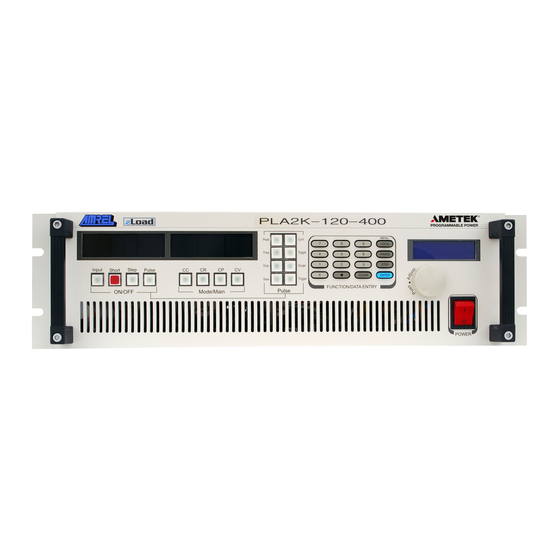
PLA 2U MODEL 19 18 FIGURE 1.8 – PLA 2U FRONT PANEL Note: Please refer to the Specifications for detailed unit dimensions Front Panel Descriptions 1. Input ON/OFF Button 12. Single Pulse / Power Interruption Transient 2. Short ON/OFF Button Operation Selection 3. -
Page 38: Figure 1.9 – Pla 2U Rear Panel
FIGURE 1.9 – PLA 2U REAR PANEL 30 27 Rear Panel Descriptions 23. ( + ) Positive input terminal. (one M10 screw thread) 24. ( – ) Negative input terminal. (one M10 screw thread) 25. Relay connector. RY_NC Dry Contacts alarm: a fault alarm is declared if there is a loss of AC power or protections are triggered. -
Page 39: Pla 3U Model
PLA 3U MODEL FIGURE 1.10 – PLA 3U FRONT PANEL NOTE: All front panel descriptions are the same for 2U, 3U, 4U, and 6U. see Figure 1.8. FIGURE 1.11 – PLA 3U REAR PANEL 1. ( – ) Negative input terminal. (one M10 ,two M6 screw threads) 2. - Page 40 input of the unit. Once RI is activated, it will turn off the dc output. In order to re -activate the unit, the connection between common and RI pin needs to be open again, and it will have 3 seconds delay. External programming port.
-
Page 41: Plw 4U Model
PLW 4U MODEL Note: Please refer to the Specifications for detailed unit dimensions FIGURE 1.12 – PLW 4U FRONT PANEL NOTE: All front panel descriptions are the same for 2U and 4U. FIGURE 1.12 – PLW 4U REAR PANEL Note: Please refer to the Specifications for detailed unit dimensions M470039-01 REV-F Page 40... - Page 42 1. ( – ) Negative input terminal. (two M12 screw threads) 2. ( + ) Positive input terminal. (two M12 screw threads) 3. Relay connector. a. RY_NC Dry Contacts alarm: a fault alarm is declared if there is a loss of AC power or protections are triggered.
-
Page 43: Pla 4U And 6U Model
PLA 4U AND 6U MODEL FIGURE 1.14 – PLA 4U FRONT PANEL NOTE: All front panel descriptions are the same for 2U, 3U, 4U and 6U. FIGURE 1.15 – PLA 4U REAR PANEL Note: Please refer to the Specifications for detailed unit dimensions 1. - Page 44 RY_CO Relay Common. Provides the common (reference) connection only for RY_NC or RY_NO RY_NO Dry Contacts alarm: a fault alarm is declared if there is a loss of AC power or protections are triggered. The fault alarm outputs provide a normally open relay configuration that provides user’s flexibility and isolation required to an external controller or an external alarm panel.
-
Page 45: Two: Installation
TWO: INSTALLATION INTRODUCTION This section provides recommendations and procedures for inspecting, installing, and testing the electronic load. BASIC SETUP PROCEDURE Use Table 2.1 to summarize the basic setup procedure and an overall v iew of the subsections. Use the procedure as a quick reference if you are familiar with the installation requirements for the programming electronic load. -
Page 46: Returning Electronic Load To The Manufacturer
Return Material Authorization Policy for warranty and non -warranty service: Before returning a product directly to AMETEK Programmable Power Inc. you must obtain a Return Material Authorization (RMA) number and the correct manufactory Ship To: address. Products must also be shipped prepaid. -
Page 47: Location, Mounting, And Ventilation
If the fuse is suspected to be defective, it should be inspected and, if necessary, replaced. To inspect or replace the fuse , please contact to AMETEK Programmable Power service department before performing the following steps: Disconnect the AC line cord from the unit to reduce electrical shock hazard. -
Page 48: Ac Input Power Connection
Model Type Fuse Rating Specification Location PLW6K 2.5A/250V Slow Blow External Fuse (Beneath the AC receptacle) PLW9K 4A/250V Slow Blow External Fuse (Beneath the AC receptacle) PLW12K 4A/250V Slow Blow External Fuse (Beneath the AC receptacle) PLW18K 4A/250V Slow Blow External Fuse (Beneath the AC receptacle) PLW24K 6.3A/250V... -
Page 49: Ac Input Cord
AC INPUT CORD WARNING JJJJJJ The AC input cord is the disconnect device for the electronic load. T he plug must be readily identifiable to the operator. The input cord must be no longer than 3 m (9.84 feet). The AC input cord we recommend is specified in Table 2.3, “AC Cord Specification”. If you require a special cord, call our sales representative. -
Page 50: Rear Panel Inlet & Outlet Pipe Installation
REAR PANEL INLET AND OUTPUT PIPE INSTALLATION (For PLW Rack/Cabinet Only) Inlet Outlet Pressure Drain Release For PLW models greater than 4U height, unit will be ship in a cabinet with a pre-installed manifold system. Rear Panel diagram above illustrates positions of the cooling water inlet and outlet pipe as well as the drain faucet and pressure release faucet. -
Page 51: Recommended Water Piping Installation For Plw Series
RECOMMENDED WATER PIPING INSTALLATION FOR PLW SERIES Water Switch – A 150 micron filter Pressure Meter INLET WATER PLW Series OUTLET WATER Water Switch – B Flow Meter FIGURE 2.2 PIPING AND COOLANT INSTALLATION Important Precautions: PLW height Pipe Size 3/8”... -
Page 52: Coolant With Anti-Freeze (Glycol) Precautions
COOLANT WITH ANTI-FREEZE (GLYCOL) PRECAUTIONS Cooling liquids containing Anti-Freeze (Glycol) will decrease the thermal efficiency of the PLW cooling system by reducing the cooling efficiency and increasing the viscosity of the coolant. To counteract the lowered heat dissipation, the GPM must be increased to maintain proper cooling of the system (refer to specific PLW model datasheet for requirement). -
Page 53: Load Wiring Length For Operation With Sense Lines
LOAD WIRING LENGTH FOR OPERATION WITH SENSE LINES For applications that use remote sensing, you must limit the voltage drop across each source line. We recommend that you use the larger load wirin g or ensure a smaller voltage d rop (1V typical max.) a long the wire, although the remote sensing will compensate for voltage drops up to 1% of V in each line. -
Page 54: Input Terminal Connector
INPUT TERMINAL CONNECTOR WARNING JJJJJJ There is a shock hazard at the load when using an electronic load with a rated output greater than 40V. To protect personnel against contact with hazardous voltages, ensure that the load, including connections, has no live parts, which are accessible. -
Page 55: Remote Sense Configuration
REMOTE SENSE CONFIGURATION CAUTION Turn off the electronic load before making any connections on the rear panel terminal block. In remote sense operation, the electronic load senses the input at output terminals of the source. As shown in figure 2 .4, the remote sense terminals of the Load are connected to the output of the source. -
Page 56: Trigger Operation
PROGRAMMING ELECTRONIC LOAD – DC Power Supply PROGRAMMING ELECTRONIC LOAD – FIGURE 2.5 PARALLEL CONFIGURATION TRIGGER OPERATION Figure 2.5 depicts the method of triggering the Electronic Loads. The TRIGOUT signal of the Electronic Load is connected to the Trigger input of the DMM. Additional instruments can be daisy chained to a DMM in the same manner. Once the preset settings of the instruments have been programmed, one trigger signal can simultaneously set all instruments to their transient settings. -
Page 57: Zero-Volt Loading Connection
OSCILLOSCOPE Programming Electronic Load (Trig-in) Pin – 10 at External Programming Port (Trig-out) Pin – 11 at External Programming Port XT in XT out – Input + XT out XT in – DEVICE UNDER TEST FIGURE 2.6 TRIGGER CONFIGURATION ZERO-VOLT LOADING CONNECTION The Electronic Load can be connected in series with voltage sources that can accommodate the minimum operating voltage and line voltage drop so the Electronic Load can test the devices at its full cu rrent capacity down to a zero -volt level. -
Page 58: Three: Local Operation
THREE: LOCAL OPERATION INTRODUCTION The programmable electronic load provides powerful control capabilit ies, wh ich consist of four operating modes CV/CC/CR/CP. To complement and enhance these features, an internal transient generator is provided to simulate dynamic operations. The Transient operation provides three programmable features, Transient frequency, Transient duty cycle, and Transient slew rate. -
Page 59: Local And Gpib Operation Information
WARNING Do not deliberately try to trip the OVP circuit on when performing battery-testing applications. When an Over- voltage condition occurs, the electronic load will try to sink more current in order to drop the input voltage source. In other words, the input source is supplying more power than the electronic load is capable of handling. By trying to trip the Over-voltage circuit, you may severely damage both the input source and the load. -
Page 60: Main Level Local Operation
MAIN LEVEL LOCAL OPERATION There are three levels of operations: MAIN level, TRANSIENT level and TRIGGERED level. The M AIN level operation and its associated set of values are for static operation. TRANSIENT and TRIGGERED operations are for various types of dynamic applications. -
Page 61: Encoder Operation
ENCODER OPERATION ENCODER BUTTON or SETTING ACTION FUNCTION Main Level Setting Press & Hold Change Input Value Screen in Main Value Change Decimal Position Edit Mode Rotate Lef t Decrement Value Rotate Right Increment Value Main Level Setting Press & Hold Modif y/Enter Value Screen With Input On Modif y/Enter Value... -
Page 62: Menu Function
MENU FUNCTION The MENU function allows the user to set the d ifferent system configurations such as GPIB, Stepping, Max/Min setting, Protection, and Calibration. The vast array of features and configurations allow the eLoad to accommodate different situations or testing configurations. The Local/Menu function is the start of the tree structure, which enables the user to branch. - Page 63 MAX VOLTAGE--------press ENTER key, input the maximum voltage then press ENTER MIN VOLTAGE ---------press ENTER key, input the minimum voltage then press ENTER. MAX CURRENT--------press ENTER key, input the maximum current then press ENTER. MIN CURREN-----------press ENTER key, input the minimum current then press ENTER. MAX RESISTANCE----press ENTER key, input the maximum resista nce then press ENTER MIN RESISTANCE-----press ENTER key, input the minimum resistance then press ENTER MAX POWER----------- press ENTER key, input the maximum power then press ENTER...
-
Page 64: Load Control Menu
ENTER key. GPIB/ETHER/USB should be display according to customer’s order. 2. INTERFACE------ 3. CODE-------------- press ENTER key, Input the code from AMETEK, then press ENTER. LOAD CONTROL MENU STEP PARAMETERS Selects the number of Step Count (0 - 65535 & infinity) and the different Step Modes (STEP, STEP AUTO, and STEP... -
Page 65: External Control
EXTERNAL CONTROL Basic Functionality: The external control function allows the eLOAD’s maximum range (L/M/H) voltage, current, power and resistance to be scaled from 0 to 10 Volts. The external voltage signal will control the eLOAD to operate at the corresponding current/voltage/resistance/power. -
Page 66: Short Control
SHORT CONTROL Enables/Disables Short Control. CROSS MODE Toggles between Input Off/Input Remain. Input remain will allow input to remain on when switching modes. CROSS RANGE Toggles between Input Off/Input Remain. Input remain will allow input to remain on when switching ranges. TRIGGER SOURCE Select the trigger source for transient operation. -
Page 67: Max/Min Setting Function
recommendation for improved performance without changing the turn -on sequence, the V-On threshold can be increased to a voltage closer to the application’s operating voltage and the V-On detection mode changed to “Continuous”. By making the necessary adjustments, both the DUT and eLOAD can operate under stable conditions to avoid irregular results. -
Page 68: Boot Input
BOOT INPUT Boot Input allows the input to be automatically turned on once the unit is powered on. By default, Boot Input is deactivated. LOAD PROFILE MENU The profile menu allows 4 different profiles (0~3) to save all current load configurations. As a factory default, profile 0 &... -
Page 69: Rs-232 Function
to increase or decrease the GPIB address, then press the “ENTER” key to confirm the value. The number displayed " annunciated behind it is the currently selected GPIB address. Press the “CLEAR” to escape the Primary ◄ with the " ADDR mode. - Page 70 2) eLoad IP address: ___ . ___ . ___ . ___ 3) Gateway IP address: ___ . ___ . ___ . ___ 4) Subnet mask: ___ . ___ . ___ . ___ Setting the eLoad Ethernet Parameters You need to set the eLoad Ethernet IP address first. The eLoad IP address uniquely identifies the load to other devices on the network, and is required for the eLoad to communicate over the network.
-
Page 71: Usb Function
To Exit, press LOCAL to go back to the start-up screen The Ethernet Port Number is 3000. Please contact AMETEK Programmable Power Technical Support for any additional Ethernet Set -up Question. USB FUNCTION The eLoad also provides a USB remote interface to connect to your computer. You need to install USB driver included in a CD-ROM shipped with your eLoad . - Page 72 4) Select the “install from a list or specific location [Advanced]” radio button and click next to continue 5) Select the “Search for the best driver in these locations.” Radio (default) and check only the “search removable media [floppy, CD-ROM…]” checkbox. M470039-01 REV-F Page 71...
- Page 73 6) Click next 7) The Wizard will search for the needed drivers 8) After the driver has been found, the wizard will display the “completing the Found New Hardware Wizard” screen M470039-01 REV-F Page 72...
- Page 74 9) Click finish to complete USB driver installation 10) A pop-up balloon will notify you that the USB Serial Device is ready for use Windows 2000 USB Driver Installation Procedures 1) Connect eLoad using USB cable 2) A new hardware will be detected M470039-01 REV-F Page 73...
- Page 75 3) The “Found New Hardware Wizard” screen will appear 4) Click Next to continue 5) Select the “Search for suitable driver for my device (recommended)” to search for the appropriate driver 6) Click Next to continue M470039-01 REV-F Page 74...
- Page 76 he driver files are located in the pre-packaged CD 8) Check the “Specify a location” check box and click Next to continue 9) Select the drive corresponding to your CD-ROM, and locate the folder name “FT245VCP driver 2104 XP certified” 10) Click OK to continue M470039-01 REV-F Page 75...
- Page 77 11) The correct driver has been located, click Next to continue installation 12) Windows will check for the validity of the device driver, click Yes to continue installation M470039-01 REV-F Page 76...
- Page 78 13) Windows will copy the needed drivers to the PC 14) The above screen will appear to notify the end of the installation process and the USB Serial Port will now function properly. 15) Click Finish to complete setup Windows 98 USB Driver Installation Procedures 1) Connect eLoad Unit using USB cable M470039-01 REV-F Page 77...
- Page 79 A new hardware will be detected 2) The “Add New Hardware Wizard” window will appear 3) Click next to continue 4) Select the “Search for the best driver for your device.” radio button, and click Next to continue M470039-01 REV-F Page 78...
- Page 80 5) Check the “Specify a location” check box and browse to select the file “FT245 VCP driver 2104 XP certified” from your CD-ROM drive 6) Click Next to continue 7) Now the location of the driver has been set, and click next to install the driver M470039-01 REV-F Page 79...
- Page 81 8) Click Cancel and the wizard will automatically locate the needed driver 9) The drivers have been installed successfully, and now the High Speed Serial Converter will work properly 10) Click Finish to complete the installation process Verify Installed USB Driver using Hyper-Terminal (Windows XP/2000/98) 1) Enter into Device Manager window 2) Locate and record the “USB Serial Port”...
-
Page 82: Authenticate Menu
AUTHENTICATION MENU SERIAL NUMBER Displays the serial number/MAC Address of the eLoad unit INTERFACE Displays the interfaces activated for the load unit CODE Field Upgradeable E-Package (Ethernet +USB) code activation; Please contact factory with serial number/MAC Address to obtain further information. TRANSIENT OPERATION The AMREL Programmable Electronic Load can facilitate testing sources and load simulation through the use of its internal transient generator. -
Page 83: Entering Transient Mode Values
ENTERING TRANSIENT MODE VALUES Example: The test application requires the main operation to be at 25 A in CC mode and a Transient test current of 50.0 A, Frequency of 500Hz, Slew rate of 5 ms, and a 50% Duty cycle. Set the Transient operation mode to Continuous by pressing the CONT Hot Key. -
Page 84: Local Transient Operation
LOCAL TRANSIENT OPERATION LCL Operation: STEP Selection MENU/LOCAL → LOAD CONTROL → STEP PARAM. →STEP →STEP AUTO →STEP ONCE OTHER TRANSIENT OPERATION SELECTIONS Remote Only – Trigger Operation CONT Hot Key – Continuous Operation TOGGLE Hot Key – Toggle Operation SINGLE Hot Key –... -
Page 85: Toggle Mode
TOGGLE MODE: In toggle mode, the eLoad input alternates between two user-defined input levels. Unlike transient-continuous mode, the input only changes from one level to another, one transition at a time. Transient Level Toggle Main Level Typical Application: Testing the transient recovery time for a CV power supply. The recovery time for a power supply is defined as the time required for the supply to settle to a predefined settling band following a change in load current caused by an induced tra nsient (pulse). -
Page 86: Pulse Mode
PULSE MODE: In pulse mode, the eLoad generates a pulse with a user-defined amplitude and width. The pulse width can be set from 0.5 ms to 10 seconds. Transient Level Main Level Pulse Width Typical Application: Testin g the transient recovery time for a CV power supply. The recovery time for a power supply is defined as the time required for the supply to settle to a predefined settling band following a change in load current caused by an induced transient (pulse). -
Page 87: Trigger Mode
TRIGGER MODE In trigger mode, the eLoad waits for a trigger signal from the selected trigger source (HOLD (local), BUS, EXTERNAL and to switch to the user configured trigger level. The trigger level can be set to a value greater or less than the ETHERNET) main value. -
Page 88: Step Mode
STEP MODE In step mode, the eLoad generates customized sequence of different input levels up to a maximum of 256 steps (points) for each mode, with dwell times from 1ms to 65535 ms. The step sequence can be cycled for one up to 65535 count(s) or infinity for unlimited repeat. -
Page 89: Step Function
STEP FUNCTION The eLoad provides 256 points for self-pro gramming capability for which parameters can be programmed in the Menu function. This feature allows the users to create a mini program and automate the control of the eLoad without the need of computer, GPIB, USB, ETHERNET or RS -232 communication interface. - Page 90 Set the STEP Count – Scroll usin g the encoder for the total number of times the steps will be processed via the Menu → Load Control → Step Param. → Count Set first step value - Press the CC hot key, press the STEP key to enter step edit mode, scroll to select step 1. Press the STEP key to switch between step value and time settings.
-
Page 91: Four: Remote Operation
FOUR: REMOTE OPERATION INTRODUCTION The Programming Electronic Load is provided with GPIB and RS-232 Standard Commands for Programmable Instruments (SCPI) interface for automated testing applications. The purpose of this section is to introduce the user to SCPI commands used to control the eLoad via remote communication. NOTE: For a more comprehensive set of SCPI COMMANDS, please refer to the Programming Manual. -
Page 92: Syntax Overview
SYNTAX OVERVIEW Use of the Colon (:) A co lon is used to separate command mnemonics. It indicates a move down in branch level of the command tree. The command follows a colon is a sub command of the command immediate before the colon. When colon precedes the first command mnemonic of a message unit, it becomes root specifier. -
Page 93: Scpi (Gpib & Rs-232) Command Set
SCPI commands should adhere to their syntax and format structure (command line) in order to be properly process by the electronic load. Query commands request measured values, status, or programmed settings from the electronic load. System commands belong to the GPIB bus system commands list to controls GPIB bus condition and electronic load interface system. - Page 94 Parameter: 0 to maximum value; MIN; MAX Units: Amp. “CURR:PROT:UND 1.5”- sets the undercurrent protection to 1.5 Amps. Example: CURR:PROT:UND:DEL This command sets the delay time for under-current protection. When the input current falls belo w the undercurrent protection limit for the programmed delay period, the load input is off and draws no current. Parameter: 0 to maximum value Units: ms...
- Page 95 “CURR:LIM:MIN 50” – sets minimum current input level to 50Amps Example: Resistance Programming Functions RESistance This subsystem programs the constant resistance mode functions of the Electronic Load. The IEEE488.1 command, “RSET” and “SET” (if current active mode is CR mode), can also be used. This command sets the input resistance level that is to be applied immediately in the constant resistance mode.
- Page 96 “RES:LIM:MAX 50” – sets maximum resistance input level to 50 Ohms. Example: RES:LIM:MIN This command sets and queries the minimum input resistance level that is to be applied immediately in the CR mode. Parameter: 0 to maximum value; MIN; MAX Units: Ohm.
- Page 97 transient voltage level is belo w the main voltage level, the switching will not occur until the main leve l is below the value of VOLT:TLEV. The IEEE488.1 command, “VTR” can also be used. Parameter: 0 to maximum value; MIN; MAX Unit: Volt “VOLT: TLEV 50”...
- Page 98 Parameter: 0 to maximum value Units: ms. “POW:PROT:OVER:DEL 1200”- sets the overpower protection delay time to 1200 ms. Example: POW:PROT:UND This command sets an under power protection limit to the input power that the Electronic Load accepts. When the input power falls below the under power protection limit for the programmed dela y period, the load input is off.
- Page 99 POW:LIM:MIN This command sets and queries the minimum input power level that is to be applied immediately in the constant powe r mode. Parameter: 0 to maximum value; MIN; MAX Units: Watt. “POW:LIM:MIN 50” – sets minimum power input level to 50 Watts. Example: INPut/OUTPut Input Programming Functions This subsystem controls the Electronic Load input.
- Page 100 MODE CP or MODE:POW This command sets Electronic Load to constant power mode. MODe:RANGe This command sets the range after the mode is set. 0 – 3 Parameters: i. low range ii. middle range iii. high range iv. ultra-range “MODE:RES” – sets the Electronic Load in CR mode; Example: “MODE:RANG 2”...
- Page 101 UTIL:STEP:LOOP This command sets the number of loops the stepping operation will repeat. Parameter: 0 to 99 “UTIL:STEP:LOOP 10” - sets the number of loops to 10. Example: If Parameter is set to 0, the loops will repeat indefinitely. UTIL:STEP:COUNT This command sets the number of steps activated Parameter: 1 to 99...
-
Page 102: Common Commands
UTIL:RANG 0 – Sets the electronic load to manual range. Example: SYST:RANG? This command returns the number of ranges for each mode in a “CV/CC/CR/CP” sequence . SYST:RANG? – returns “1/2/3/2” means 1 range for CV mode, 2 ranges for CC mode, 3 Example: ranges for CR mode and 2 ranges for CP mode. -
Page 103: Command List
COMMAND LIST COMMAND FORMAT ACTION INPUT enable INP[?] 0/1/OFF/ON INP[:STAT][?] 0/1/OFF/ON SHORT enable SHOR 0/1/OFF/ON INP:SHOR[:STAT][?] 0/1/OFF/ON SET commands SET value SET[?] MAX/MIN SET Voltage VSET[?] MAX/MIN VOLT[:LEV][:IMM][?] MAX/MIN VOLT[:LEV]:TRIG[?] MAX/MIN SET Current ISET[?] MAX/MIN CURR[:LEV][:IMM][?] MAX/MIN CURR[:LEV]:TRIG[?] MAX/MIN SET Resistance RSET[?] MAX/MIN RES[:LEV][:IMM][?]... - Page 104 PROTECTION commands OVER Voltage value VOLT:PROT:OVER[?] OVER Current value CURR:PROT:OVER:[?] OVER Power value POW:PROT:OVER:[?] UNDER Voltage value VOLT:PROT:UND[?] UNDER Current value CURR:PROT:UND[?] UNDER Power value POW:PROT:UND[?] OVER-V Time Delay VOLT:PROT:OVER:DEL[? OVER-C Time delay CURR:PROT:OVER:DEL[?] OVER-P Time delay POW:PROT:OVER:DEL[?] UNDER-V Time Delay VOLT:PROT:UND:DEL[?] UNDER-C Time delay CURR:PROT:UND:DEL[?]...
-
Page 105: Five: Calibration
FIVE: CALIBRATION INSTRUCTION WARNING Exercise caution when using and calibrating an electronic load. High energy levels can be stored a t the input voltage terminals on an electronic load in normal operation. In addition, potentially lethal voltages exist in the power circuit and on the input and sense connectors of a power supply with a rated output greater t han 40V. -
Page 106: Calibration Configuration
CALIBRATION CONFIGURATION There are two configurations for the calibration of the electronic load. One is for measuring voltage and the other for measuring current. INPUT − (VOLTAGE − 0.01 (CURRENT CURRENT SHUNT − POWER SUPPLY FIGURE 5.1 – CALIBRATION SETUP CONFIGURATION CALIBRATION PARAMETERS The following are the parameters that are calibrated. -
Page 107: Local Calibration Procedures
LOCAL CALIBRATION PROCEDURES The eLoad uses the two point’s calibration method whereby the eLoad has two preset calibration points for each parameter. The microprocessor does the calculation for the operating slope and offset in programming and readback functions. The default calibration points are low point 6400 count and high point 32000 count. These are the default bit counts (DAC circuit) where the 6400 counts point represents approximately 10% of full scale and the 32000 counts point is at 50% full scale. - Page 108 Use “” and “” until you see MAIN CC0 parameter. Press enter: CNT: Input measured voltage from Curr.DMM, then press ENTER. Input measured voltage from Curr.DMM then press ENTER key. A “SUCCESS” message HI = CNT: should be display on the front panel LCD. Press “”...
- Page 109 Use “” and “” until you see MAIN CR2 parameter. Press enter: LO= CNT: Input measured voltage from Volt.DMM, then press ENTER. LO= CNT: Input measured voltage from Curr.DMM, then press ENTER. HI= CNT: Input measured voltage from Volt.DMM, then press ENTER. Input measured voltage from Curr.DMM then press ENTER key.
- Page 110 should be display on the front panel LCD. Press “” to select TRAN CV2. Then press enter. CNT: Input measured voltage from Volt.DMM, then press ENTER Input measured voltage from Volt.DMM then press ENTER key. A “SUCCESS” message HI = CNT: should be display on the front panel LCD.
- Page 111 LO= CNT: Input measured voltage from Curr.DMM, then press ENTER. HI= CNT: Input measured voltage from Volt.DMM, then press ENTER. Input measured voltage from Curr.DMM then press ENTER key. A “SUCCESS” message HI= CNT: should be display on the front panel LCD. CR HIGH RANGE TRANSIENT LEVEL CALIBRATION CR high range transient level calibration requires a power supply that has high voltage and medium current, but operator has to estimate the power consumption of load.
- Page 112 CV READBACK LEVEL CALIBRATION CV readback main level calibration requires a power supply that co vers full range of input voltage of load and is capable of operating in CV and CC mode. Estimate the power consumption of load, because power supply will go to CC mode while calibrating the load.
-
Page 113: Re-Installing Calibration Data
First you need to read the slope and offset values from the electronic load when you receive the unit, or you can call AMETEK Programmable Power Inc to get the calibration information for the electronic load (need serial number) -
Page 114: Six: New Eload Features
SIX: NEW ELOAD FEATURES NEW ELOAD FEATURES FW: 2.17/060216 • Power Interruption (Current Interruption) FW: 2.29/061005 • Under-temperature Trip Caution Message (UTT) • Input Contactor Control • Ultra-low Range Option FW: 2.40/061005 • Step Modification • OSC Range Selection FW: 2.49/081007 •... -
Page 115: Under Temperature Warning
Proceed testing with caution to ensure the UTT message does not continue. If message still occurs, please contact AMETEK Technical Support. Local Control NONE... - Page 116 Typical eLoad Turn-on Sequence 1) Close External Contactor/Relay 2) DUT output On (During Delay) 3) eLoad input On Typical eLoad Turn-off Sequence 1) eLoad input Off 2) DUT Output Off (During Delay) 3) Open External Contactor/Relay Local Control MENU ➔LOAD CONTROL➔ INPUT CONTACTOR ➔...
- Page 117 Constant Power Ultra Low (CPUL) Range – • Programming Accuracy: 1% of Setting + .1% of CPUL Max Power • Read back and Measurement: .05% of Reading + .1% of CPUL Max Power • Resolution: 14 Bits Constant Resistance Ultra High (CRUH) Range – •...
-
Page 118: Step Mode Modification
5. Step Mode Modification The Step Operation for the eLoad has been modified to provide 256 set points for the step operation. In the older version firmware, the 256 set points are separated into 4 profiles of 256 steps, which limited the amount of total programmable step set points. - Page 119 Step Remote Operation Step Programming Functions STEP This subsystem programs the stepping functions for stepping mode. The number of loops, step values, and dwell t imes are programmed for a specified operating mode. [SOURce:]STEP:COUNt This command sets the number of times that the STEP is executed before it is completed. The command accepts parameters in the range 1 through 65535, or infinity (0).
-
Page 120: Osc Range Selection
■ ONCE Causes the STEP to advance only one point after each trigger. Triggers that arrive during a dwell delay are ignored ■ AUTO Causes the entire STEP to be executed sequentially after the starting trigger, paced by its dwell delays. As each dwell delay elapses, the next point is immediately executed. Command Syntax STEP:CURRent:STATe <NR1>... -
Page 121: Interlock Function
Remote Programming SYSTem:OSCillate:PROTection This command selects the Bandwidth (selects the programmable slew rate range) of the eLoad and enables/disables Oscillation Protection. Command Syntax SYST:OSC:PROT <OSC mode> Parameters <OSC Mode> 0: DEFAULT 1: OSC1 2: OSC2 3: OSC3 4: DEFAULT + disabled 5: OSC1 + disabled 6: OSC2 + disabled 7: OSC3 + disabled... -
Page 122: Step Time Unit
8. STEP TIME UNIT This function allows user to select the step time base unit from millisecond to second, which enhanced the maximum dwell time (step time) from 65535ms to 65535s per step point. Up to 256 step points are user programmable. -
Page 123: 10. Pv Sweep Function
10. PV SWEEP Function Sweep feature for PV test. Please refer to the descriptions below for details of Sweep operation on eLoad devices. * A graphical PC Software for ELOAD Sweep control is available online for download. 1. SCPI commands Description: enter/leave sweep operation mode. - Page 124 Description: the last value for sweep step. Usage: SWE[EP]:STOP:VAL[UE] <stop value> SWE[EP]:STOP:VAL[UE]? <stop value>: value between 0 and max. value of mode. NOTE: 1. stop value MUST NOT be the same as start value , or "ERR 2" message will display on front panel while launching sweep operation, and sweep state code will be -2 (while query by SWE:STAT?) Description: the first value for sweep step.
- Page 125 Description: query data record sampled in sweep operation Usage: SWE[EP]:DATA:VAL[UE]? <record number> <record number> - value between 1 and number got by "SWEEP:DATA:COUNT?" response format: <set value> <measured voltage> <measured current> <set value> - value set for this step <measured voltage> - voltage measured in this step <measured current>...
- Page 126 FF: fill factor in % Pm: max. power value Voc: measured voltage of open-circuit test Isc: measured current of short-circuit test Vmp: measured voltage at max. power step. Imp: measured current at max. power step. 3. Front panel operation for PLA/PLW new front panel a.
-
Page 127: 11. Master-Slave Parallel Operation
11. Master-Slave Parallel Operation The eLoad provides Master/Slave configuration at all modes with current sharing capability. Please refer to the steps below for eLoad configuration and control. Available Mode Ranges * CC Mode High Range * CP Mode High Range * CR Mode Low Range * CV Mode Low Range * CV Mode Mid-Range... - Page 128 More devices can be paralleled by daisy chain the Trig_Out of each unit to the Trig_In of the other unit for digital control signal and by connecting the IMON of the Master unit to the EXT_PRG of the Slave units for analog control signal.
- Page 129 9) Saving the Configuration: Menu → PROFILE → RESET→ Enter to update the operating Min/Max ranges (It needs to reset again once changed back to Master only) eLoad Configuration – Slave eLoad 1) Manual Range Control: RANGE → MANUAL High only NOTE: It should be high range only in order to have same current setting controlled by IMON from Master unit.
- Page 130 System Spec with the same models in parallel N =Number of Slave + 1, P=Power rating of Master, I=Current rating of Master, R=Resistance rating of Master, S=Slew time of Master should be less than the slew time of Slave Psystem=P x N Isysetm=I x N Rsysetm=R/N Ssystem-min=S x N if Master slew-time=Slave slew-time...
-
Page 131: Remote Inhibit
REMOTE INHIBIT (RI) & DRY CONTACTS ALARM PIN DEFINITION In the case of fault conditions, the eLoad provides an externally short-activated emergency shut-off port (Remote Inhibit) that will disengage the eLoad operation. For added protection, normal and deviant conditions can be identified by the Dry Contacts Alarm, which utilizes Normal Open (RY_NO) and Normal Close (RY_NC) relays as alarm indicators for customization of external protection systems. -
Page 132: Seven: Specification And Power Curve
SEVEN: SPECIFICATION AND POWER CURVE COMMON SPECIFICATIONS M470039-01 REV-F Page 131... - Page 133 1 – All Mode Specification measure by slow band and 25ºC room temperature unless otherwise specified 2 – Transient Mode Specification must be x2 – lease contact AMETEK Technical Support for a full detail datasheet / power curve for a specific eLoad model. M470039-01 REV-F Page 132...
-
Page 134: Pla Power Curves
PLA Model Weight [lbs] Dimension WxHxL [inch] PLA800 19.5x17x3.50 PLA1.5K 19.5x17x3.50 PLA2K 24.5x17x5.25 PLA2.5K 24.5x17x5.25 PLA3K 24.5x17x5.25 PLA4K 24.5x17x7.00 PLA5K 24.5x17x7.00 PLA6K 24.5x17x10.5 PLA7.5K 24.5x17x10.5 ≈105 – dual boxes 24.5x17x7.00 –dual boxes PLA10K ≈135 – dual boxes 24.5x17x10.5 –dual boxes PLA15K ≈120 15U Cabinet... -
Page 135: Plw Power Curves
PLW Model Weight [lbs] Dimension WxHxL [inch] PLW6K 27.5x17x3.5 PLW9K 27.5x17x3.5 PLW12K 27.5x17x3.5 PLW18K 27.5x17x3.5 PLW24K 27.5x17x7.0 PLW36K 27.5x17x7.0 PLW POWER CURVES M470039-01 REV-F Page 134... -
Page 136: Appendix A: Pel & Pla/Plw Command Compatibility Table
APPENDIX A: PEL & PLA/PLW COMMAND COMPATIBILITY TABLE PEL & PLA/PLW Driver Compatibility Configuration For PEL and PLA/PLW driver compatibility, the following procedures are needed. 1. Power on unit 2. Utility → Profile → Recall → 1 3. Recall profile 1 4. - Page 137 PEL & PLA/PLW PROGRAMMING COMMAND COMPATIBILITY CHART PLA & PLW PEL Syntax & PLA Syntax & PEL COMMANDS COMMANDS Parameters Parameters INP[?] INP[?] INP[:STAT][?] INP[:STAT][?] SHOR SHOR INP:SHOR[:STAT][?] INP:SHOR[:STAT][?] SET[?] SET[?] VSET[?] VSET[?] VOLT[:LEV][:IMM][?] VOLT[:LEV][:IMM][?] VOLT[:LEV]:TRIG[?] VOLT[:LEV]:TRIG[?] ISET[?] ISET[?] CURR[:LEV][:IMM][?] CURR[:LEV][:IMM][?] CURR[:LEV]:TRIG[?] CURR[:LEV]:TRIG[?]...
- Page 138 PEL Duty Range: PLA/PLW/LPL Duty DUTY[?] DUTY[?] 2~98 Range 0~100 VOLT:DUTY[?] VOLT:DUTY[?] CURR:DUTY[?] CURR:DUTY[?] RES:DUTY[?] RES:DUTY[?] POW:DUTY[?] POW:DUTY[?] LPL/PLW/PLA Frequency Range: 0.1 PEL Frequency FREQ[?] FREQ[?] ~ N kHz (N; Range: 0.1 ~ 20 kHz maximum range value will vary by model) VOLT:FREQ[?] VOLT:FREQ[?] CURR:FREQ[?]...
- Page 139 MODe:RANGe <n> MODe:RANGe <n> MODe:RANGe? <MODE> MODe:RANGe? <MODE> SYST:RANGe[?] SYST:RANGe[?] UTIL:STEP:LOOP[?] UTIL:STEP:LOOP[?] 0 (Infinity) ~ 99 0 (Infinity) ~ 65535 <VAL> <VAL> UTIL:STEP:COUNT[?] UTIL:STEP:COUNT[?] 1 ~ 99 1~256 <VAL> <VAL> Step Count - 0~99; Step Count - 1~256; STEP:TIME[?] <STEP STEP:TIME[?] <STEP VAL (Step Time) - 10 VAL (Step Time) - 0 ~...
-
Page 140: Appendix B: Plw - Cooling System Guideline
20°C 20°C PLW12K 10°C PLW48K 10°C 15°C 15°C 20°C 20°C PLW24K 10°C PLW60K 10°C 15°C 15°C 20°C 20°C AMETEK recommends installing a Water Flow Meter to Monitor GPM Flow 2) PLW HEATSINK TEMPERATURE VS GPM CURVES M470039-01 REV-F Page 139... - Page 141 M470039-01 REV-F Page 140...
- Page 142 3) Pressure Requirements: The Inlet Pressure or pressure differential should never exceed 70PSI. Please see below for additional precautions. A) Install a Pressure Regulator on the inlet end of the Water Cooling System. This will help regulate the inlet water pressure. The Honeywell DialSet® Pressure Regulating Valve is a good reference. B) There may be circumstances where the water valve is latched open due to excessive inlet pressure and GPM Flow.
- Page 143 C) As good practice, AMETEK Recommends the installation of inlet and outlet pressure meters to monitor the pressure differential in the system. The recommended operating temperature of the eLoad is between 36°C ~ 40°C and lower. The GPM and Inlet Pressure can be adjusted to maintain the eLoad operating temperature within this range. Use the front panel temperature display to MONITOR the heat sink temperature, go to (MENU→DISPLAY→METER...
- Page 144 F) AMREL recommends utilization of De-ionized/Distilled Water or non-corrosive coolants (pH level of G) Water Viscosity greater than 50 CST H) When installing the inlet and outlet pipes, be careful not to over-torque the male pipe fittings into the Inlet/Outlet pipe terminals. This additional force may crack the inlet and/or outlet female piping on the eLoad.
- Page 145 2) Unplug the 12V connector (4 pin), remove the hexagonal nut and take off the coil assembly. M470039-01 REV-F Page 144...
- Page 146 3) Remove the 4 screws securing the solenoid, and take off the solenoid assembly. M470039-01 REV-F Page 145...
- Page 147 4) Locate the black rubber diaphragm, and remove it. (Do not forcefully remove the rubber diaphragm, it could be permanently damaged). After removing the solenoid valve assembly from the PLW unit, look for any residue or sediments that may be clogging the system, and ensure there are no build -ups around the internal components.
- Page 148 5) Ensure rubber diaphragm has an air-tight fit with the piping system, and connect the solenoid assembly back into place. 6) Fasten the screws slowly to make sure the four corners are balanced to prevent a leakage. 7) Place the coil assembly over the solenoid and re-bolt it tightly. M470039-01 REV-F Page 147...
- Page 149 8) Now the rubber diaphragm has been replaced and the load is ready for operation. Possible Failure Symptoms For PLW loads, due to slight solenoid valve factory imperfections or improper usage, the rubber diaphragm of the water valve may tear after some usage and create a pressure leak. The result will cause a loud vibration sound, when the water valve is trying to turn on, due to the pressure leak, the valve will be unable to open properly.
- Page 150 10) Inspect the rubber diaphragm to verify the defect/damage. Good 11) Contact AMREL Technical Support and report the defective valve. A replacement will be shipped shortly Tear 12) Replace the rubber diaphragm and reconnect it back with the metal solenoid assembly. Make sure the metal stub forms a snug fit with the rubber diaphragm groove (blue arrow).
- Page 151 7) MANIFOLD-4U / External piping kit installation for PLW. AMREL standalone 4U height Water-cooled eLoad unit is supplied with a coolant distribution kit. Due to the different cooling system requirements, the external piping kit is designed to convert two 3/8” NPT into one ½” NPT. To properly install the coolant distribution kit, please refer to the following directions carefully.
- Page 152 OUTLET BOTTOM interconnect pipe x 1pcs Plastic Round Shim ½”ID, ¾”OD, 0.003” Thick x 4 pcs M470039-01 REV-F Page 151...
- Page 153 Installation Procedures: Locate both the top and bottom FLUID INLET copper pipes. Locate both the top and bottom FLUID OUTLET copper pipes. Outlet top Inlet top Outlet bottom Inlet bottom Use pipe thread sealant PTFE tape wrap approximately 3 to 4 times around each pipe male threads of each interconnect pipe, to ensure a tight seal and to prevent leak.
- Page 154 *Recommended tools: adjustable ranch x 2pcs Install INLET TOP interconnect pipe to female threaded pipe at PLW rear panel. Install INLET BOTTOM interconnect pipe to female threaded pipe at PLW rear panel. Using one ranch fixed position on the female threaded pipe at PLW rear panel, and the other ranch torque carefully at the interconnect pipe, Tighten the male end connection into the mating female end connection until hand-tight approximately 2 threads.
- Page 155 Install OUTLET TOP interconnect pipe to female threaded pipe at PLW rear panel. Install OUTLET BOTTOM interconnect pipe to female threaded pipe at PLW rear panel. Using one ranch fixed position on the female threaded pipe at PLW rear panel, and the other ranch torque carefully at the interconnect pipe, Tighten the male end connection into the mating female end connection until hand-tight approximately 2 threads.
-
Page 156: Appendix C: Pv Sweep & Pv Operation Guide
APPENDIX C: PV SWEEP - PC Software Guide PV SWEEP & PV OPERATION GUIDE Revision History First release 1.0 Start Program When click on the icon, an interface selection window is pop-up to select communication interface between PC and device. Please turn the knob to select interface, and change the interface parameters, and click the button to launch interface communication. - Page 157 that voltage set point. Press button to launch sweep. While sweep is in operation, a message box will show sweep state at the center of Window, until a pop-up box notify sweep operation is done successfully or has failed. If sweep operation is done successfully, system automatically start data capture operation to retrieve sampled data from devices, and accordingly captured data will be prompted to save into hard drive in .csv file format, where data capture can also be done by pressing button.
- Page 158 I-V curve P-V curve (valid ONLY in PV mode) Device Identification and Version Information Device identification is serial number of device shown at the right side of control panel which look like , while version information is located at bottom of control panel and it look like , where “1.01”...
- Page 159 Profile Load & Save Proofed test cases can be saved to disk as a ,ini file for repeatedly accessing, which will backup/restore all parameters in Control Panel. Refer to File->Profile menu shown below. Descriptions of Meter, I-V Graph, and P-V Graph While Meter can be shown on desktop when system connect to device.
- Page 160 Description of P-V Graph In the P-V graph (see below), X axis define measured voltage value for each step, left Y axis define measured current value, and right Y axis define measured power value. The meanings for fields at the bottom of graph, Imax - maximum measured current.(@ at the right is its value of X axis) Imin - minimum measured current.(@ at the right is its value of X axis) Pmax - maximum measured power.(@ at the right is its value of X axis)
Need help?
Do you have a question about the Amrel PLA Series and is the answer not in the manual?
Questions and answers