
Related Manuals for JUMO 202550


Summary of Contents for JUMO 202550
- Page 1 Type 202550 µP indicator/controller analytical measurement B 20.2550.0 Operating Instructions 02.02/00403097...
-
Page 3: Table Of Contents
Preface ______________________________________________________________________ 4 Typographical conventions _____________________________________________ 5 Warning signs ________________________________________________________________ 5 Note signs ___________________________________________________________________ 5 Application ____________________________________________________________ 6 Type 202550 _________________________________________________________________ 6 Operating Instructions B 20.2550.0 ______________________________________________ 7 Instrument identification ________________________________________________ 8 Type designation ______________________________________________________________ 9 Instrument description ________________________________________________ 10... - Page 4 13.2 Analog inputs - C111 _________________________________________________________ 36 13.3 Electrode type - C112 ________________________________________________________ 37 13.4 Electrode monitoring - C114 ___________________________________________________ 37 13.5 nuLL - SLoP _________________________________________________________________ 38 13.6 Configuration parameter for general (not pH-specific) functions ____________________ 38 Redox indicator _______________________________________________________ 39 14.1 Redox measurement circuit ___________________________________________________ 39 14.2...
- Page 5 22.6 2-point calibration __________________________________________________________ 68 Operator level of the universal indicator ________________________________ 69 23.1 Settings _____________________________________________________________________ 69 Parameter level _______________________________________________________ 70 24.1 Settings _____________________________________________________________________ 70 Configuration level of the universal indicator ____________________________ 72 25.1 General _____________________________________________________________________ 72 25.2 Analog inputs - C111 _________________________________________________________ 72 25.3 Configuration parameter for general functions (not specific to the universal indicator) _ 73 25.4...
-
Page 6: General
1 General Preface Please read these Operating Instructions before commissioning the instrument. Keep the manual in a place that is accessible to all users at all times. Please assist us to improve these operating instructions, where necessary. Your suggestions will be welcome. Phone +49 661 6003-0 +49 661 6003-607 All necessary settings are described in this manual. -
Page 7: Typographical Conventions
2 Typographical conventions Warning signs Danger This symbol is used when there may be danger to personnel if the instructions are ignored or not followed correctly! Caution This symbol is used when there may be damage to equipment or data if the instructions are ignored or not followed correctly! Note signs Note... -
Page 8: Application
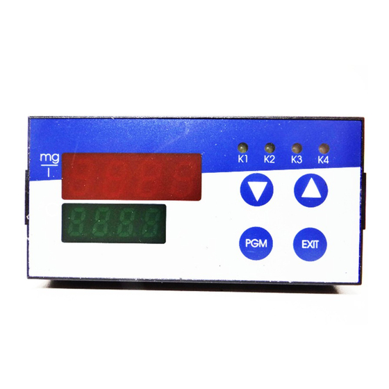
Examples of JUMO transmitters with standard output signals: - for dissolved oxygen JUMO dTRANS O2 01 - for free chlorine, chlorine dioxide and ozone JUMO Typ 202630 - JUMO pressure transmitters Display The instrument features two 4-digit 7-segment displays for indicating the main variable (red) and the temperature (green). -
Page 9: Operating Instructions B 20.2550.0
3.2 Operating Instructions B 20.2550.0 These operating instructions provide full instructions on the installation, electrical connection, commissioning, operation, parameter setting and configuration of the microprocessor indicator/controller for analytical measurement, type 202550. Layout of the These operating instructions are arranged as follows: operating... -
Page 10: Instrument Identification
4 Instrument identification Check for You should have received at least the following: completeness - Indicator/controller for analytical measurement, Type 202550 - 2 mounting brackets - Seal (housing/panel) - Operating Instructions B 20.2550.0 Nameplate The nameplate is glued to the housing. -
Page 11: Type Designation
.. - ... , ... , .. - .. - .. / ... Generally, the following configurations can be freely selected by the user on all instruments of the 202550 series: - Controller off - Limit controller - Pulse width controller with P, PI, PD, PID control action... -
Page 12: Instrument Description
5 Instrument description 5.1 Technical data Ω Analog Input resistance approx. 40 ≤ input 1 Deviation from characteristic: 0.5% of the measurement range 0(4) — 20 mA. Analog Pt100 or Pt1000 resistance thermometer, in 2-wire or 3-wire circuit, input 2 -50 to +250°C Measurement display in °C or °F (option) ≤... - Page 13 5 Instrument description Reference 25°C (for conductivity indicator/controller) temperature ≤ 0.15% of measurement range Deviation from characteristic Temperature -50 to +250°C (option °F) display Outputs 5 outputs are available: Output 1 / 2 Make contact (can also be configured as break contact) relay Contact rating: 3A, 250V AC, with resistive load...
- Page 14 5 Instrument description 5.1.1 General controller data A/D converter resolution > 15 bit Controller type Output 1 and output 2: limit controller and/or pulse width or pulse frequency controller, or modulating controller, freely configurable and selectable. K3 / K5: proportional controller Control action P, PI, PID or PD, freely configurable and selectable Sampling time...
- Page 15 5 Instrument description Electrical safety to EN 61 010, clearance and creepage distances for - overvoltage category II - pollution degree 2 Electro- to EN 61 326 magnetic compatibility (EMC) Housing panel-mounting housing in conductive plastic to DIN 43 700, base material ABS, with plug-in controller module Operating unrestricted...
-
Page 16: Dimensions
5 Instrument description 5.2 Dimensions Type 202550/... 5.3 Optional accessories Additional housing, no door at front, enclosure IP65, Type 2FGE-125-2/125 Restricted external temperature range! The ambient temperature for the surface-mounting housing must not exceed 45°C. - Page 17 5 Instrument description Additional housing, door at front, enclosure IP65, Type 2FGE-150-2/185 Restricted external temperature range! The ambient temperature for the surface-mounting housing must not exceed 45°C.
-
Page 18: Assembly
6 Assembly 6.1 Location Conditions The location should be as free from vibration as possible. Electromagnetic fields, e. g. from motors, transformers etc. should be avoided. The ambient temperature at the location can be from 0 to 50 °C, with a relative humidity of not more than 75 %. -
Page 19: Removing The Controller Module
6 Assembly 6.3 Removing the controller module The controller module can be removed from its housing for servicing. Press together the ribbed surfaces at right and left and pull the controller module out of the housing. 6.4 Cleaning the front panel The front panel can be cleaned with normal commercial washing, rinsing and cleaning agents. -
Page 20: Installation
7 Installation 7.1 Electrical connection The electrical connection may only be carried out by properly qualified personnel The choice of cable, the installation and the electrical connection must conform to the requirements of VDE 0100 “Regulations on the Installation of Power Circuits with Nominal Voltages below 1000 V” or the appropriate local regulations. -
Page 21: Connection Diagram
7 Installation After the supply voltage has been applied, the instrument will operate according to the factory-set parameters (unless the instrument was ordered with “controller off”). It is therefore advisable to program the instrument as required before connecting the actuators. Chapter 9 “Operation”, page 23ff. - Page 22 7 Installation Outputs Terminal assignments Symbol Supply for 2-wire transmitter Logic output 1 – (K4) Status indication LED K4 Supply for 2-wire transmitter Relay 4 break (K5) common make – process value output (electrically isolated) Inputs Terminal assignments Symbol Input for standard signal Ix (0(4) —...
- Page 23 7 Installation Inputs/outputs Terminal assignments Symbol Serial interface RS422 RxD + Receive data (option) RxD – TxD + Transmit data TxD – Serial interface RS485 TxD/RxD + (option) TxD/RxD – Serial interface supply voltage plus, (P5V) Profibus-DP RxD/TxD-P receive/transmit data positive, (option) B conductor RxD/TxD-N...
-
Page 24: Commissioning
8 Commissioning 8.1 Self-test After the supply voltage has been applied, the instrument will operate according to the factory-set parameters. (unless the instrument was ordered with “controller off”) It is therefore advisable to program the instrument as required before connecting the actuators. Chapter 9 “Operation”, page 23. -
Page 25: Operation
9 Operation 9.1 Basics Displays and keys °C EXIT Status indicators (yellow) 4-digit temperature display for outputs 1 to 4 (LED, green, 8mm high) LED “K1” => relay K1 LED “K2” => relay K2 LED “K3” => optional relay K3 LED “K4”... -
Page 26: Principle Of Operation
9 Operation 9.2 Principle of operation Operating Measurement mode The process value and temperature are displayed. modes and (normal operation) states Self-test All indicators light up; (after power-on) the temperature display blinks. Manual mode The process value display continually switches between the process value and the text “HAnd”, the temperature is displayed. -
Page 27: Operation Within Levels
9 Operation 9.3 Operation within levels A change of level can only take place after stepping through all the parameters of the level concerned. -
Page 28: General
9 Operation 9.4 General Level protection Changes at the operating level, parameter level and configuration level can only be made after entering a code word, “Unlocking the levels”, page 27. The code word has been entered correctly if the decimal point in the temperature display starts to blink when a parameter has been selected for modification. -
Page 29: Programming
9 Operation 9.5 Programming Procedure The following procedure is recommended to avoid a “time-out” (50 seconds without an action) while entering data: Fold out the last page of these operating instructions Chapter 35.1 “Programming the controller”, page 103ff. Enter all the codes and parameters to be changed in the table Unlock all the affected levels, see below Program all the settings right through from top to bottom, in one session Inhibit all the levels, see below... -
Page 30: Ph Indicator
The pH combination electrode (3) is connected to the 2-wire pH transmitter (2), which in its turn is connected to the JUMO dTRANS Az 01 (1). A temperature probe (4) can be connected to the indicator/controller as an option. This temperature probe can be used to measure the temperature of the liquid. -
Page 31: Preparation
10 pH indicator 1-point In 1-point calibration, only the electrode zero is freshly determined using a calibration buffer solution (solution with a known pH value). Problems arising from an incorrect electrode slope will not be detected by the user! This method should only be adopted in cases where the electrode is not subject to significant chemical and mechanical influences. -
Page 32: 1-Point Calibration
10 pH indicator Press the key (confirmation) Press the key (return to the measurement mode). EXIT Calibration “Freezing” the process value output means that, during calibration, the output with / without signal is held at the value that was produced immediately before calibration “frozen process started. -
Page 33: 2-Point Calibration
10 pH indicator The instrument is in the measurement mode, “Operating modes and states”, page 24. Calibration Press the (Cal) keys The lower display shows “°C”. If the decimal point flashes, manual temperature acquisition is configured. Immerse the pH electrode and, if needed, the temperature probe in the buffer solution. - Page 34 10 pH indicator Calibration Press the (Cal) keys The lower display shows “°C”. If the decimal point flashes, manual temperature acquisition is configured. Immerse the pH electrode and, if needed, the Pt100 or Pt1000 temperature probe in the first buffer solution (pH 7). With manual temperature acquisition, set the temperature of the buffer solution using the keys.
-
Page 35: Operator Level Of The Ph Indicator
11 Operator level of the pH indicator 11.1 Settings Pre- How to access the operating level, or leave this level, conditions Chapter 9.2 “Principle of operation”, page 24ff. The operating level must be unlocked, “Unlocking the levels”, page 27, (code word 0110) It is possible that not all of the following parameters are needed or displayed, depending on the configuration of the controller functions. -
Page 36: Parameter Level Of The Ph Indicator
12 Parameter level of the pH indicator 12.1 Settings If it is necessary to reconfigure a number of instrument parameters, Chapter 35.1 “Programming the controller”, page 103ff. Pre- How to access the parameter level, or leave this level, conditions Chapter 9.2 “Principle of operation”, page 24ff. The parameter level must be unlocked, “Unlocking the levels”, page 27, (code word 0020). - Page 37 12 Parameter level of the pH indicator Parameter Display Value Factory displayed if ... is configured band setting Switching differential 1 HYS1 Relay 1, limit value C211 Switching differential 2 HYS2 Relay 2, limit value C211 0.00 to Switching differential 3 HYS3 99.99 pH 0.30 Relay 3, limit value...
-
Page 38: Configuration Level Of The Ph Indicator
13 Configuration level of the pH indicator 13.1 General The basic functions of the instrument can be displayed and/or altered at the configuration level. If it is necessary to reconfigure a number of instrument parameters, Chapter 35.1 “Programming the controller”, page 103ff. For an explanation of the terminology used, Chapter 33 “Glossary”, page 93ff. -
Page 39: Electrode Type - C112
13 Configuration level of the pH indicator 13.3 Electrode type - C112 C112* Electrode type Standard electrode Special electrode (antimony) *The factory-set parameters are shown in the position boxes. 13.4 Electrode monitoring - C114 C114* Not used Not used Not used Electrode monitoring * The factory-set parameters are shown in the position boxes. -
Page 40: Null - Slop
Factory setting: 7.00 pH Start of transmission range This value is taken from the operating instructions for the attached instrument. Example for JUMO 202701: SiL = 600 mV End of transmission range This value is taken from the operating instructions for the attached instrument. -
Page 41: Redox Indicator
The 2-wire redox transmitter (2) provides this standard signal. The metal combination electrode (3) is connected to the 2-wire redox transmitter (2), which in its turn is connected to the JUMO dTRANS Az 01 (1). A temperature probe (4) can be connected to the indicator/controller as an option. - Page 42 14 Redox indicator calibrated, either the zero point on the instrument should be set to 0.0 mV (see below, manual entry) or single-point calibration should be performed. 1-point In 1-point calibration the electrode zero is freshly determined using a buffer calibration solution (solution with a known redox voltage).
-
Page 43: 1-Point Calibration
Initial condition A metal combination electrode is connected to a 2-wire transmitter for redox voltage, that in its turn is attached to a JUMO dTRANS Az 01, Chapter 14.1 “Redox measurement circuit”, page 39. The calibration procedure has been selected, Chapter 14.2 “Calibration”, page 39. -
Page 44: 2-Point Calibration
14 Redox indicator 14.4 2-point calibration You will need - A vessel with a sample of the medium to be decontaminated. - A vessel with clean water. - A vessel with a sample of the decontaminated medium. The samples must be checked in accordance with the legal requirements! Initial condition A metal combination electrode, or a metal electrode and a reference electrode... -
Page 45: Operator Level Of The Redox Indicator
15 Operator level of the redox indicator 15.1 Settings Pre- How to access the operating level, or leave this level, conditions Chapter 9.2 “Principle of operation”, page 24ff. The operating level must be unlocked, “Unlocking the levels”, page 27, (code word 0110) It is possible that not all of the following parameters are needed or displayed, depending on the configuration of the controller functions. -
Page 46: Parameter Level Of The Redox Indicator
16 Parameter level of the redox indicator 16.1 Settings If it is necessary to reconfigure a number of instrument parameters, Chapter 35.1 “Programming the controller”, page 103ff. Pre- How to access the parameter level, or leave this level, conditions Chapter 9.2 “Principle of operation”, page 24ff. The parameter level must be unlocked, “Unlocking the levels”, page 27, (code word 0020). - Page 47 16 Parameter level of the redox indicator Parameter Display Value Factory displayed if ... is configured range setting Switching differential 1 HYS1 Relay 1, limit value C211 Switching differential 2 HYS2 Relay 2, limit value C211 0001 to Switching differential 3 HYS3 9999 mV Relay 3, limit value C213...
-
Page 48: Configuration Level Of The Redox Indicator
17 Configuration level of the redox indicator 17.1 General The basic functions of the instrument can be displayed and/or altered at the configuration level. If it is necessary to reconfigure a number of instrument parameters, Chapter 35.1 “Programming the controller”, page 103ff. For an explanation of the terminology used, Chapter 33 “Glossary”, page 93ff. -
Page 49: Null - Slop
A value is calculated, but this does not reflect the true state of the electrode. Start of transmission range This value is taken from the operating instructions for the attached instrument. Example for JUMO 202701: SiL = -1000 mV End of transmission range This value is taken from the operating instructions for the attached instrument. -
Page 50: Conductivity Indicator
0(4) — 20 mA input signal that is proportional to the conductivity. The conductivity transmitter JUMO CTI-Junior, type 202754 (2) provides such a standard signal. The temperature probe that is integrated into the JUMO CTI-Junior performs the temperature compensation for the conductivity measurement and can also be used to control the temperature of the substance being measured. -
Page 51: Measurement With Manual Temperature Compensation
18 Conductivity indicator Use the keys to set the configuration code for the measurement unit: Unit 0 X X X µS/cm mS/cm Press the key (confirmation) Press the key briefly and repeatedly, until “rAnG” appears in the lower display Use the keys to set the range number for the display range Range... -
Page 52: Manual Temperature Entry
18 Conductivity indicator Chapter 21.2 “Analog inputs - C111”, page 61. The instrument is in the measurement mode, “Operating modes and states”, page 24. Procedure The upper display shows the compensated conductivity value of the solution being measured. The indicated conductivity depends on the manually set temperature, see Temperature setting, below and the set (or automatically acquired) temperature coefficient (TC), Chapter 18.8.1 “Automatic determination of the temperature coefficient,... -
Page 53: Calibration
Pt100 or Pt1000 temperature probe, or set manually by the user. The temperature coefficient can be determined automatically by the JUMO dTRANS Az 01, or entered manually. Cancel You can change back to the measurement mode at any time, by pressing the key. - Page 54 18 Conductivity indicator Calibration “Freezing” the process value output means that, during calibration, the output with / without signal is held at the value that was produced immediately before calibration “frozen process started. This is to avoid an uncontrolled reaction from any PLC that may be value output”...
-
Page 55: Calibrating The Relative Cell Constant
Initial condition A conductivity cell is attached to the JUMO dTRANS Az 01, as well as a Pt100 or Pt1000 temperature probe (if required), Chapter 18.1 “Conductivity measurement circuit”, page 48ff. - Page 56 Initial condition The conductivity transmitter is connected to the JUMO dTRANS Az 01 Chapter 18.1 “Conductivity measurement circuit”, page 48ff. The calibration procedure has been configured to “Calibration of the cell constant, process value output ...”...
-
Page 57: Calibrating The Temperature Coefficient
- A sample of the medium to be measured - A tempering setup - A thermometer Initial condition The conductivity transmitter is connected to the JUMO dTRANS Az 01 Chapter 18.1 “Conductivity measurement circuit”, page 48ff. The temperature acquisition is configured as “Manual temperature compensation”, Chapter 21.2 “Analog inputs - C111”, page 61. - Page 58 - A Pt100 or Pt1000 temperature probe (not necessary if the conductivity cell is equipped with an integrated temperature sensor). Initial condition The conductivity transmitter is attached to the JUMO dTRANS Az 01, as well as a Pt100 or Pt1000 temperature probe (if required), “Electrical connection”, page 18ff.
- Page 59 18 Conductivity indicator The instrument is in the measurement mode, “Operating modes and states”, page 24. Procedure Unlock the instrument for calibration, “Unlocking the levels”, page 27, (code word 0110) Immerse the sensitive portions of the cell and the temperature probe in the solution to be measured.
-
Page 60: Operator Level Of The Conductivity Indicator
19 Operator level of the conductivity indicator 19.1 Settings Pre- How to access the operating level, or leave this level, conditions Chapter 9.2 “Principle of operation”, page 24ff. The operating level must be unlocked, “Unlocking the levels”, page 27, (code word 0110) It is possible that not all of the following parameters are needed or displayed, depending on the configuration of the controller functions. -
Page 61: Parameter Level Of The Conductivity Indicator
20 Parameter level of the conductivity indicator 20.1 Settings If it is necessary to reconfigure a number of instrument parameters, Chapter 35.1 “Programming the controller”, page 103ff. Pre- How to access the parameter level, or leave this level, conditions Chapter 9.2 “Principle of operation”, page 24ff. The parameter level must be unlocked, “Unlocking the levels”, page 27, (code word 0020). - Page 62 20 Parameter level of the conductivity indicator Parameter Display Value Factory displayed if ... is configured range setting Switching differential, HYS1 Relay 1, limit value in C211 controller 1 Switching differential, HYS2 Relay 2, limit value in C211 controller 2 Switching differential, 0001 to 2% of full...
-
Page 63: Configuration Level Of The Conductivity Indicator
21 Configuration level of the conductivity indicator 21.1 General The basic functions of the instrument can be displayed and/or altered at the configuration level. If it is necessary to reconfigure a number of instrument parameters, Chapter 35.1 “Programming the controller”, page 103ff. For an explanation of the terminology used, Chapter 33 “Glossary”, page 93ff. -
Page 64: Process Value Output For Conductivity - C311
21 Configuration level of the conductivity indicator 21.3 Process value output for conductivity - C311 C311* 5 Bilinear characteristic *The factory-set parameters are shown in the position boxes. 21.4 rAnG - CELL - ALPH rAnG The range number is used to select the display range. Range Display range Application... -
Page 65: Configuration Parameter For General (Not Conductivity-Specific) Functions
“Calibrating the temperature coefficient”, page 55. Start of transmission range This value is taken from the operating instructions for the attached instrument. Example for the JUMO CTI-Junior, type 202754 (transmission range 0 — 1.00 mS/cm): SiL = 0.00 mS/cm End of transmission range This value is taken from the operating instructions for the attached instrument. -
Page 66: Universal Indicator
A optional temperature probe (3) makes it possible to display or control the temperature of the substance being measured. As an option, the JUMO dTRANS Az can provide the supply voltage for the JUMO transmitter for free chlorine, type 202630. -
Page 67: Calibration
22 Universal indicator configuration level. The lower display shows “C111”. Press the key briefly and repeatedly, until “rAnG” appears in the lower display Use the keys to set the range number for the required display range Range Display range Application (rAng) -1999 to 9999 Universal indicator –... - Page 68 22 Universal indicator Temperature The temperature is not taken into account for this measurement. Cancel You can change back to the measurement mode at any time, by pressing the key. EXIT Preparation for Before the first calibration, the following has to be determined: calibration - the calibration procedure (1-point or 2-point calibration) whether the process value output is frozen or not during calibration.
-
Page 69: Zero Point" For 1-Point Calibration
22 Universal indicator 22.4 “Zero point” for 1-point calibration Initial condition A transmitter is connected to the dTRANS Az 01, Chapter 22.1 “Measurement circuit for the universal indicator”, page 64. The calibration procedure has been selected, Chapter 22.3 “Calibration”, page 65. The operating level is unlocked, Chapter 9.5 “Programming”, page 27, (code word 0110) The instrument is in the measurement mode,... -
Page 70: 2-Point Calibration
22 Universal indicator value. When the display has stabilized, the calibration procedure can be completed. Press the key. The instrument stores the new zero. The instrument is in the measurement mode again. If, on completion of calibration, the instrument shows “Err” in the temperature display, Chapter 34.1 “Messages”, page 101. -
Page 71: Operator Level Of The Universal Indicator
23 Operator level of the universal indicator 23.1 Settings Pre- How to access the operating level, or leave this level, conditions Chapter 9.2 “Principle of operation”, page 24ff. The operating level must be unlocked, “Unlocking the levels”, page 27, (code word 0110) It is possible that not all of the following parameters are needed or displayed, depending on the configuration of the controller functions. -
Page 72: Parameter Level
24 Parameter level 24.1 Settings If it is necessary to reconfigure a number of instrument parameters, Chapter 35.1 “Programming the controller”, page 103ff. Pre- How to access the parameter level, or leave this level, conditions Chapter 9.2 “Principle of operation”, page 24ff. The parameter level must be unlocked, “Unlocking the levels”, page 27, (code word 0020). - Page 73 24 Parameter level Parameter Display Value Factory displayed if ... is configured range setting Switching differential 1 HYS1 Relay 1, limit value C211 Switching differential 2 HYS2 Relay 2, limit value C211 00.01 to Switching differential 3 HYS3 2% SiH Relay 3, limit value C213 or °C...
-
Page 74: Configuration Level Of The Universal Indicator
25 Configuration level of the universal indicator 25.1 General The basic functions of the instrument can be displayed and/or altered at the configuration level. If it is necessary to reconfigure a number of instrument parameters, Chapter 35.1 “Programming the controller”, page 103ff. For an explanation of the terminology used, Chapter 33 “Glossary”, page 93ff. -
Page 75: Configuration Parameter For General Functions (Not Specific To The Universal Indicator)
Zero point correction (offset) Start of transmission range This value is taken from the operating instructions for the attached instrument. Example for a JUMO 202630 (transmitter for free chlorine -> transmission range = 0 — 2.0 mg/l): SiL = 0.00 End of transmission range This value is taken from the operating instructions for the attached instrument. -
Page 76: Configuration Level (Not Instrument-Specific)
26 Configuration level (not instrument-specific) 26.1 General The basic functions of the instrument can be displayed and/or altered at the configuration level. If it is necessary to reconfigure a number of instrument parameters, Chapter 35.1 “Programming the controller”, page 103ff. For an explanation of the terminology used, Chapter 33 “Glossary”, page 93ff. -
Page 77: Serial Interface
26 Configuration level (not instrument-specific) I component of the controller The I component of the controller is active between the two setpoints The I component of the controller is not active between the two setpoints *The factory-set parameters are shown in the position boxes. Function description Chapter 31.1 “Functions”, page 90. -
Page 78: Controller Options - C211
26 Configuration level (not instrument-specific) 26.4 Controller options - C211 C211* 2 Function K1 (output 1) Limit controller Pulse width controller Pulse frequency controller Modulating controller Proportional controller Function K2 (output 2) Limit controller Pulse width controller Pulse frequency controller Modulating controller Proportional controller Calibration procedure... -
Page 79: Controller Outputs - C212
26 Configuration level (not instrument-specific) 26.5 Controller outputs - C212 C212* 0 Signal K1 for overrange / hold Output level 0% Output level 100% Output level 50% (not for limit controller) Output accepted Signal K2 for overrange / hold Output level 0% Output level 100% Output level 50% (not for limit controller) Output accepted... -
Page 80: Other Outputs I - C213
26 Configuration level (not instrument-specific) 26.6 Other outputs I - C213 C213* 8 Function of output 3 (relay 3 or analog output) No function Hold (relay only) Alarm pulse contact (relay only) Alarm steady contact (relay only) MAX temperature limit comparator (relay only) MIN temperature limit comparator (relay only) -
Page 81: Other Outputs Ii - C214
26 Configuration level (not instrument-specific) 5xxx or x5xx must be selected in C211, SoL1 / SoL2 must be 0 and SoH1 / SoH2 must be 100. Only effective if configuration in C213a is “8”, “9”, “A” or “b”. A monitored relay contact (K1 / K2) triggers an alarm if the alarm tolerance + alarm delay time is exceeded, Chapter 33 “Glossary”, page 93ff. -
Page 82: Response For Hold / Overrange - C215
26 Configuration level (not instrument-specific) Function of output 1 No function Controller 1 Alarm pulse contact Alarm steady contact MAX temperature limit comparator MIN temperature limit comparator MAX limit comparator MIN limit comparator *The factory-set parameters are shown in the position boxes. Only effective if configuration in C214a is “8”, “9”, “A”... -
Page 83: Sol - Soh - Spl - Sph - Offs - Sil - Sih
26 Configuration level (not instrument-specific) 26.2 SoL - SoH - SPL - SPH - OFFS - SiL - SiH Standard signal scaling of the analog process value output. Start value of the range for standard signals of the process value output. SoL1 ->... - Page 84 35.0°C Start of transmission range This value is taken from the operating instructions for the attached instrument. Example for a JUMO 202630 (transmitter for free chlorine -> transmission range = 0 — 2.0 mg/l): SiL = 0.00 End of transmission range This value is taken from the operating instructions for the attached instrument.
-
Page 85: Controller
27 Controller 27.1 Configuration For an explanation of the terminology used, Chapter 33 “Glossary”, page 93ff. Possible The control functions of outputs 1 and 2 can be freely combined combinations - Controller off - Limit controller - Pulse width controller - Pulse frequency controller Exception: When using a modulating controller, outputs 1 and 2 must have the same configuration. - Page 86 27 Controller Example break / make contact Range III Range I Range II Range I Range II Range III contact contact contact make contact break contact make contact break contact Configuration Both outputs (K1 / K2) can be configured as pulse width or pulse frequency notes outputs (or as a combination).
-
Page 87: Controller Optimization
27 Controller 27.2 Controller optimization Optimum The optimum adaptation of the controller to the control loop can be tested by adjustment recording the starting phase. The following diagrams (referred to the PID action) indicate where the adjustments may be incorrect, and how they can be rectified. It can be seen that a slower control action with higher stability can be achieved by increasing either the proportional band Pb or the reset time rt. -
Page 88: Manual Operation
28 Manual operation Description In manual operation, outputs K1, K2 and K3 can be operated by hand, independently of the controller. Manual operation is only possible if it has been configured first. Chapter 26.4 “Controller options - C211”, page 76. The output level limiting is effective during manual operation (except for limit controllers). -
Page 89: Simulated Process Value Output
28 Manual operation 28.2 Simulated process value output Setting When “Simulated process value output” has been configured, Chapter 26.4 “Controller options - C211”, page 76, the upper display shows “HAnd” alternately with 50.0 (%). to reduce the signal at the process value output in 10% steps, to increase the signal at the process value output in 10% steps. -
Page 90: Hold
29 Hold 29.1 Hold controller Description When “Hold” is activated, the relay outputs take up the status defined in the configuration parameters “Controller outputs” – C212 and “Response to HOLD / Overrange” – C215, Chapter 26.5 “Controller outputs - C212”, page 77. Chapter 26.8 “Response for HOLD / Overrange - C215”, page 80. -
Page 91: Version
30 Version 30.1 Display software version and temperature unit Display the software version and unit for temperature with The software version is shown in the upper display. The unit (lower display) can be either °C or °F (standard is °C; a conversion to °F can only be carried out at the factory). -
Page 92: Logic Inputs
31 Logic inputs 31.1 Functions Setting the functions of the logic inputs, see “Configuration level / logic inputs...– C112”, page 36. Status of the logic input indicator/controller The indicator/controller can not be inhibit operated from the keys on the front operated from the keys on the front panel. -
Page 93: Interface
32 Interface 32.1 MODbus /Jbus This interface can be used to integrate the controller into a data network. The following applications, for instance, can be implemented: - Process visualization - Plant/system control - Recording/data logging °C °C °C EXIT EXIT EXIT The bus system is designed around the master-slave concept. -
Page 94: Profibus-Dp
32 Interface 32.2 Profibus-DP Fieldbus The Profibus-DP interface can be used to integrate the controller into a fieldbus system operating according to the Profibus-DP standard. This Profibus version is especially designed for communication between automation systems and decentralized peripheral devices at the field level, and optimized for speed. -
Page 95: Glossary
33 Glossary Parameters which apply to both output K1 and K2 (e.g. tAb1 or tAb2) are only explained once. Term Parameter Explanation Actuator time The value for this parameter must be taken from the specific data for the actuator device (e.g. an motorized valve). Alarm contact With limit control, the active time of the outputs K1 or K2 can be monitored (dosing monitoring). - Page 96 End of This value is taken from the operating instructions for the transmission attached instrument. range Example for a JUMO 202630 (transmitter for free chlorine -> transmission range = 0 — 2.0 mg/l): SiH = 2.00...
- Page 97 33 Glossary Term Parameter Explanation Filter constant The setting of this parameter is used to filter out interference or input signals which would provoke undesirable reaction in the controller. The filter is a 2nd order digital filter. Process value input filtered process value input accepted by controller as...
- Page 98 33 Glossary Term Parameter Explanation MAX limit C211 SP A ... E defines the switching point. comparator Function: The output has the “active” status when the process SP A value is above the limit value. SP b SP C active SP d SP E HYS1...5...
- Page 99 33 Glossary Term Parameter Explanation Pull-in The time required for the corresponding relay contact to be delay activated when the switching condition is fulfilled. Brief excursions above or below the setpoint will be ignored by the controller. Pulse frequency Maximum pulse frequency (only for a pulse frequency controller) The value selected is determined by the technical requirements of the equipment operated by the controller (solenoid valves,...
- Page 100 33 Glossary Term Parameter Explanation Proportional The range over which the output signal from a pulse width or band pulse frequency controller is proportional to the control deviation. Beyond the proportional band, the controller will output the signal defined by the output level limit Y1 or Y2. Proportional C211 In a proportional controller there is a continuous signal (i.e.
- Page 101 Start of This value is taken from the operating instructions for the transmission attached instrument. range Example for a JUMO 202630 (transmitter for free chlorine -> transmission range = 0 — 2.0 mg/l): SiL = 0.00 Steady contact / C213 The behavior of an alarm contact.
- Page 102 33 Glossary Term Parameter Explanation Switching (Also hysteresis) In a limit controller, this is the deviation of the differential process value from the setpoint that is required to trigger the switching of the control contact in response to a falling or rising process value.
-
Page 103: Warnings - Errors
34 Warnings – Errors 34.1 Messages Warning / Cause / behavior / action Error F010 Alarm tolerance overrun/underrun and alarm delay time for the controller has elapsed. Relays K1/K2 behave as defined by the configuration C212, Chapter 26.5 “Controller outputs - C212”, page 77. Check process value. - Page 104 34 Warnings – Errors Warning / Cause / behavior / action Error F053 Incorrect setpoint combination. Precondition: Both controllers must be configured as pulse width or pulse frequency controllers. The controller contacts must be configured as MIN/MIN or MAX/MAX, Chapter 26.5 “Controller outputs - C212”, page 77. Cause: With MIN/MIN there will be an error message if w1 >...
-
Page 105: Appendix
35 Appendix 35.1 Programming the controller Configuration If a number of instrument parameters have to be modified in the instrument, then it is advisable to note them in the table below, and then modify these parameters in the sequence given. The following list shows the maximum number of parameters that can be altered. - Page 106 35 Appendix Para- Explanation Factory meter setting setting HYS2 Switching differential 2 0.30 HYS3 Switching differential 3 0.30 HYS4 Switching differential 4 0.30 HYS5 Switching differential 5 0.30 Ond1 Pull-in delay 1 Ond2 Pull-in delay 2 Ond3 Pull-in delay 3 Ond4 Pull-in delay 4 Ond5...
Need help?
Do you have a question about the 202550 and is the answer not in the manual?
Questions and answers