Table of Contents
Advertisement
Quick Links
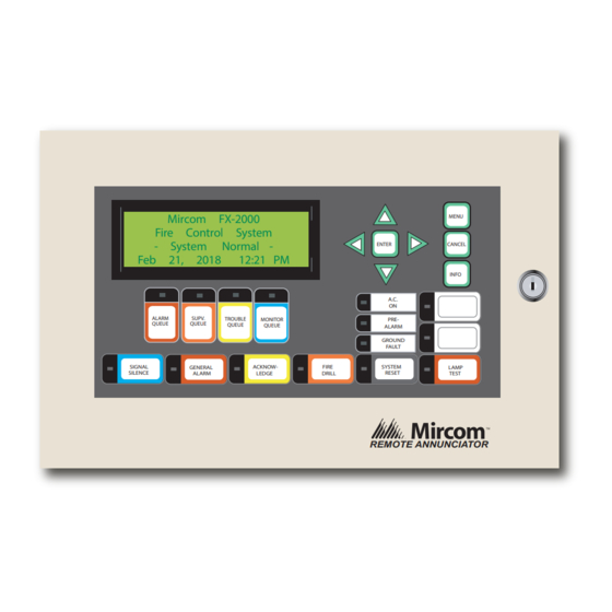
RAX-LCD
Remote FX-2000 Annunciator Panel
Jan 01, 2011
SIGNAL
SILENCE
Installation and Wiring Manual
Mircom FX-2000
Fire Control System
- System
Normal -
12:21 AM
ALARM
SUPV.
TROUBLE
MONITOR
QUEUE
QUEUE
QUEUE
QUEUE
GENERAL
ACKNOW-
LEDGE
ALARM
firealarmresources.com
MENU
ENTER
CANCEL
INFO
A.C.
ON
PRE-
ALARM
GROUND
FAULT
FIRE
SYSTEM
LAMP
DRILL
RESET
TEST
REMOTE ANNUNCIATOR
LT-856 Rev. 7.1
November 2011
Advertisement
Table of Contents

Related Manuals for Mircom RAX-LCD


Summary of Contents for Mircom RAX-LCD
- Page 1 RAX-LCD Remote FX-2000 Annunciator Panel Mircom FX-2000 MENU Fire Control System - System Normal - ENTER CANCEL Jan 01, 2011 12:21 AM INFO A.C. ALARM SUPV. TROUBLE MONITOR PRE- QUEUE QUEUE QUEUE QUEUE ALARM GROUND FAULT SIGNAL GENERAL ACKNOW- FIRE...
- Page 2 firealarmresources.com...
-
Page 3: Table Of Contents
The RAX-LCD Shared Display Chassis ................. Specifications and Features Enclosure Models ......................Module Models ....................... 5.2.1 RAX-LCD Remote FX-2000 Shared Display LCD Annunciator ........5.2.2 RAX-1048TZ Adder Annunciator Chassis (48 Display Points) ........Current Drain for Battery Calculations ................Environmental Specifications .................. - Page 4 Table of Contents 6.3.10 Insufficient Time ......................6.3.11 Component Failure ......................6.3.12 Inadequate Testing ......................6.3.13 Security and Insurance ....................Limited Warranty ......................6.4.1 International Warranty ....................6.4.2 Conditions to Void Warranty ..................Warranty Procedure ....................... Disclaimer of Warranties ....................Out of Warranty Repairs ....................
- Page 5 List of Figures and Tables List of Figures and Tables Table 1 Backboxes ........................Figure 1 Mechanical Assembly Diagram ..................Figure 2 Wiring Diagram ....................... Figure 3 Annunciator Panel Connections ..................Table 2 Maximum Wiring Run to Last Annunciator ..............Figure 4 Annunciator Connections ....................
- Page 6 List of Figures and Tables firealarmresources.com...
-
Page 7: Introduction
Introduction Introduction Mircom's FX-2000's remote shared display is the RAX-LCD. The RAX-LCD shared display provides an exact replica (less 16 zone LEDs) of the main FX-2000 Fire Alarm Panel display at a remote location. It is equipped with a large 4 line x 20 character back-lit alphanumeric LCD display that uses a simple menu system complete with a directional keypad and switches for Enter, Menu Cancel and Info. -
Page 8: Contact Us
For General Inquiries, Customer Service and Technical Support you can contact us Monday to Friday 8:00 A.M. to 5:00 P.M. E.S.T. 1.1.1 General Inquiries Toll Free 1-888-660-4655 (North America Only) Local 905-660-4655 Email mail@mircom.com 1.1.2 Customer Service Toll Free 1-888-MIRCOM5 (North America Only) Local 905-695-3535 Toll Free Fax 1-888-660-4113 (North America Only) -
Page 9: Installation Instructions
Installation Instructions Installation Instructions Table 1 Backboxes Backbox Height H (in.) Mounting A (in.) Mounting B (in.) BB-1001 9.0” 9.95” 7.5” BB-1002 18.0” 9.95” 16.5” BB-1003 26.5” 9.95” 24.9” BB-1008 33.0” 20.9” 35.2” BB-1012 45.0” 20.9” 52.0” WALL BACKBOX DOOR BACKBOX CAN BE MOUNTED WITH STANDARD 4"... -
Page 10: Wiring Instructions
No star wiring or T-tapping is 24 VDC POWER FROM FIRE ALARM CONTROL 24 VDC allowed. Each RAX-LCD PANEL OR PREVIOUS ANNUNCIATOR INPUT Shared Display has a 120 ohm end-of-line resistor on 24 VDC POWER TO its RS-485 output terminals. - Page 11 Wiring Instructions Note: All circuits are power limited and must use type FPL, FPLR, or FPLP power limited cable. Attention: Accidentally connecting any of the 24 VDC wires to the RS-485 wiring will result in damage to the annunciator and/or to the fire alarm control panel to which it is connected.
-
Page 12: Dip Switch Settings
SW1-8 during power up. At switches are ON. all other times put in “ON” state. The OFF setting is active. The addresses available for the RAX-LCD are 33 to 63. Set the address as follows in the table below: firealarmresources.com... -
Page 13: The Rax-1048 Adder Annunciator Chassis
ALARM SUPV. TROUBLE PRE- QUEUE QUEUE QUEUE QUEUE ALARM GROUND FAULT P2: Connects to the next RAX-1048TZ or SIGNAL ACKNOW- FIRE SYSTEM GENERAL LAMP SILENCE LEDGE DRILL RESET ALARM TEST IPS-2424. RAX-LCD SHARED DISPLAY BOARD Figure 4 Annunciator Connections firealarmresources.com... -
Page 14: The Rax-Lcd Shared Display Chassis
DIP Switch Settings The RAX-LCD Shared Display Chassis P1: Connects to the first RAX-1048TZ or IPS-2424. P2: BDM port. Terminals: See Wiring Instructions on page 10 for details. SW1: See above for details. Note: The last annunciator must have 120 ohm E.O.L. resistor connected to RS-485 output terminals. -
Page 15: Specifications And Features
Standby: 100 mA Max., All LED's "On": 150 mA Max. 5.2.2 RAX-1048TZ Adder Annunciator Chassis (48 Display Points) • Interconnect via one ribbon cable from RAX-LCD or to previous RAX-1048TZ or IPS- 2424 to the next RAX-1048TZ or IPS-2424. •... -
Page 16: Current Drain For Battery Calculations
Specifications and Features Current Drain for Battery Calculations The following are the currents for the RAX-LCD to which is added the number of RAX-1048TZ and/or IPS-2424 used: Normal Standby Current = 1000 mA+ ________ X 15 mA = ________ X 10mA =_______... -
Page 17: Warranty And Warning Information
Warranty and Warning Information Warranty and Warning Information Warning Please Read Carefully Note to End UsersThis equipment is subject to terms and conditions of sale as follows: Note to Installers This warning contains vital information. As the only individual in contact with system users, it is your responsibility to bring each item in this warning to the attention of the users of this system. -
Page 18: Compromise Of Radio Frequency (Wireless) Devices
Mircom shall not be liable for any delays, breakdowns, interruptions, loss, destruction, alteration or other problems in the use of a product arising our of, or caused by, the software. -
Page 19: Telephone Lines
During the warranty period, Mircom shall, at its option, repair or replace any defective product upon return of the product to its factory, at no charge for labor and materials. - Page 20 Mircom management, no credits will be issued for custom fabricated products or parts or for complete fire alarm system. Mircom will at its sole option, repair or replace parts under warranty. Advance replacements for such items must be purchased.
- Page 21 Products which Mircom determines to be repairable will be repaired and returned. A set fee which Mircom has predetermined and which may be revised from time to time, will be charged for each unit repaired.
- Page 22 firealarmresources.com...
- Page 23 firealarmresources.com...
- Page 24 CANADA - Main Office U.S.A TECHNICAL SUPPORT © Mircom 2011 25 Interchange Way 4575 Witmer Industrial Estates North America Printed in Canada Vaughan, ON L4K 5W3 Niagara Falls, NY 14305 Tel: (888) Mircom5 Subject to change without prior notice Tel: (888) 660-4655...
Need help?
Do you have a question about the RAX-LCD and is the answer not in the manual?
Questions and answers