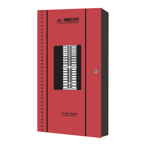
Mircom FA-300 Series User Manual
Led fire alarm control panel
Hide thumbs
Also See for FA-300 Series:
- Installation and operation manual (106 pages) ,
- User manual (20 pages) ,
- Installation and operation manual (20 pages)
Table of Contents
Advertisement
Quick Links
FA-300 Series
LED Fire Alarm Control Panel
Advanc ed Life Safety Solutio ns
User Guide
AC
LAMP
ON
TEST
REMOTE
COMMON
TROUBLE
ALARM
CPU
COMMON
FAULT
SUPERVISORY
GROUND
COMMON
FAULT
TROUBLE
BATTERY
TROUBLE
SIGNAL
SYSTEM
SILENECE
RESET
FIRE
AUXILIARY
DRILL
DISCONNECT
BUZZER
LAMP
SILENCE
TEST
MENU
INFO
ZONE DISCONNECT
ZONE DISCONNECT
Advanced Life Safety Solutions
Advan ced Life Safet y Solut ions
LAMP
AC
TEST
ON
REMOTE
COMMON
ALARM
TROUBLE
CPU
COMMON
SUPERVISORY
FAULT
GROUND
COMMON
TROUBLE
FAULT
BATTERY
TROUBLE
SIGNAL
SYSTEM
RESET
SILENECE
AUXILIARY
FIRE
DISCONNECT
DRILL
LAMP
BUZZER
TEST
SILENCE
MENU
INFO
ZONE DISCONNECT
ZONE DISCONNECT
LT-953 Rev. 0
June 2004
Advertisement
Table of Contents

Summary of Contents for Mircom FA-300 Series
- Page 1 Advanced Life Safety Solutions FA-300 Series LED Fire Alarm Control Panel Advanc ed Life Safety Solutio ns Advan ced Life Safet y Solut ions LAMP LAMP TEST TEST REMOTE COMMON REMOTE COMMON ALARM TROUBLE ALARM TROUBLE COMMON COMMON SUPERVISORY FAULT...
-
Page 3: Table Of Contents
FA-300 Series LED Fire Alarm Control Panel User Guide Contents Contents........................... i Introduction ..........................1 About this Manual ........................ 1 Technical Support ........................ 1 Main Display ..........................2 The Buzzer and LED Indicators ..................... 3 Common LED Indicators ...................... 3 Alarm Circuit Indicators ...................... -
Page 4: Contents
Contents... -
Page 5: Introduction
Refer to the Glossary on page 9 for an explanation of commonly used terms in this manual. Technical Support For all technical support inquiries, please contact Mircom’s Technical Support Department between 8 A.M. and 5 P.M. (EDT) Monday through Friday, excluding holidays. -
Page 6: Main Display
Paper labels for buttons and indicators Each display is supplied with laser printable labels. These labels slide into the plastic label templates on the panel. The label paper for the main display includes English and French versions (Mircom # NP-2005. -
Page 7: The Buzzer And Led Indicators
FA-300 Series LED Fire Alarm Control Panel User Guide The Buzzer and LED Indicators Common LED Indicators Buzzer The buzzer sounds if there is a fire alarm, a supervisory alarm, or a trouble in the fire alarm system. It turns off if the condition causing the buzzer to sound goes away or if the Buzzer Silence Button is pressed. - Page 8 The Buzzer and LED Indicators Walk Test LED The amber Walk Test indicator illuminates steadily to indicate that the panel is in walk test mode. If the panel is left in this mode for over an hour with no operator activity, the panel will return to normal WALK TEST and the Walk Test indicator will turn OFF.
-
Page 9: Alarm Circuit Indicators
FA-300 Series LED Fire Alarm Control Panel User Guide Alarm Circuit Indicators This operation applies to Initiating Circuits configured as Verified Alarm, Non-Verified Alarm, Water flow Alarm, Sprinkler Alarm, or General Alarm Circuits. The following table summarizes the indications at different events:... -
Page 10: Monitor Circuit Indicators
The Buzzer and LED Indicators Monitor Circuit Indicators This operation applies to initiating circuits configured as monitor circuits. The following table summarizes the indications in response to different events: Event Circuit Trouble LED Configuration Open circuit or (Style D)/(Class A) Flashes at the trouble rate trouble (amber) -
Page 11: Main Display Buttons
FA-300 Series LED Fire Alarm Control Panel User Guide Main Display Buttons System Reset Button The System Reset button resets the fire alarm control panel and all circuits. SIGNAL SILENCE Signal Silence Button Pressing the Signal Silence button when the panel is in alarm deactivates any silenceable signal SIGNAL devices in the fire alarm system. -
Page 12: Circuit (Zone) Disconnect Buttons
Circuit (Zone) Disconnect Buttons Circuit (Zone) Disconnect Buttons Circuit (zone) disconnect buttons are provided for all initiating and indicating circuits on the fire alarm control panel. These buttons are located beside their respective indicating LEDs. Pressing a circuit disconnect button disconnects that circuit from the system and turns on its trouble indicator. While a circuit is disconnected, the panel will ignore all changes in the status (alarms and troubles) of that circuit. -
Page 13: Glossary
FA-300 LED Fire Alarm Panel User Guide Glossary Alarm Occurs when devices such as detectors, pull stations, or sprinklers are activated. Condition In a single stage system, this condition will activate all signalling devices throughout the building. In a two stage system, this condition will activate an alert signal and the General Alarm timer. - Page 14 Glossary Supervisory Occurs when the sprinkler system is disconnected or turned off. Condition Trouble Occurs when an abnormal condition such as a problem in the wiring, battery or Condition power circuits exists in the fire alarm system. Trouble Flash 20 flashes per minute is the rate at which an LED will flash to indicate a trouble Rate condition.
- Page 16 Advanced Life Safety Solutions U.S.A. Canada Mircom 2004 Printed in Canada 60 Industrial Parkway 25 Interchange Way Subject to change without prior notice Cheektowaga, NY 14227 Vaughan, ON L4K 5W3 www.mircom.com Tel: 1-888-660-4655 Fax: 1-888-660-4113 Tel: 905-660-4655 Fax: 905-660-4113...


Need help?
Do you have a question about the FA-300 Series and is the answer not in the manual?
Questions and answers