
Related Manuals for Mircom FA-1025T


Summary of Contents for Mircom FA-1025T
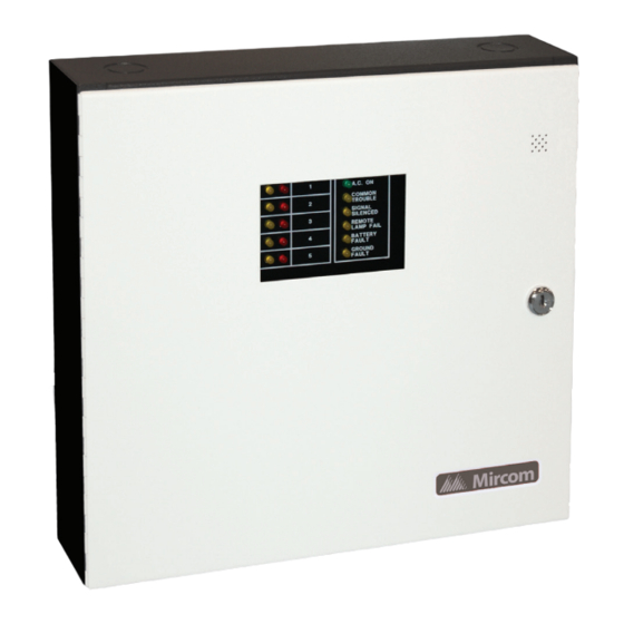
- Page 1 Advanced Life Safety Solutions FA-1025T Fire Alarm Control Panel A.C. ON SIGNAL SILENCED Installation and Operation Manual LT-493 Rev. 7 January 2006...
-
Page 3: Table Of Contents
FA-1025T Fire Alarm Control Panel Contents List of Figures.......................... ii Introduction ..........................1 Mechanical Installation ......................1 Function Selection ........................1 Wiring ............................2 Detection Zones ........................2 Signal Zone .......................... 2 Alarm and Trouble Relays....................2 Remote Annunciation......................3 A.C. -
Page 4: List Of Figures
List of Figures List of Figures Figure 1: Backbox and flush trim mounting details ..............5 Figure 2: Circuit Board Layout ....................6 Figure 3: Detection and signal wiring..................7 Figure 4: Wiring table for detection zone ................... 8 Figure 5: Wiring table for bells and horns .................. 8 Figure 6: Alarm and trouble relay contacts and remote annunciation wiring instructions .. -
Page 5: Introduction
FA-1025T Installation and Operation Manual Introduction The FA-1025T is a supervised five-zone 24VDC Fire Alarm Control Panel. The panel is ULC listed and meets all performance and operational requirements of ULC. The FA-1025T provides the following features: • Five Class B detection zones •... -
Page 6: Wiring
Wiring • JW7: Cut to enable supervision of remote annunciation alarm zone indicators. DIP switch DSW1 is used to set the preferred signal zone outputs, the signal silence inhibit, and the common trouble flash rate. not used DIP switch DSW1 Trouble Buzzer and LED Signal Zone 1 ON - steady buzzer and LED... -
Page 7: Remote Annunciation
FA-1025T Installation and Operation Manual Remote Annunciation Annunciation outputs are provided for alarm, remote trouble indicator and buzzer. Cut JW7 to enable lamp supervision for the remote annunciator alarm zones. Refer to Figure 6 on page 9 for wiring instruction. -
Page 8: Sequence Of Operation
Sequence of Operation Sequence of Operation Refer to Figure 2 on page 6 for the location of indicators and controls. Normal All indicators are normally OFF except for the green A.C. On LED. Alarm A red zone alarm LED will illuminate steadily for incoming alarm. Signal silence If the 60 second signal silence inhibit is selected, the signal cannot be silenced for 60 seconds after an alarm initiation. -
Page 11: Figure 3: Detection And Signal Wiring
FA-1025T Installation and Operation Manual Figure 3: Detection and signal wiring Legend Heat Smoke Pull Station Bell Detector Detector Alarm threshold current is 21 mA. Maximum loop resistance is 100 ohms. Detection zone 1 22VDC 3mA STBY 5mV ripple 3.9K 50 mA max. -
Page 12: Wiring Tables And Information
Wiring Tables and Information Wiring Tables and Information Figure 4: Wiring table for detection zone Wire Gauge Maximum Wiring Run to Last Device (ELR) (AWG) 2990 4760 1450 7560 2300 12000 3600 19000 5800 30400 9200 Note: Maximum loop resistance should not exceed 100 ohms. Figure 5: Wiring table for bells and horns Signal circuits are rated for 1.7 amperes each. -
Page 13: Figure 6: Alarm And Trouble Relay Contacts And Remote Annunciation Wiring Instructions
FA-1025T Installation and Operation Manual Figure 6: Alarm and trouble relay contacts and remote annunciation wiring instructions N.O. Auxiliary common alarm relay contacts 28VDC, 3A (resistive) N.C. Common trouble Cut JW3 for N.O. relay contacts 28VDC, 3A Cut JW4 for N.C. -
Page 14: Appendix A: Compatible Devices
• Whether mixing different models of compatible smoke detectors, or using the same model on the same Circuit, total standby current of all detectors must not exceed 3 Make Model / Base Make Model / Base Make Model / Base Mircom Cerebrus Pyrotronics Fenwal MIR-525 D1-2... -
Page 15: Underwriter's Labs Inc. (Uli) United States 2-Wire Smoke Detector Control Panel Compatibility
FA-1025T Installation and Operation Manual Underwriter’s Labs Inc. (ULI) United States 2-Wire Smoke Detector Control Panel Compatibility Notes: • Reset time, hold for five seconds minimum. • Whether mixing different models of compatible smoke detectors, or using the same model on the same circuit, total standby current of all detectors must not exceed 3 •... - Page 16 A - A 0.12 mA B401 4451HT / A - A 0.12 mA B401B 4451HT / A - A 0.12 mA Mircom B406B 4451HT / A - A 0.12 mA MIR-525U FDT-1 0.10 mA B401 5451 / A - A 0.12 mA...
-
Page 17: Underwriter's Labs Inc. (Uli) United States Signaling Device Control Panel Compatibility
FA-1025T Installation and Operation Manual Underwriter’s Labs Inc. (ULI) United States Signaling Device Control Panel Compatibility System Sensor - SpectrAlert P2415 P2415W P241575 P241575W P2475 P2475W P24110 P24110W S2415 S2415W S241575 S241575W S2475 S2475W S24110 S24110W H12/24 H12/24W MDLW Wheelock... -
Page 18: Appendix B: Battery Calculations (Selection Guide)
Power Requirements (All currents are in amperes) Model Total Total Description Standby Alarm Number Standby Alarm Fire Alarm, 5 Det, FA-1025T 0.114 0.200 2 Sig Annunciator, 5 RA-105 0.016 0.032 Circuits Remote Trouble RTI-1 0.035 0.035... -
Page 19: Warranty
Mircom Technologies Ltd., manufactured equipment is guaranteed to be free of defects in material and workmanship for a period of one (1) year from the date of original shipment. Mircom will repair or replace, at its option, any equipment which it determines to contain defective material or workmanship. - Page 20 Advanced Life Safety Solutions U.S.A. Canada Mircom 2006 Printed in Canada 25 Interchange Way 4220 Steve Reynolds Blvd, Unit 17 Subject to change without prior notice Vaughan, ON L4K 5W3 Norcross (Atlanta), GA 30093 www.mircom.com Tel: 905-660-4655 Fax: 905-660-4113...
Need help?
Do you have a question about the FA-1025T and is the answer not in the manual?
Questions and answers