Table of Contents
Advertisement
Quick Links
Advertisement
Table of Contents

Related Manuals for Denso BHT-200


Summary of Contents for Denso BHT-200
- Page 1 Supported Equipment Manual for the BHT-200 device manufactured by Denso...
- Page 2 Copyright © 1996 - 2006 by Connect, Inc. All rights reserved. This document may not be reproduced in full or in part, in any form, without prior written permission of Connect, Inc. 1701 Quincy Avenue, Suites 5 & 6, Naperville, IL 60540.
-
Page 3: Table Of Contents
Running the Manager……...................2-4 Quick Start………………… ...................2-5 Configuring the Manager ..................2-5 Booting the Terminal ..................2-11 Configuring the BHT-200 Terminal for Download..........2-12 Starting a Telnet Session .................2-13 Standard Setup……………..................2-13 Setup Using Twin Client Manager ..............2-13 Terminal Setup Using Twin Client Menus ............2-19 Authorizing PowerNet..................2-20... - Page 4 ____________________________________________________________________________________ This page is intentionally blank. • PowerNet Twin Client Reference May, 2006...
-
Page 5: Chapter 1 • Introduction
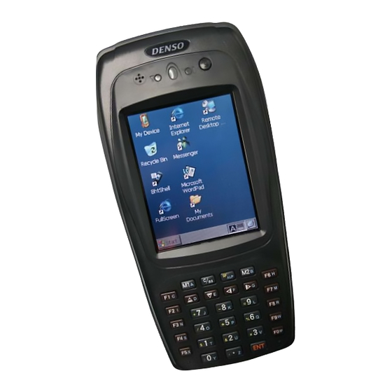
All versions of firmware will work on the BHT200 terminal. Description The Denso BHT-200 is 203x75x50mm in size and weighs approximately 14 oz. It features an Intel XScale PXA250 CPU with memory of 32 MB RAM and 32 MB RAM. -
Page 6: Setup Requirements
Microsoft Windows CE.NET operating system • ActiveSync needs to be installed on the PC before downloading files to the terminal. For instructions, go to http://www.MSDN.Microsoft.com Accessories The following accessories are available for the BHT-200: • Hand Strap • Stylus •... -
Page 7: Chapter 2 • Terminal Setup
. Click on Partner Services and then click on Software http://www.connectrf.com Downloads. Select the file named PowerNet Twin Client for Denso. Running Setup from a Download File The downloaded file is a compressed archive. After extraction using a utility such as WinZip or PKWARE, folders are created on the hard disk as shown in the following figure. -
Page 8: Installation
Terminal Setup Installation The InstallShield wizard runs and presents the following screen. Click on to begin the installation process. Next To change the default Destination Location, click on and select a location. Then Browse click on Next • Supported Equipment Manual May, 2006... - Page 9 Installation The default folder is . This default may be changed either by selecting an PowerNet existing program group or by typing in a new name at the prompt. Then click on Next. When the installation is complete, reboot the system to initialize the Twin Client software.
-
Page 10: Running The Manager
Terminal Setup b. To reboot later, click on the option to restart the computer later, and then click on Finish Running the Manager The PowerNet Twin Client Manager is the utility that manages the terminal software and configurations. Select , and . -
Page 11: Quick Start
Quick Start Quick Start This section describes how to prepare the Twin Client Manager and the Denso terminal for a Telnet session with the host. Following an initial serial download, the terminal software and configuration are managed automatically over the wireless network. - Page 12 Terminal Setup To set these addresses from the menu, click on Settings Servers. Then click on . Enter the name of the server, its IP address and IP port (normally 23 for Telnet servers), and terminal type. Then click on Repeat this step for each Telnet server the terminals are required to access.
- Page 13 Denso terminal model, or to change the port assignment, click on the menu as shown. Options To maintain compatibility with existing Denso Telnet client keyboard layouts, a specific terminal model must be selected from the Terminal Model window. • Supported Equipment Manual...
- Page 14 Terminal Setup Select when finished Saving the Configuration Click . Enter a name for this configuration. File Save As For the purposes of this example, the name is vt100 • Supported Equipment Manual May, 2006...
- Page 15 Quick Start Setting Airloader Auto-Configuration The configuration download and IP address assignment for each terminal will take place automatically by setting the Airloader Auto-Configuration options. Click on the option in the menu. Airloader Tools If the Airloader Auto-Configuration window does not display the options, click on Note: button.
- Page 16 Terminal Setup After setting the address range, click on to return to the Airloader Auto-Configuration screen and then click on the box next to Terminal/Group Manager The display expands to show the default terminal group. Next, click on the New Group icon and use the button to select the configuration file saved earlier.
-
Page 17: Booting The Terminal
Quick Start Check the box, and the system is now configured to automatically download IP Active addresses, software, and configuration files to the terminals. Click on the box in the upper right corner to return to the main menu. The software does not need to be authorized now. It can be authorized later, after a Note: Telnet session has been established. -
Page 18: Configuring The Bht-200 Terminal For Download
The terminal download requires a serial connection between the terminal and the PC through a cable. In preparation for this download, connect the cable to the selected serial port on the PC and to the BHT-200 terminal. On the PC, click on , and . -
Page 19: Starting A Telnet Session
Standard Setup Starting a Telnet Session At the Twin Client main menu on the terminal, press any key to establish the connection. Until the terminal has been authorized, the following screen is displayed. RECOVERABLE ERROR Terminal not Authorized for Twin Client Keypress to continue…... - Page 20 Terminal Setup Then click on the selection, as shown below. VT100 VT220 Click on after the selection is made, and return to the main Twin Client Manager menu. The standard settings tab will now reflect the settings for VT emulation. Quadrant Mode This scrolling list option defines the rules by which the terminal display is positioned in the larger host display.
- Page 21 Standard Setup enables quadrant processing. However, input fields that cross quadrant boundaries result in a shift to the left in order to locate as much of the current input field on the terminal display. always positions on a quadrant boundary regardless of input field boundaries. Soft Viewing keys are enabled.
- Page 22 Terminal Setup Click on after the selection is made, and return to the main Twin Client Manager menu. The standard settings tab will now reflect the settings for 5250 emulation. Quadrant Mode This scrolling list option defines the rules by which the terminal display is positioned in the larger host display.
- Page 23 Standard Setup always positions on a quadrant boundary regardless of input field boundaries. Soft Viewing keys are enabled. is the same as except the viewing keys are disabled. Hard Soft locks the terminal display origin (upper left corner) to fixed row and column Lock (x,y) coordinates in the host display.
- Page 24 Terminal Setup Click on after the selection is made, and return to the main Twin Client Manager menu. The standard settings tab will now reflect the settings for 3270 emulation. Quadrant Mode This scrolling list option defines the rules by which the terminal display is positioned in the larger host display.
-
Page 25: Terminal Setup Using Twin Client Menus
Standard Setup Key Click This check box enables (checked) or disables (unchecked) audible key clicks from the terminal. The default value is (checked). Printer Type This scrolling list selects the attached printer type. The default value is indicating none, that no printer is attached. Terminal Setup Using Twin Client Menus The Twin Client terminal software provides an internal menu system for configuring certain parameters on the terminal and for switching between Server and Telnet modes of... -
Page 26: Authorizing Powernet
Terminal Setup Host 0 IP 206.183.67.155 Port 23__ <F3> Save <F7> Quit Press to save the configurations. Edit License Key The client software can be authorized automatically, as described in the next section, Authorizing PowerNet. This menu option permits authorization of each terminal manually. - Page 27 Standard Setup The Twin Client Manager can automatically authorize the terminal over the wireless network if the following requirements are met: • A PC running Twin Client Manager is connected to the wire LAN segment with at least one access point within range of the terminal. •...
- Page 28 Terminal Setup Go to Click on . Click on the http://www.connectrf.com. Partner Services Generate icon at the top of the page. Follow the directions on the web site. Authorization Authorized Terminals The number of terminals authorized, the number of terminals in use, and the number of terminals remaining is provided in the Authorized Terminals box on the lower left side of the screen.
- Page 29 Standard Setup From Twin Client Manager, choose from under the menu. Authorization Tools Click on the button. Add Licenses A pop-up box appears with the Machine ID and a space for the additional license’s Authorization code. Enter the additional license’s Authorization code and click on Use the Machine ID in the pop-up box instead of the original Machine ID to get your Authorization code.
- Page 30 Terminal Setup Transfer Authorization The Transfer Authorization feature is used when moving a site license from one PC to another. After Twin Client Manager is installed on a new PC, you will need the System/Machine ID for it. This ID appears in the first box of the Authorization screen. From Twin Client Manager, select from under the menu.
-
Page 31: Software Management
Software Management Click on when finished. Click on the button when finished. Close Software Management In addition to providing functions for the download of files to the terminal via the traditional serial connection, the Twin Client Manager also provides for the management of terminal software and configurations automatically over the wireless network. - Page 32 Terminal Setup If no options are displayed, click on the button. Note: Advanced<< Enabling Automatic Downloads Click to put a check in the box that allows terminals to be automatically configured via RF to enable automatic downloading. In the event that another PC on the network is already configured and active, the following warning message is displayed.
- Page 33 Software Management Automatic IP Address Assignment An IP address does not need to be assigned to the terminal. The terminal can find the airloader server automatically. Creating New Groups New groups, with different configurations, can be created by clicking on , and then clicking the right mouse button as shown.
- Page 34 Terminal Setup Clicking on the button will cause all terminals in this group that are currently Thin Mode running in thick mode to be switched to thin mode the next time Airloader is run on the terminal. Click on the button to view a dialog box for scheduling an automatic Airloader Schedule update.
- Page 35 Software Management Setting the Segment Checking the button restricts a terminal group to a range of IP addresses. The Segment IP Address can be any valid address on the segment as it is used only to identify the segment. The setting of the Net Mask can be used to restrict the range. This feature is useful for segregating terminal groups by location.
-
Page 36: Mobile Device Manager (Mdm) Features
Terminal Setup Then, holding the mouse button down, drag the terminal icon to the desired group as shown next. Release the mouse button, which reassigns the terminal. The next time the terminal is rebooted, it will be reconfigured as defined in the group specification. - Page 37 Software Management A screen will appear with a display resembling the terminal screen. Clicking on the button on the upper left brings up a screen in which you can modify Font the font settings, as shown below. • 2-31 Supported Equipment Manual May, 2006...
- Page 38 Terminal Setup Select from the menu. Terminal Messenger Tools You may enter an Address Range in the boxes on this screen. Click on From when finished. Enter a message to send in the space provided, select the terminal to receive this message by clicking on it in the column, and click on the button to send...
- Page 39 Software Management Select from the menu. RF Monitor Tools RF Monitor is an "Over The Air" diagnostic tool. It's used to collect diagnostic trace information from RF terminals running PowerNet Twin Client software. It runs on a Windows PC and will send a command to the RF terminal to start tracing. The terminal, when it receives this command, will start sending the trace information over the RF link to the PC that issued the command.
- Page 40 Terminal Setup Click on Select Find, and/or Find Next to search for pieces of information in your Edit. log, or select Clear to clear the search. Click on to select Start Monitor or Stop Monitor. Actions Click on to choose Set Debug Levels or Settings. Tools The options in Debug Levels are shown below.
- Page 41 Software Management The maximum log file size can be set under Settings. Click on to show or hide the Toolbar and the Status Bar. View This is the Toolbar. It is found near the top of the screen. This is the Status Bar. It is found at the bottom of the screen. Click on under to view version number information.
- Page 42 Terminal Setup RF Monitor is a very small program and does not even require installation. Just place it in a directory on your PC and create a shortcut to run it. It will run on all versions of Windows except V3.1 and Windows 95. 1.
- Page 43 Software Management With the RF terminal sitting at the prompt, select Press Any Key Actions/Start Monitor. 7. Press a key on the RF terminal to open a session, and you should see trace data in the RF Monitor window. When done, end the trace and the file will be named (where is the last 2 octets of the RF terminal’s IP address) in tnxxx.yyy.log...
- Page 44 Terminal Setup Common Problems with RF Monitor • The trace won’t start. RF Monitor uses UDP to send commands to the RF device. On busy networks UDP packets are not always delivered. The terminal can miss the command to start the trace.
- Page 45 Software Management a. Emulation protocols (IBM 5250, IBM 3270, DEC VT200, etc.) b. PowerNet Twin Client products c. RF network concepts d. Wired network concepts e. Telnet sessions f. TCP/IP They are text files that can be read with any editor or viewer and can be useful to end users and integrators even if they may not have all the requirements above.
-
Page 46: Sending Program And Configuration Files To The Terminal
Terminal Setup Sending Program and Configuration Files to the Terminal Boot the terminal. 2. On the PC, select from the menu in Twin Send Program Files to Terminal Terminal Client Manager. The following screen will appear. 3. Click on The following screen will appear. 4. - Page 47 Software Management 6. Choose 7. Click on The following screen will appear. 8. Click on 9. Warm boot the terminal. Under , you may select Terminal Receive File from Terminal Enter the path and file name to receive from the terminal in the Upload File dialog box. •...
- Page 48 Terminal Setup The default file is “ ”. Click on rf.log • 2-42 Supported Equipment Manual May, 2006...
-
Page 49: Chapter 3 • Keypad Configuration
Chapter 3 • Keypad Configuration C BS SF ALP pg▲ bktab A Diagrams ▲ ▼ ◄ ► vw▲ vw▼ E vw◄ F vw► pg▼ eeof erase find select remove & home insert VT emulation Note: F10 does space in alpha mode. keytop •... - Page 50 Keypad Configuration C BS SF ALP bktab ▲ ▼ ◄ ► vw▲ vw▼ E vw◄ F vw► sreq clear reset eeof erase & home insert 3270 emulation Note: F10 does space in alpha mode. keytop • May, 2006 Supported Equipment Manual...
- Page 51 Table C BS SF ALP bktab rl▲ ▲ ▼ ◄ ► vw▲ vw▼ E vw◄ F vw► rl▼ sreq clear reset eeof print newl attn erase & fld- fld+ fld ex home insert 5250 emulation Note: F10 does space in alpha mode. keytop •...
-
Page 52: Table
Keypad Configuration Table 3270 5250 <Alp><M1> <Alp><M1> <Alp><M1> <Alp><M2> <Alp><M2> <Alp><M2> <Alp><F1> <Alp><F1> <Alp><F1> <Alp><▲> <Alp><▲> <Alp><▲> <Alp><▼> <Alp><▼> <Alp><▼> <Alp><◄> <Alp><◄> <Alp><◄> <Alp><►> <Alp><►> <Alp><►> <Alp><F6> <Alp><F6> <Alp><F6> <Alp><F2> <Alp><F2> <Alp><F2> <Alp><7> <Alp><7> <Alp><7> <Alp><8> <Alp><8> <Alp><8> <Alp><9> <Alp><9> <Alp><9>... - Page 53 Table View left <SF><◄> <SF><◄> <SF><◄> View right <SF><►> <SF><►> <SF><►> <1> <1> <1> <2> <2> <2> <3> <3> <3> <4> <4> <4> <5> <5> <5> <6> <6> <6> <7> <7> <7> <8> <8> <8> <9> <9> <9> <0> <0> <0>...
- Page 54 Keypad Configuration Remove <M2><3> Reset <M2><9> <M2><9> Roll up <M2><F6> Roll down <M2><F7> Select <M2><2> <M2><7> <M2><7> Sysreq Note: F10 does space in alpha mode. • May, 2006 Supported Equipment Manual...
-
Page 55: Chapter 4 • Error Message Resolution Guide
Chapter 4 • Error Message Resolution Guide Twin Client Error Message Resolution Guide Message Reason Solution Reference Tech Note ENTRY TOO LONG; Trying to key beyond the field size. Ensure that you are entering input into the correct field. ALPHABETIC ONLY; Trying to key a character that is not Ensure that you are entering input into the alphabetic. - Page 56 Error Message Resolution Guide Message Reason Solution Reference Tech Note INVALID KEY; The key pressed is not valid. Ensure that you are entering input into the correct field. MUST CLEAR FIELD; Trying to enter data in a field that must be Ensure that you are entering input into the cleared first.
- Page 57 Error Message Resolution Guide Message Reason Solution Reference Tech Note Disconnect Could Not Disconnect. Verify that your Network settings are correct T1113, T1114, T1161, ERROR.\nREBOOT and you are in the correct mode using the T1171, T1187 and MOBILE UNIT; correct Port. T1194 RF Send Could not send.
- Page 58 Error Message Resolution Guide Message Reason Solution Reference Tech Note TIMEOUT\n\nReceiving Mobile Unit out of the coverage area. Most likely a range, access point, radio, T1113, T1114, T1161, Data; host or network issue. Troubleshoot the T1171, T1187 and customer’s environment. T1194 Host Received Mobile Unit has sent and received an...
- Page 59 Error Message Resolution Guide Message Reason Solution Reference Tech Note Error receiving host\nlist Bad Protocol detected. Usually a result of bad cabling, power or from Server; faulty transceiver. Also, will receive this if the Mobile Unit is in the wrong mode for Server operation.
- Page 60 Error Message Resolution Guide Message Reason Solution Reference Tech Note User Count Exceeded.\n Possible authorization issue. Verify that you have the correct number of Session Ended; licenses for the number of Mobile Units you are using. Primary Unavailable\nTrying First Host IP address not available trying the Verify that the host address.
- Page 61 Error Message Resolution Guide Message Reason Solution Reference Tech Note Printer Not Ready\nPress R Can not print. Check cable, battery, communication to Retry\nC to Cancel Print; settings and paper in the printer. Mobile Unit Running in demo mode. Purchase a license from Connect. in\nDemonstration Mode\nfor TwinClient;...
- Page 62 Error Message Resolution Guide Message Reason Solution Reference Tech Note TwinClient Server; Prompt. Advisory message. TwinClient TN3270; Prompt. Advisory message. TwinClient TN5250; Prompt. Advisory message. TwinClient TNVT; Prompt. Advisory message. (c)1991-2006 Connect; Prompt. Advisory message. Edit Menu Options; Menu Title. Advisory message.
- Page 63 Error Message Resolution Guide Message Reason Solution Reference Tech Note Switch Client Modes; Menu Option. Advisory message. Run TwinClient; Menu Option. Advisory message. Exit to OS; Menu Option. Advisory message. Printer may not be\nplugged Can not print. Check cable, battery, communication in or\nturned on!;...
- Page 64 Error Message Resolution Guide Message Reason Solution Reference Tech Note Printer Out\nOf Range; Printer out of the coverage area. Most likely a range, access point or radio T1113, T1114, T1161, issue. Troubleshoot the customer’s T1171, T1187 and environment. T1194 Connection Refused\nBy You connected to the target host but the host Verify that the configuration file has the Host;...
- Page 65 Error Message Resolution Guide Message Reason Solution Reference Tech Note Print Complete; Prompt. Advisory message. Reprint (Y/N)?; Yes or No prompt for a reprint. Advisory message. WARNING; Prompt. Advisory message. Turning power off\nduring a This Mobile Unit will disconnect the session if Mobile Unit manufacturer limitation.
- Page 66 Error Message Resolution Guide Message Reason Solution Reference Tech Note Domain Name Mobile Unit out of the coverage area. Most likely a range, access point, radio, T1113, T1114, T1161, Server\nQuery Receive host or network issue. Troubleshoot the T1171, T1187 and Error;...
- Page 67 Error Message Resolution Guide Message Reason Solution Reference Tech Note Disconnecting...; Prompt. Advisory message. Scan Barcode; Bar code scanning test. Advisory message. Enter Setup\nPassword; Prompt. Advisory message. Enter Profile \nPassword; Prompt. Advisory message. Host IP; Host IP address prompt. Enter target host IP address. Host Name;...
- Page 68 Error Message Resolution Guide Message Reason Solution Reference Tech Note HOST ENTRY; Prompt. Advisory message. VT(100/220) Setup; Prompt. Advisory message. Mobile Unit Info; Prompt. Advisory message. Emulation Setup; Prompt. Advisory message. ANSI Setup; Prompt. Advisory message. Miscellaneous Setup; Prompt. Advisory message. Mobile Unit Type;...
- Page 69 Error Message Resolution Guide Message Reason Solution Reference Tech Note Insert Mode; Prompt. Advisory message. Autowrap Mode; Prompt. Advisory message. Cursor; Prompt. Advisory message. EMULATION SETUP; Prompt. Advisory message. Mobile Unit Type; Prompt. Advisory message. Local Echo; Prompt. Advisory message. Map Underline;...
- Page 70 Error Message Resolution Guide Message Reason Solution Reference Tech Note MISCELLANEOUS SETUP; Prompt. Advisory message. Test Options; Prompt. Advisory message. Login Options; Prompt. Advisory message. TEST OPTIONS; Prompt. Advisory message. Printer Test; Prompt. Advisory message. Scan Code Test; Prompt. Advisory message. LOGIN OPTIONS;...
- Page 71 Error Message Resolution Guide Message Reason Solution Reference Tech Note Map; Prompt. Advisory message. Don't Map; Prompt. Advisory message. Enable Break; Prompt. Advisory message. Disable Break; Prompt. Advisory message. 7 bit; Prompt. Advisory message. 8 bit; Prompt. Advisory message. Send Delete; Prompt.
- Page 72 Error Message Resolution Guide Message Reason Solution Reference Tech Note Special Options; Prompt. Advisory message. Beeper Options; Prompt. Advisory message. Exit to DOS; Prompt. Advisory message. Backlight Time; Prompt. Advisory message. Enter Key Action; Prompt. Advisory message. Reset Options; Prompt. Advisory message.
- Page 73 Error Message Resolution Guide Message Reason Solution Reference Tech Note Modify Beeps; Prompt. Advisory message. Message Beeps; Prompt. Advisory message. Scan Identifier; Prompt. Advisory message. AID Scan Setup; Prompt. Advisory message. Long Scans; Prompt. Advisory message. Scan Send; Prompt. Advisory message. Yes;...
- Page 74 Error Message Resolution Guide Message Reason Solution Reference Tech Note Double High and Wide; Prompt. Advisory message. Errors Only; Prompt. Advisory message. Automatic; Prompt. Advisory message. All Messages; Prompt. Advisory message. Reject; Prompt. Advisory message. Truncate; Prompt. Advisory message. Split; Prompt.
- Page 75 Error Message Resolution Guide Message Reason Solution Reference Tech Note External; Prompt. Advisory message. none; Prompt. Advisory message. monarch; Prompt. Advisory message. pddumb; Prompt. Advisory message. comtec; Prompt. Advisory message. rascal; Prompt. Advisory message. codewriter; Prompt. Advisory message. comtec(S); Prompt. Advisory message.
- Page 76 Error Message Resolution Guide Message Reason Solution Reference Tech Note Duration: Prompt. Advisory message. Delay: Prompt. Advisory message. Select Scanner; Prompt. Advisory message. Setup Scanner; Prompt. Advisory message. Scan Test; Prompt. Advisory message. Scan Operation; Prompt. Advisory message. Laser; Prompt. Advisory message.
- Page 77 Error Message Resolution Guide Message Reason Solution Reference Tech Note Wand Simulation; Prompt. Advisory message. VT100; Prompt. Advisory message. VT220; Prompt. Advisory message. SETUP; Prompt. Advisory message. Mobile Unit IP/Radio; Prompt. Advisory message. Host List; Prompt. Advisory message. NULL; Prompt. Advisory message.
Need help?
Do you have a question about the BHT-200 and is the answer not in the manual?
Questions and answers