Siemens SIMATIC RF610R System Manual
Hide thumbs
Also See for SIMATIC RF610R:
- Getting started (27 pages) ,
- Configuration manual (144 pages)
Table of Contents
Advertisement
Quick Links
S S IMATIC RF600
SIMATIC Ident
RFID systems
S
S
IMATIC RF600
System Manual
06/2019
J31069-D0171-U001-A22-7618
Introduction
Safety Information
System overview of
S S IMATIC RF600
RF600 system planning
Readers
Antennas
Transponder
Integration into networks
System diagnostics
Accessories
Appendix
1
2
3
4
5
6
7
8
9
10
A
Advertisement
Table of Contents

Related Manuals for Siemens SIMATIC RF610R


Summary of Contents for Siemens SIMATIC RF610R
- Page 1 S S IMATIC RF600 Introduction Safety Information System overview of S S IMATIC RF600 SIMATIC Ident RF600 system planning RFID systems IMATIC RF600 Readers Antennas System Manual Transponder Integration into networks System diagnostics Accessories Appendix 06/2019 J31069-D0171-U001-A22-7618...
- Page 2 Note the following: WARNING Siemens products may only be used for the applications described in the catalog and in the relevant technical documentation. If products and components from other manufacturers are used, these must be recommended or approved by Siemens. Proper transport, storage, installation, assembly, commissioning, operation and maintenance are required to ensure that the products operate safely and without any problems.
-
Page 3: Table Of Contents
T T able of contents Introduction............................13 Preface............................13 Abbreviations and naming conventions ..................14 Safety Information..........................15 General safety instructions .....................15 Safety instructions for third-party antennas as well as for modifications to the RF600 system.............................19 Safety distance to transmitter antenna ...................20 2.3.1 Safety distance between transmitter antenna and personnel ..........20 2.3.2... - Page 4 Table of contents 4.3.9.4 Types of antenna ........................53 4.3.9.5 Antenna cables ........................53 Minimum distances and maximum ranges ................55 4.4.1 Configurations of antenna and transponder ................55 4.4.2 Effects of the materials of the mounting surfaces on the range ..........58 4.4.3 Maximum read/write ranges of transponders ................
- Page 5 Table of contents Readers .............................. 105 Overview ..........................105 SIMATIC RF610R .........................107 5.2.1 Description ..........................107 5.2.1.1 Overview ..........................107 5.2.1.2 Ordering data ........................108 5.2.1.3 Pin assignment of the power supply interface (X80 24VDC)..........109 5.2.1.4 Pin assignment of the Industrial Ethernet interface (X1 P1)..........110 5.2.1.5...
- Page 6 Table of contents 5.4.1.5 Pin assignment of the power supply interface (X80 24VDC)..........153 5.4.1.6 Pin assignment of the Industrial Ethernet interface (X1 P1) ..........155 5.4.1.7 Grounding connection ......................155 5.4.2 Planning operation ....................... 156 5.4.2.1 Antenna/read point configurations ..................156 5.4.3 Installation/mounting ......................
- Page 7 Table of contents SIMATIC RF650M.........................229 5.7.1 Description ..........................229 5.7.2 Field of application and features...................229 Antennas ............................231 Overview ..........................231 SIMATIC RF615A .........................233 6.2.1 Characteristics ........................233 6.2.2 Ordering data ........................234 6.2.3 Mounting ..........................234 6.2.4 Connecting the antenna......................235 6.2.5 Antenna parameter assignment....................236 6.2.6 Antenna patterns........................238 6.2.6.1...
- Page 8 Table of contents SIMATIC RF642A ........................ 293 6.5.1 Characteristics ........................293 6.5.2 Ordering data ........................294 6.5.3 Installation ..........................294 6.5.4 Connecting the antenna....................... 295 6.5.4.1 Bending radii and bending cycles of the cable ..............296 6.5.5 Antenna parameter assignment................... 297 6.5.5.1 Alignment of transponders to the antenna................
- Page 9 Table of contents 6.8.6.3 Interpretation of directional radiation patterns ..............354 6.8.7 Technical data........................355 6.8.8 Dimension drawing .......................357 6.8.9 Approvals & certificates ......................358 Transponder ............................359 Overview ..........................359 7.1.1 Mode of operation of transponders..................359 7.1.2 Transponder classes and generations..................360 7.1.3 Electronic Product Code (EPC) ....................360 7.1.4 SIMATIC memory configuration of the RF600 transponders and labels ......362 7.1.5...
- Page 10 Table of contents 7.7.3.1 Range when mounted on flat metallic carrier plates............400 7.7.3.2 Range when mounted on non-metallic carrier materials ............. 401 7.7.4 Technical specifications ....................... 402 7.7.5 Dimension drawing ......................404 7.7.6 Certificates and approvals ....................405 SIMATIC RF625T......................... 406 7.8.1 Characteristics ........................
- Page 11 Table of contents 7.12.3 Planning the use ........................442 7.12.3.1 Optimum antenna/transponder positioning with plane mounting of the transponder on metal .............................442 7.12.3.2 Range when mounted on flat metallic carrier plates.............443 7.12.3.3 Range when mounted on non-metallic carrier materials ............443 7.12.3.4 Use of the transponder in the hazardous area ..............444 7.12.3.5 Use of the transponder in the hazardous area for gases .............444...
- Page 12 Table of contents 10.2.5 Dimension drawing ......................496 10.3 Reader and antenna holders ....................497 10.3.1 Overview ..........................497 10.3.2 Ordering data ........................497 10.3.3 Mounting with the SIMATIC antenna holder ................ 497 10.3.4 Dimension drawing ......................499 Appendix .............................503 Certificates &...
-
Page 13: Introduction
Do not dispose of the products at public disposal sites. For environmentally compliant recycling and disposal of your electronic waste, please contact a company certified for the disposal of electronic waste or your Siemens representative. Note the different country-specific regulations. -
Page 14: Abbreviations And Naming Conventions
Expansion of the documentation by the following: Reader SIMATIC RF615R 06/2019 Expansion of the documentation by the following: Reader SIMATIC RF610R Transponder RF630L Declaration of conformity The EC declaration of conformity and the corresponding documentation are made available to authorities in accordance with EC directives. Your sales representative can provide these on request. -
Page 15: Safety Information
S S afety Information 2 2 .1 General safety instructions Note H H eed the safety notices Please observe the safety instructions on the back cover of this documentation. SIMATIC RFID products comply with the salient safety specifications to VDE/DIN, IEC, EN, UL and CSA. - Page 16 Safety Information 2.1 General safety instructions O O perating temperature CAUTION Increased temperatures on the lower casing Note that the lower casing of the readers is made of metal. This means that temperatures can occur on the lower casing that are higher than the maximum permitted operating temperature.
- Page 17 Safety Information 2.1 General safety instructions L L ightning protection CAUTION Installation only in protected areas Antennas and readers can be installed in the protected part of a building. When implementing your lightning protection concept, make sure you adhere to the VDE 0182 or IEC 62305 standards.
- Page 18 Siemens’ products and solutions undergo continuous development to make them more secure. Siemens strongly recommends that product updates are applied as soon as they are available and that the latest product versions are used. Use of product versions that are no longer supported, and failure to apply the latest updates may increase customers’...
-
Page 19: Safety Instructions For Third-Party Antennas As Well As For Modifications To The Rf600 System
Safety Information 2.2 Safety instructions for third-party antennas as well as for modifications to the RF600 system 2 2 .2 Safety instructions for third-party antennas as well as for modifications to the RF600 system Always observe the following general safety instructions before selecting a component from a different vendor: The manufacturer accepts no responsibility for functional suitability or legal implications for the installation of third-party components. -
Page 20: Safety Distance To Transmitter Antenna
Safety Information 2.3 Safety distance to transmitter antenna N N ote U U ser responsibility for modified product As a user of the modified product, you accept responsibility for use of the complete RFID product comprising both SIMATIC RF600 components and third-party RFID components. This particularly applies to modification or replacement of: Antennas Antenna cables... -
Page 21: Minimum Distance To Antenna In Accordance With Etsi
Safety Information 2.3 Safety distance to transmitter antenna 2 2 .3.2 Minimum distance to antenna in accordance with ETSI At a transmission frequency of 900 MHz, the wavelength of the electromagnetic wave approximately 0.34 m. For distances less than 1 in the near field, the electrical field strength (1/r) diminishes exponentially to the power three over distance, and for distances greater than 1 , it diminishes exponentially to the power two over distance. -
Page 22: Minimum Distance To Antenna In Accordance With Fcc
N N ote R R educed maximum radiated power with RF600 readers SIMATIC RF610R and RF615R (ETSI) readers have a maximum transmit power of 400 mW. The radiated power depends on the antenna cable and the antenna used, but must not exceed 2 W ERP. - Page 23 R R educed maxi i mum radiated power with RF600 readers SIMATIC RF610R and RF615R (FCC) readers have a maximum transmit power of 400 mW. The radiated power depends on the antenna cable and the antenna used, but must not exceed 2 W ERP.
- Page 24 Safety Information 2.3 Safety distance to transmitter antenna SIMATIC RF600 System Manual, 06/2019, J31069-D0171-U001-A22-7618...
-
Page 25: System Overview Of Simatic Rf600
S S ystem overview of SIMATIC RF600 SIMATIC RF600 is an identification system that operates in the UHF range. UHF technology supports large write/read distances with passive transponders. The general automation and IT structure of a company is shown in the following figure. This comprises several different levels that are described in detail below. -
Page 26: Application Areas Of Rf600
System overview of SIMATIC RF600 3.1 Application areas of RF600 of the company (business administration control). MES solutions are used, for example, for defining and performing production processes. 3 3 .1 Application areas of RF600 RFID (radio frequency identification) permits continuous identification, tracking and documentation of all delivered, stocked and shipped goods in the incoming goods, warehouse, production, production logistics and distribution departments. -
Page 27: System Components
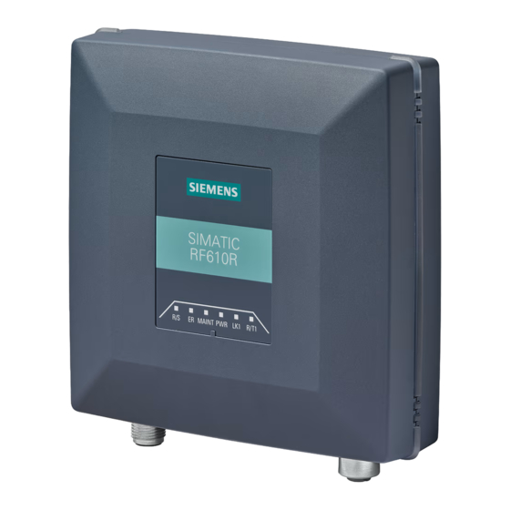
System components of the RF600 product series Pr r oduct photo Description SIMATIC RF610R RF610R reader is suitable for applications in production logistics and distribution. It is charac- terized by a very compact size - with reduced transmit power – as well as an internal anten- It is integrated for distribution via Ethernet with the XML protocol or OPC UA. - Page 28 System overview of SIMATIC RF600 3.2 System components P P r r oduct photo D D escription S S IMATIC RF650M The RF650M mobile reader expands the identification system RF600 with a powerful handheld terminal for applications in the areas of logistics, production and service. In addi- tion, it is an indispensable aid for commissioning and testing.
- Page 29 System overview of SIMATIC RF600 3.2 System components P P r r oduct photo D D escription S S IMATIC RF660A SIMATIC RF660A is a powerful circular antenna for production and logistics applications. S S IMATIC RF680A SIMATIC RF680A is an antenna whose polarization can be changed (circular, linear horizon- tal or linear vertical) of medium size for universal use in industrial applications in production and logistics.
-
Page 30: Features
External antenna < 8 m PROFIBUS external antennas Depends on the connected antenna and the transponder being used Certificates RF600 readers support the following certificates and approvals: RF610R certificate (https://support.industry.siemens.com/cs/ww/en/ps/25390/cert) RF615R certificates (https://support.industry.siemens.com/cs/ww/en/ps/25391/cert) RF650R certificates (https://support.industry.siemens.com/cs/ww/en/ps/15085/cert) RF680R/RF685R certificates (https://support.industry.siemens.com/cs/ww/en/ps/15088/cert) SIMATIC RF600... - Page 31 System overview of SIMATIC RF600 3.3 Features Table 3- 4 Characteristics of the RF650M mobile reader T T ransmission frequency ETSI: 865 to 868 MHz FCC: 902 to 928 MHz CMIIT: 920 to 925 MHz R R ead/write distance S S tandards ISO 18000-63 Table 3- 5 Characteristics of the transponders...
- Page 32 System overview of SIMATIC RF600 3.3 Features SIMATIC RF600 System Manual, 06/2019, J31069-D0171-U001-A22-7618...
-
Page 33: Rf600 System Planning
R R F600 system planning 4 4 .1 Overview You should observe the following criteria for implementation planning: Possible system configurations Antenna configurations Environmental conditions for transponders The response of electromagnetic waves in the UHF band Regulations applicable to frequency bands EMC Directives Possible system configurations The SIMATIC RF600 system is characterized by a high level of standardization of its... - Page 34 RF600 system planning 4.2 Possible system configurations F F eatures of the scenario Intralogistics (material flow) Figure 4-1 Scenario: Intralogistics (material flow) The conveyor transports the transport containers past the antennas. The transponders attached to the transport containers are always evenly aligned. The transponders in this scenario are transponders of the type SIMATIC RF630L.
- Page 35 The maximum transport speed of the conveyor belt is 2 m/s. In this scenario, a SIMATIC RF615R with a SIMATIC RF650A and a SIMATIC RF610R external antenna are used as the readers. These readers are inexpensive and feature a very compact design.
-
Page 36: Scenario For Workpiece Identification
RF600 system planning 4.2 Possible system configurations 4 4 .2.2 Scenario for workpiece identification A typical characteristic of modern manufacturing scenarios is their multitude of variations. The individual data and production steps are stored in the transponder of a tool holder or product. -
Page 37: Goods Tracking Scenario
RF600 system planning 4.2 Possible system configurations identification quality of the wanted transponders while reducing the identification of unwanted transponders. 4 4 .2.3 Goods tracking scenario In this scenario, a gate consisting of a SIMATIC RF650R reader and four antennas checks the goods passing through the gate. -
Page 38: Scenario Incoming Goods, Distribution Of Goods And Outgoing Goods
RF600 system planning 4.2 Possible system configurations 4 4 .2.4 Scenario incoming goods, distribution of goods and outgoing goods The scenario consists of an RFID system with three readers. The SIMATIC RF650R reader with its four antennas identifies the incoming/outgoing products at the incoming/outgoing goods gates of a factory building hall through which pallets are delivered. -
Page 39: Antenna Configurations
RF600 system planning 4.3 Antenna configurations F F eatures of the scenario In this example scenario, the SIMATIC RF685R reader is controlled by a light barrier and monitors a conveyor belt; the conveyor belt transports the goods towards two output gates that are assigned to different recipients. -
Page 40: Antenna Configuration Example
RF600 system planning 4.3 Antenna configurations 4 4 .3.1 Antenna configuration example The following figure shows an example of an application with an antenna configuration of the RF650R. The antennas are positioned at the height at which the transponders to be identified are expected. -
Page 41: Possibilities And Application Areas For Antenna Configurations
RF600 system planning 4.3 Antenna configurations 4 4 .3.2 Possibilities and application areas for antenna configurations Some basic antenna configurations and possible fields of application are shown below. With the various configurations, please note that up to four external antennas can be connected to the RF650R and RF680R readers, while one external antenna can be connected to the RF615 and RF685R readers. - Page 42 RF600 system planning 4.3 Antenna configurations A A ntenna configuration 2 D D escription/ application areas This arrangement of antennas is appro- priate when the transponders to be read are only located on one side of the items to be identified, e.g. when pallets are to be identified and it is known on which side the transponders to be read are located.
- Page 43 RF600 system planning 4.3 Antenna configurations A A ntenna configuration 4 D D escription/ application areas Preferred for the identification of goods at loading gates: Similar to configuration 2, but with additional reading reliability when the transponder is at an angle to the vertical.
- Page 44 RF600 system planning 4.3 Antenna configurations A A ntenna configuration 6 D D escription/ application areas Preferred for the identification of goods at loading gates: Similar to configuration 4, but the reliability of transponder identi- fication is improved as a result of the four antennas at separate locations, so the transponder position is not critical.
-
Page 45: Transponder Orientation In Space
RF600 system planning 4.3 Antenna configurations 4 4 .3.3 Transponder orientation in space The alignment of the transponder antenna to the antenna of the reader influences the reading range. For maximum performance and to achieve the maximum read range, the transponder antenna should therefore be aligned parallel to the reader antenna: Parallel transponder alignment Large reading range... -
Page 46: Specified Minimum And Maximum Spacing Of Antennas
RF600 system planning 4.3 Antenna configurations 4 4 .3.4 Specified minimum and maximum spacing of antennas Specified minimum spacing of antennas The following diagram shows the specified minimum and maximum spacings for mounting antennas: Between the antenna and liquids or metals, a minimum distance of 50 cm should be kept to. The distance between the antenna and the floor should also be at least 50 cm. -
Page 47: Reciprocal Influence Of Read Points
RF600 system planning 4.3 Antenna configurations 4 4 .3.5 Reciprocal influence of read points Antenna alignment and resulting antenna spacing The minimum distance required between antennas that use the same frequency and that are connected to different readers depends on the maximum transmit power set and the antenna alignment. -
Page 48: Read And Write Range
RF600 system planning 4.3 Antenna configurations A A ntenna spacing with portal configuration In the portal configuration, multiple antennas are connected to one reader. In this case, the antennas must not exceed the maximum distance to one another. Table 4- 2 Maximum antenna spacing of the external antennas with a portal configuration Antenna Antenna alignment... -
Page 49: Static/Dynamic Mode
RF600 system planning 4.3 Antenna configurations F F actors D D escription Reflection characteristics of the envi- In a multiple-reflection environment (e.g., in rooms with ronment reflecting surfaces, machinery, or concrete walls), the read- ing range can be significantly higher than in a low-reflection environment. -
Page 50: Operation Of Several Readers Within Restricted Space
RF600 system planning 4.3 Antenna configurations 4 4 .3.8 Operation of several readers within restricted space 4.3.8.1 Using more than one reader When mounting the readers make sure that there is a minimum clearance of 0.5 m between the readers to avoid them influencing each other. Avoiding problems When several RFID readers are used, there is a danger that RFID transponders can also be read out by other readers. -
Page 51: Frequency Hopping
RF600 system planning 4.3 Antenna configurations 4 4 .3.8.3 Frequency hopping This technique is intended to prevent mutual interference between readers. The reader changes its transmission channel in a random or programmed sequence (FHSS). Procedure for FCC Frequency hopping is always active in the FCC country profile. With 50 available channels the probability is low that two readers will be operating on the same frequency. -
Page 52: General Application Planning
RF600 system planning 4.3 Antenna configurations P P urpose of this chapter This section will help you to select the suitable antenna or the suitable cable taking into account all important criteria and to make the relevant settings in the configuration software/WBM of the SIMATIC RF600 system. -
Page 53: Types Of Antenna
With the readers, the parameters for the transmit/radiated power, antenna gain and cable loss (user-defined) are set using the WBM. In the WBM, you can select the Siemens products being used from a drop-down list quickly and easily, and the values and their effect on the transmit/radiated power are calculated directly. - Page 54 RF600 system planning 4.3 Antenna configurations A A ntenna cable loss In order to be able to transmit the available UHF power from the RF600 reader to the antenna or antennas, the antenna cable loss should not exceed a value of approx. 5 dB. Dependency of the cable loss The cable loss depends on two important factors: External characteristics of cable.
-
Page 55: Minimum Distances And Maximum Ranges
RF600 system planning 4.4 Minimum distances and maximum ranges 4 4 .4 Minimum distances and maximum ranges The following section describes the configuration of the antenna and transponder relative to each other. The aim of the section is to help you achieve the maximum ranges listed here in a typical electromagnetic environment. - Page 56 RF600 system planning 4.4 Minimum distances and maximum ranges With the antenna types with linear polarization (RF620A and RF642A), the polarization axes of the antenna and of the transponder must be aligned parallel to each other to achieve a maximum range. N N OTICE R R eduction of the maximum read/write range when using linear antennas If the alignment of the polarization axes of linear antennas (RF620A or RF642A) and...
- Page 57 RF600 system planning 4.4 Minimum distances and maximum ranges L L inear antennas To achieve the maximum range with linear antennas, make sure that the polarization axes of the antenna and transponder are parallel to each other. Changing the transponder angle within the x-y plane leads to a reduction of the range.
-
Page 58: Effects Of The Materials Of The Mounting Surfaces On The Range
RF600 system planning 4.4 Minimum distances and maximum ranges S S uboptimal transponder alignment for all antenna types If the angle is changed within the y-z plane, this causes a reduction in range for all antenna types. Antenna RF615A, RF620A, RF640A, RF642A, RF650A or RF680A Transponder Figure 4-13 Suboptimal transponder alignment... -
Page 59: Maximum Read/Write Ranges Of Transponders
RF600 system planning 4.4 Minimum distances and maximum ranges E E ffects due to transponder mounting The maximum read/write range of the transponders depends on the material of the mounting surface. The specified ranges apply when mounted on non-metallic surfaces, such as paper or card, with the RF640L, RF642L, RF625T, RF630T, RF640T and RF645T when mounted on metal. - Page 60 SIMATIC RF630L SIMATIC RF630L 6 6 GT2810- - 2AB01- 6 6 GT2810-2AB02- 6 6 GT2810-2AB03 6 6 GT2810-2AB04 0AX1 0AX0 SIMATIC RF610R S S IMATIC RF615R with internal antenna SIMATIC RF615R with RF615A with RF620A with RF640A with RF642A with RF650A...
- Page 61 RF600 system planning 4.4 Minimum distances and maximum ranges Table 4- 5 Read range of the transponders II (all ranges in meters [m]) S S IMATIC RF6 6 30L S S IMATIC RF630L S S IMATIC RF630L 6 6 GT2810- - 2 2 AC82 6 6 GT2810- - 2 2 AE80- - 0 0 AX2 6 6 GT2810- - 2 2 AE81- - 0 0 AX1 S S IMATIC RF610R...
- Page 62 Read range of the transponders III (all ranges in meters [m]) 1 1 ) S S IMATIC RF640L SIMATIC RF642L SIMATIC RF690L SIMATIC RF610T SIMATIC RF610R S S IMATIC RF615R with internal antenna SIMATIC RF615R with RF615A with RF620A with RF640A...
- Page 63 Read range of the transponders IV (all ranges in meters [m]) S S IMATIC RF620T 1 1 ) SIMATIC RF625T SIMATIC RF630T SIMATIC RF640T SIMATIC RF610R S S IMATIC RF615R with internal antenna SIMATIC RF615R with RF615A with RF620A with RF640A...
- Page 64 Table 4- 8 Read range of the transponders V (all ranges in meters [m]) 1 1 ) S S IMATIC RF645T SIMATIC RF680T SIMATIC RF682T SIMATIC RF610R S S IMATIC RF615R with internal antenna SIMATIC RF615R with RF615A with RF620A...
-
Page 65: Minimum Distances Between Antennas And Transponders
RF600 system planning 4.4 Minimum distances and maximum ranges 4 4 .4.4 Minimum distances between antennas and transponders The antennas listed here are all far field antennas. For this reason, a minimum distance between antennas and transponders must be maintained to ensure reliable transponder data access: Table 4- 9 Minimum distances to be maintained between antennas and transponders... -
Page 66: Environmental Conditions For Transponders
RF600 system planning 4.5 Environmental conditions for transponders 4 4 .5 Environmental conditions for transponders Basic rules The transponder must not be placed directly on metal surfaces or on containers of liquid. The on-metal transponders designed specifically for use in metallic environments are an exception to this. -
Page 67: Influence Of Metals
RF600 system planning 4.6 The response of electromagnetic waves in the UHF band R R educing the effect of reflections/interference on transponder identification Reducing the transmit power: To minimize interference, we recommend that the transmit power of the reader is reduced until it is sufficient for an identification rate of 100%. -
Page 68: Influence Of Liquids And Non-Metallic Substances
RF600 system planning 4.6 The response of electromagnetic waves in the UHF band This effect depends very much on the transmitted power, the components being used (cable, antenna) and the distance from the metallic surface to the antenna. In this case, repositioning/realigning the antenna or reducing the radiated power can remedy the situation. -
Page 69: Planning And Installation Of Uhf Read Points
RF600 system planning 4.7 Planning and installation of UHF read points 4 4 .7 Planning and installation of UHF read points Due to their comparatively large effective range, RFID UHF systems (frequency band 865 - 928 MHz) have different requirements in terms of planning, commissioning and operation compared with the HF systems commonly used up to now in automation (frequency band 13.56 MHz). - Page 70 RF600 system planning 4.7 Planning and installation of UHF read points distance between antenna and transponder, reflections, noise level in the channel used and in neighboring channels The RSSI value is important for the automatic evaluation of the read point and for filtering. A simple comparison of the RSSI values of two transponders is nevertheless not possible because the values are influenced by the transponder tolerances and the non-homogeneous antenna field.
- Page 71 RF600 system planning 4.7 Planning and installation of UHF read points P P roperties of the transmitting antenna Depending on their design, UHF RFID antennas provide different properties. They differ in the polarization and antenna gain. The direction of the electrical field component of an electromagnetic wave and the alignment of the antenna decide the polarization of the radiation.
-
Page 72: Implementation Of Uhf Rfid Installations
RF600 system planning 4.7 Planning and installation of UHF read points 4 4 .7.2 Implementation of UHF RFID installations The use of UHF RFID systems requires careful planning and preparation to avoid problems during commissioning and operation. 4.7.2.1 Preparation phase Device selection When selecting the suitable RFID hardware, remember the following minimum criteria: Integration in a control/IT environment... -
Page 73: Test Phase
RF600 system planning 4.7 Planning and installation of UHF read points D D ynamic identification Dead spots cannot be excluded. To be able to compensate for dead spots, we recommend that you give preference to dynamic identification rather than static identification. Dynamic identification means that the transponders are read while they are moving (e.g. -
Page 74: Setting Up Read Points
The read point setup described in this section is performed using the Web Based Management (WBM) and applies to the RF600 readers. You can find a detailed description of the WBM in the configuration manual "SIMATIC RF600 (https://support.industry.siemens.com/cs/ww/en/ps/15081/man)". Adjust antennas Follow the steps below to optimize the antenna alignment: 1. - Page 75 RF600 system planning 4.7 Planning and installation of UHF read points 4. In the "RSSI display" area, you can see the current (light blue) and maximum reached (dark blue) RSSI values. N N ote T T rans s ponder is not identified If no transponder is identified, first increase the radiated power as described in the following section.
- Page 76 RF600 system planning 4.7 Planning and installation of UHF read points D D etect activation power Follow the steps below to detect the activation power: 1. In the "Settings - Activation power" menu item, select the connected antenna and click the "Start measurement"...
-
Page 77: Dealing With Field Disturbances
RF600 system planning 4.7 Planning and installation of UHF read points 4 4 .7.3 Dealing with field disturbances 4.7.3.1 Types and approaches to solutions The superposition of radio waves and reflection by conductive materials (in particular metal) can lead to weakening or strengthening of the antenna field at certain points in space. These effects can lead to disruptions when identifying RFID transponders that can be distinguished as follows: Overshoots due to increasing field strength: Transponders are detected that are actually... -
Page 78: Measures For Eliminating Field Disturbances
RF600 system planning 4.7 Planning and installation of UHF read points Reader reader influence: Several readers influence or disturb each other during transponder identification. Approaches to solutions: – "Interconnect" neighboring readers so that they do not send at the same time –... - Page 79 RF600 system planning 4.7 Planning and installation of UHF read points C C hannel management To operate the readers, depending on the country profile, you have between four and fifty send channels available. Ideally, you should make the channel assignments manually in STEP 7 Basic / Professional (TIA Portal) or in the WBM.
-
Page 80: Chemical Resistance Of The Readers And Transponders
Aluminum Fiber-optic cable Makrolon®2405 Decorative membrane Autotex V200 Socket Brass (copper alloy) CuZn40Pb2 Non-relevant component for resistance of complete housing In case of questions please contact Siemens Support (section "Service & support (Page 506)"). SIMATIC RF600 System Manual, 06/2019, J31069-D0171-U001-A22-7618... -
Page 81: Pocan Cf2200
RF600 system planning 4.8 Chemical resistance of the readers and transponders 4 4 .8.1.2 Pocan CF2200 The following table provides an overview of the chemical resistance of the Pocan CF2200. Table 4- 11 Resistance to chemicals - Pocan CF2200 Substance Test conditions Evaluation Concentration [%]... - Page 82 RF600 system planning 4.8 Chemical resistance of the readers and transponders S S ubstance T T est conditions E E valuation C C oncentration [%] T T emperature [°C] C C leaning products Curd soap ++++ Detergent ++++ Cleaning products ++++ S S alt solutions Sodium hypochloride...
-
Page 83: Transponder
RF600 system planning 4.8 Chemical resistance of the readers and transponders 4 4 .8.2 Transponder 4.8.2.1 Overview of the transponders and their housing materials The following sections describe the resistance to chemicals of the various transponders. Resistance to chemicals depends on the housing materials used to manufacture the transponders. -
Page 84: Polyamide 12 (Pa12)
RF600 system planning 4.8 Chemical resistance of the readers and transponders S S ubstance T T est conditions E E valuation C C once e ntration [%] T T emperature [°C] Aromatic hydrocarbons Weak alkaline solutions ++++ Strong alkaline solutions ++++ Weak mineral acids ++++... - Page 85 RF600 system planning 4.8 Chemical resistance of the readers and transponders S S ubstance T T est conditions E E valuation C C oncentration [%] T T emperature [°C] n(n) ++++ Calcium chloride, w. ++++ Calcium nitrate, w. c. s. ++++ c.
-
Page 86: Polyamide 6.6 (Pa 6.6)
RF600 system planning 4.8 Chemical resistance of the readers and transponders S S ubstance T T est conditions E E valuation C C oncentration [%] T T emperature [°C] Hydrogen sulfide ++++ Carbon tetrachloride ++++ Toluene ++++ Detergent high ++++ Plasticizer ++++ E E xplanation of the rating... -
Page 87: Polyamide 6.6 Gf (Pa 6.6 Gf)
RF600 system planning 4.8 Chemical resistance of the readers and transponders S S ubstance T T est co o nditions E E valuation C C oncentration [%] T T emperature [°C] Trichloroethylene ++++ Hot water (hydrolysis resistance) E E xplanation of the rating ++++ Resistant Practically resistant... - Page 88 RF600 system planning 4.8 Chemical resistance of the readers and transponders S S ubstance T T est conditions E E valuation C C on n centration [%] T T emperature [°C] Magnesium salts, w. ++++ Methyl alcohol, w. 50 % ++++ Lactic acid, w.
-
Page 89: Polyethylene Terephthalate (Pet)
RF600 system planning 4.8 Chemical resistance of the readers and transponders 4 4 .8.2.6 Polyethylene terephthalate (PET) The following table provides an overview of the chemical resistance of the transponder made of polyethylene terephthalate. Table 4- 17 Chemical resistance - polyethylene terephthalate Substance Test conditions Evaluation... - Page 90 RF600 system planning 4.8 Chemical resistance of the readers and transponders S S ubstance T T est conditions E E valuation C C oncentration [%] T T emperature [°C] Lactic acid 10 % ++++ Sodium chloride 10 % ++++ Antichlor 10 % ++++ Paraffin oil...
-
Page 91: Polypropylene (Pp)
RF600 system planning 4.8 Chemical resistance of the readers and transponders 4 4 .8.2.7 Polypropylene (PP) The following table provides an overview of the chemical resistance of the transponder made of polyethylene terephthalate. Table 4- 18 Chemical resistance - polypropylene Substance Test conditions Evaluation... - Page 92 RF600 system planning 4.8 Chemical resistance of the readers and transponders S S ubstance T T est conditions E E valuation C C oncentration [%] T T emperature [°C] Calcium chloride, w./ alcoholic ++++ 50 °C Calcium chloride, 50 °C ++++ Calcium nitrate, w.
- Page 93 RF600 system planning 4.8 Chemical resistance of the readers and transponders S S ubstance T T est conditions E E valuation C C oncentration [%] T T emperature [°C] Magnesium salts 50 °C ++++ Machine oil 100 % ++++ Sea water 50 °C ++++ Methanol...
- Page 94 RF600 system planning 4.8 Chemical resistance of the readers and transponders S S ubstance T T est conditions E E valuation C C oncentration [%] T T emperature [°C] Sulfur dioxide 50 °C ++++ moist ++++ moist 50 °C liquid 50 °C Sulfuric acid 1 ...
-
Page 95: Polyphenylene Sulfide (Pps)
RF600 system planning 4.8 Chemical resistance of the readers and transponders 4 4 .8.2.8 Polyphenylene sulfide (PPS) The following table provides an overview of the chemical resistance of the transponder made of polyphenylene sulfide (PPS). The transponder has special chemical resistance to solutions up to a temperature of 200 °C. -
Page 96: Polyvinyl Chloride (Pvc)
RF600 system planning 4.8 Chemical resistance of the readers and transponders E E xplanation of the rating ++++ Resistant Practically resistant Conditionally resistant Less resistant Not resistant 4 4 .8.2.9 Polyvinyl chloride (PVC) The following table provides an overview of the chemical resistance of the transponder made of polyvinyl chloride (PVC). -
Page 97: Regulations Applicable To Frequency Bands
You will find the current country-specific frequency bands and approvals on the following Internet page: EPCglobal (http://www.gs1.org/docs/epcglobal/UHF_Regulations.pdf) You will find a list of all the country-specific approvals for SIMATIC RFID systems on the following Internet page: Wireless approvals of SIMATIC RFID systems (http://www.siemens.com/rfid-approvals) 4.10 Guidelines for electromagnetic compatibility (EMC) 4.10.1 Overview... -
Page 98: What Does Emc Mean
RF600 system planning 4.10 Guidelines for electromagnetic compatibility (EMC) 4 4 .10.2 What does EMC mean? The increasing use of electrical and electronic devices is accompanied by: Higher component density More switched power electronics Increasing switching rates Lower power consumption of components due to steeper switching edges The higher the degree of automation, the greater the risk of interaction between devices. -
Page 99: Basic Rules
RF600 system planning 4.10 Guidelines for electromagnetic compatibility (EMC) 4 4 .10.3 Basic rules It is often sufficient to follow a few elementary rules in order to ensure electromagnetic compatiblity (EMC). The following rules must be observed: Shielding by enclosure Protect the device against external interference by installing it in a cabinet or housing. -
Page 100: Propagation Of Electromagnetic Interference
RF600 system planning 4.10 Guidelines for electromagnetic compatibility (EMC) Feed the connected shield through to the module without interruption. Use braided shields, not foil shields. L L ine and signal filter Use only line filters with metal housings Connect the filter housing to the cabinet chassis using a large-area low-HF-impedance connection. - Page 101 RF600 system planning 4.10 Guidelines for electromagnetic compatibility (EMC) I I nterference sources In order to achieve a high level of electromagnetic compatibility and thus a very low level of disturbance in a plant, it is necessary to recognize the most frequent interference sources. These must then be eliminated by appropriate measures.
-
Page 102: Equipotential Bonding
RF600 system planning 4.10 Guidelines for electromagnetic compatibility (EMC) I I nterference source C C ause R R emedy HF interference over the caused by another reader Position the antennas further antennas apart. Erect suitable damping materials between the antennas. Reduce the power of the readers. -
Page 103: Cable Shielding
RF600 system planning 4.10 Guidelines for electromagnetic compatibility (EMC) The better the equipotential bonding in a plant, the smaller the chance of interference due to fluctuations in potential. Equipotential bonding should not be confused with protective earthing of a plant. Protective earthing prevents the occurrence of excessive contact voltages in the event of equipment faults whereas equipotential bonding prevents the occurrence of differences in potential. - Page 104 RF600 system planning 4.10 Guidelines for electromagnetic compatibility (EMC) Figure 4-22 Connection of shielding bus The shielding bus must be connected to the PE busbar. If shielded cables have to be interrupted, the shield must be continued via the corresponding connector housing.
-
Page 105: Readers
R R eaders 5 5 .1 Overview The following table shows the most important features of the stationary RF600 readers at a glance: Table 5- 1 Characteristics of the readers Characteristics SIMATIC SIMATIC SIMATIC SIMATIC SIMATIC R R F610R R R F615R R R F650R R R F680R R R F685R... - Page 106 Readers 5.1 Overview C C haracteristics S S IMATIC S S IMATIC S S IMATIC S S IMATIC S S IMATIC R R F610R R R F615R R R F650R R R F680R R R F685R Max. radiated power 200 mW ERP 200 mW ERP 2 W ERP 2 W ERP...
-
Page 107: Simatic Rf610R
Description 5.2.1.1 Overview The SIMATIC RF610R is a stationary reader in the UHF frequency band with an integrated antenna. The maximum transmit power is 400 mW, the radiant power of the internal antenna is 200 or 250 mW ERP / 400 mW EIRP. The interfaces (Ethernet, power supply) are located on the lower front edge. -
Page 108: Ordering Data
Readers 5.2 SIMATIC RF610R 5 5 .2.1.2 Ordering data Table 5- 2 RF610R ordering data Product Article number RF610R (ETSI) 6GT2811-6BC10-0AA0 RF610R (FCC) 6GT2811-6BC10-1AA0 RF610R (CMIIT) 6GT2811-6BC10-2AA0 Table 5- 3 Ordering data accessories Product Article number SIMATIC antenna holder for RF600 devices... -
Page 109: Pin Assignment Of The Power Supply Interface (X80 24Vdc)
Readers 5.2 SIMATIC RF610R 5 5 .2.1.3 Pin assignment of the power supply interface (X80 24VDC) Table 5- 4 Pin assignment of the RS422 interface (reader end) View of interface Wire colors Assignment ( ( M12 socket, 8-p p in) -
Page 110: Pin Assignment Of The Industrial Ethernet Interface (X1 P1)
Readers 5.2 SIMATIC RF610R N N OTICE F F or long cables: Adapt the power supply and transmission speed Note that even with long cables, the supply voltage of 24 VDC must always be guaranteed. Note also that the transmission speed on the serial interface must, if necessary, be reduced. - Page 111 Readers 5.2 SIMATIC RF610R D D ense Reader Mode (DRM) The readers can also interfere with each other (secondary fields), if the channels (Reader TX, Transponder TX) overlap. In order to prevent a transponder channel overlapping with a reader channel, we recommend that the Dense Reader Mode (DRM) is used.
- Page 112 Readers 5.2 SIMATIC RF610R R R adiation diagram (ETSI) Pattern of the vertical plane of the antenna Pattern of the horizontal plane of the antenna Figure 5-2 Directional radiation pattern of RF610R in the ETSI frequency band SIMATIC RF600 System Manual, 06/2019, J31069-D0171-U001-A22-7618...
- Page 113 Readers 5.2 SIMATIC RF610R O O verview of the antenna parameters Table 5- 6 Maximum linear electrical aperture angle at 865 MHz: Polarization (circular) Azimuth section 100° Elevation section 100° Typical antenna gain -1 dBi in the frequency band 865 to 868 MHz...
- Page 114 Readers 5.2 SIMATIC RF610R R R adiation diagram (FCC) Pattern of the vertical plane of the antenna Pattern of the horizontal plane of the antenna Figure 5-4 Directional radiation pattern of RF610R in the FCC frequency band SIMATIC RF600 System Manual, 06/2019, J31069-D0171-U001-A22-7618...
-
Page 115: Interpretation Of Radiation Patterns
Readers 5.2 SIMATIC RF610R O O verview of the antenna parameters Table 5- 7 Maximum linear electrical aperture angle at 915 MHz: Polarization (circular) Azimuth section 100° Elevation section 100° Typical antenna gain 0 dBi in the frequency band 902 to 928 MHz... -
Page 116: Configuration/Integration
Readers 5.2 SIMATIC RF610R 5 5 .2.4 Configuration/integration An Ethernet interface is available for integrating the device into system environments/networks. RF610R can be configured via the Ethernet interface and with direct connection to the PC. You can configure and program the reader using the following tools:... -
Page 117: Technical Specifications
Readers 5.2 SIMATIC RF610R 5 5 .2.5 Technical specifications Table 5- 8 Technical specifications of the RF610R reader 6GT2811- - 6BC10- - xAA0 Product type designation SIMATIC RF610R Radio frequencies Operating frequency ETSI 865 to 868 MHz 902 to 928 MHz... - Page 118 Readers 5.2 SIMATIC RF610R 6 6 GT2811- - 6 6 BC10- - x x AA0 Typical transmission time per byte Write access 2 ms Read access 0.15 ms Supply voltage 24 VDC (20 ... 30 VDC) Maximum permitted current consumption 0.3 A...
- Page 119 Readers 5.2 SIMATIC RF610R 6 6 GT2811- - 6 6 BC10- - x x AA0 D D esign, dimensions and weight Dimensions (W × H × D) 140.5 × 133 × 45 mm Weight 370 g Type of mounting VESA 100 4x screws M4 ( 1.5 Nm)
-
Page 120: Dimension Drawing
Readers 5.2 SIMATIC RF610R 5 5 .2.6 Dimension drawing Figure 5-6 Dimension drawing RF610R All dimensions in mm (± 0.5 mm tolerance) SIMATIC RF600 System Manual, 06/2019, J31069-D0171-U001-A22-7618... -
Page 121: Certificates And Approvals
Readers 5.2 SIMATIC RF610R 5 5 .2.7 Certificates and approvals 5.2.7.1 CE mark Note M M arking on the readers according to specific approval The certificates and approvals listed here apply only if the corresponding mark is found on the readers. -
Page 122: Fcc Information
Readers 5.2 SIMATIC RF610R 5 5 .2.7.3 FCC information Siemens SIMATIC RF610R (FCC): 6GT2811-6BC10-1AA0 FCC ID: NXW-RF610R This device complies with part 15 of the FCC rules. Operation is subject to the following two conditions: (1) This device may not cause harmful interference, and (2) this device must accept any interference received, including interference that may cause undesired operation. -
Page 123: Ic-Fcb Information
Readers 5.2 SIMATIC RF610R 5 5 .2.7.4 IC-FCB information Siemens SIMATIC RF610R (FCC): 6GT2811-6BC10-1AA0 IC: 267X-RF610R This device complies with Industry Canada licence-exempt RSS standard(s). Operation is subject to the following two conditions: (1) This device may not cause interference, and (2) this device must accept any interference, including interference that may cause undesired operation of the device. -
Page 124: Simatic Rf615R
Readers 5.3 SIMATIC RF615R 5 5 .3 SIMATIC RF615R 5.3.1 Description 5.3.1.1 Overview The SIMATIC RF615R is a stationary reader in the UHF frequency band with an integrated antenna. An external UHF RFID antenna can be connected via an RP-TNC connector. The maximum transmit power is 400 mW, the radiant power of the internal antenna is 200 or 250 mW ERP / 400 mW EIRP. -
Page 125: Ordering Data
Readers 5.3 SIMATIC RF615R 5 5 .3.1.2 Ordering data Table 5- 12 RF615R ordering data Product Article number RF615R (ETSI) 6GT2811-6CC10-0AA0 RF615R (FCC) 6GT2811-6CC10-1AA0 RF615R (CMIIT) 6GT2811-6CC10-2AA0 Table 5- 13 Ordering data accessories Product Article number SIMATIC antenna holder for RF600 devices 6GT2890-2AB10 Connecting cable and connectors 3RK1902-4BA00-5AA0... -
Page 126: Pin Assignment Of The Di/Dq Interface (X10 Di/Dq)
Readers 5.3 SIMATIC RF615R 5 5 .3.1.3 Pin assignment of the DI/DQ interface (X10 DI/DQ) Table 5- 14 Pin assignment of the DI/DQ interface (reader end) View of interface Pin assignment ( ( M12 socket, 5-p p in) DI Common / Input Common DO / Output DO Common / Output Common DI / Input... - Page 127 Readers 5.3 SIMATIC RF615R I I nput (DI) The input is set up with electrical isolation via optocoupler. Level – Low: 0 ... 7 V – High: 15 ... 24 V The following diagrams illustrate various connection possibilities. Note M M inimum time between changes Note that changes on the DI/DQ interface that are not applied for at least 1.5 seconds are not detected by the reader.
-
Page 128: Pin Assignment Of The Power Supply Interface (X80 24Vdc)
Readers 5.3 SIMATIC RF615R Voltage infeed from an external source is shown here for 12 V as an example. Other voltages are also permissible. 5 5 .3.1.5 Pin assignment of the power supply interface (X80 24VDC) Table 5- 15 Pin assignment of the RS422 interface (reader end) View of interface Wire colors Assignment... -
Page 129: Pin Assignment Of The Industrial Ethernet Interface (X1 P1)
Readers 5.3 SIMATIC RF615R N N otes on connectors and cables The cables with open cable ends (6GT2891-4EH20, 6GT2891-4EH50) have an 8-pin M12 plug at one end, while the other end of the cable is "open". There are 8 color-coded single wires there for connecting to external devices. -
Page 130: Planning Operation
Readers 5.3 SIMATIC RF615R 5 5 .3.2 Planning operation 5.3.2.1 Internal antenna Minimum mounting clearances of two readers RF615R has an internal circular antenna. To prevent the antenna fields from overlapping, always observe the recommended minimum distances between two readers as described in the section "Reciprocal influence of read points (Page 47)". - Page 131 Readers 5.3 SIMATIC RF615R A A ntenna diagram RF615R (ETSI) The following radiation diagrams show the directional characteristics of the internal antenna of the RF615R (ETSI) reader. For the spatial presentation of the directional characteristics, the horizontal plane (azimuth section) as well as the vertical plane (elevation section) must be considered.
- Page 132 Readers 5.3 SIMATIC RF615R R R adiation diagram (ETSI) Pattern of the vertical plane of the antenna Pattern of the horizontal plane of the antenna Figure 5-10 Directional radiation pattern of RF615R in the ETSI frequency band SIMATIC RF600 System Manual, 06/2019, J31069-D0171-U001-A22-7618...
- Page 133 Readers 5.3 SIMATIC RF615R O O verview of the antenna parameters Table 5- 17 Maximum linear electrical aperture angle at 865 MHz: Polarization (circular) Azimuth section 100° Elevation section 100° Typical antenna gain -1 dBi in the frequency band 865 to 868 MHz Antenna axis ratio 2 dB You will find more information on the antennas in the section "Guidelines for selecting RFID...
- Page 134 Readers 5.3 SIMATIC RF615R R R adiation diagram (FCC) Pattern of the vertical plane of the antenna Pattern of the horizontal plane of the antenna Figure 5-12 Directional radiation pattern of RF615R in the FCC frequency band SIMATIC RF600 System Manual, 06/2019, J31069-D0171-U001-A22-7618...
-
Page 135: External Antenna
Readers 5.3 SIMATIC RF615R O O verview of the antenna parameters Table 5- 18 Maximum linear electrical aperture angle at 915 MHz: Polarization (circular) Azimuth section 100° Elevation section 100° Typical antenna gain 0 dBi in the frequency band 902 to 928 MHz Antenna axis ratio 2 dB You will find more information on the antennas in the section "Guidelines for selecting RFID... -
Page 136: Installing/Mounting
Readers 5.3 SIMATIC RF615R 5 5 .3.3 Installing/mounting Requirement NOTICE Close unused connectors Note that the readers only have the specified degree of protection when all connectors are in use or when unused connectors are closed with the protective caps. CAUTION Emitted radiation The transmitter complies with the requirements of Health Canada and the FCC limit values... -
Page 137: Configuration/Integration
Readers 5.3 SIMATIC RF615R 5 5 .3.4 Configuration/integration An Ethernet interface is available for integrating the device into system environments/networks. RF615R can be configured via the Ethernet interface and with direct connection to the PC. You can configure and program the reader using the following tools: STEP 7 Basic/Professional (TIA Portal) or via EtherNet/IP Web Based Management (WBM) -
Page 138: Technical Specifications
Readers 5.3 SIMATIC RF615R 5 5 .3.5 Technical specifications Table 5- 19 Technical specifications of the RF615R reader 6GT2811- - 6CC10- - xAA0 Product type designation SIMATIC RF615R Radio frequencies Operating frequency ETSI 865 to 868 MHz 902 to 928 MHz CMIIT 920 to 925 MHz Transmit power... - Page 139 Readers 5.3 SIMATIC RF615R 6 6 GT2811- - 6 6 CC10- - x x AA0 Typical transmission time per byte Write access 2 ms Read access 0.15 ms Supply voltage 24 V DC (20 ... 30 V DC) Maximum permitted current consumption 0.3 A Maximum permitted current consumption via DI/DQ interface...
- Page 140 Readers 5.3 SIMATIC RF615R 6 6 GT2811- - 6 6 CC10- - x x AA0 P P ermitted ambient conditions Ambient temperature During operation -25 ... +55 °C During transportation and storage -40 ... +85 °C Conditions relating to UL approval for indoor use only (dry location) Mounting height shall be equal or less than 2 m (MS1 classification according UL/IEC...
-
Page 141: Dimension Drawing
Readers 5.3 SIMATIC RF615R 5 5 .3.6 Dimension drawing Figure 5-14 Dimension drawing RF615R All dimensions in mm (± 0.5 mm tolerance) SIMATIC RF600 System Manual, 06/2019, J31069-D0171-U001-A22-7618... -
Page 142: Certificates And Approvals
Readers 5.3 SIMATIC RF615R 5 5 .3.7 Certificates and approvals 5.3.7.1 CE mark Note M M arking on the readers according to specific approval The certificates and approvals listed here apply only if the corresponding mark is found on the readers. Table 5- 20 6GT2811-6CC10-0AA0 Labeling... -
Page 143: Fcc Information
Readers 5.3 SIMATIC RF615R 5 5 .3.7.3 FCC information Siemens SIMATIC RF615R (FCC): 6GT2811-6CC10-1AA0 FCC ID: NXW-RF615R This device complies with part 15 of the FCC rules. Operation is subject to the following two conditions: (1) This device may not cause harmful interference, and (2) this device must accept any interference received, including interference that may cause undesired operation. -
Page 144: Ic-Fcb Information
Readers 5.3 SIMATIC RF615R 5 5 .3.7.4 IC-FCB information Siemens SIMATIC RF615R (FCC): 6GT2811-6CC10-1AA0 IC: 267X-RF615R This device complies with Industry Canada licence-exempt RSS standard(s). Operation is subject to the following two conditions: (1) This device may not cause interference, and (2) this device must accept any interference, including interference that may cause undesired operation of the device. -
Page 145: Simatic Rf650R
Readers 5.4 SIMATIC RF650R 5 5 .4 SIMATIC RF650R 5.4.1 Description 5.4.1.1 Overview The SIMATIC RF650R is a stationary reader in the UHF frequency band without an integrated antenna. Up to four external UHF RFID antennas can be connected via RP-TNC connectors. -
Page 146: Ordering Data
Readers 5.4 SIMATIC RF650R 5 5 .4.1.2 Ordering data Table 5- 23 Ordering data RF650R Product Article number RF650R (ETSI) 6GT2811-6AB20-0AA0 RF650R (FCC) 6GT2811-6AB20-1AA0 RF650R (CMIIT) 6GT2811-6AB20-2AA0 RF650R (ARIB) 6GT2811-6AB20-4AA0 Table 5- 24 Ordering data accessories Product Article number Holders for securing the reader 6GT2890-0AB00 DIN rail T35 (S7-1200) S7-300 standard rail... -
Page 147: Pin Assignment Of The Di/Dq Interface (X10 Di/Dq)
Readers 5.4 SIMATIC RF650R P P roduct A A rticle number 24 V connecting cable reader wide-range power supply unit 6GT2891-0PH50 with plug, 5 m 6GT2891-4EH20 with open ends, 2 m 6GT2891-4EH50 with open ends, 5 m DVD "Ident Systems Software & Documentation" 6GT2080-2AA20 5 5 .4.1.3 Pin assignment of the DI/DQ interface (X10 DI/DQ) -
Page 148: Switching Scheme For The Di/Dq Interface
C C olor scheme of the DI/DQ standard cable with M12 connector The following figure shows the color scheme of the DI/DQ standard cable from Siemens (6GT2891-0CH50). You can use the color scheme to assign the wire colors to the pins. - Page 149 Readers 5.4 SIMATIC RF650R The following diagrams illustrate various connection possibilities. N N ote M M inimum t t ime between changes Note that changes on the DI/DQ interface that are not applied for at least 1.5 seconds are not detected by the reader. Voltage infeed from internal source (no electrical isolation) Figure 5-16 Circuit example 1: Digital inputs...
- Page 150 Readers 5.4 SIMATIC RF650R V V oltage infeed from external source Figure 5-17 Circuit example 2: Digital inputs Voltage infeed from external source with various voltages Figure 5-18 Circuit example 3: Digital inputs SIMATIC RF600 System Manual, 06/2019, J31069-D0171-U001-A22-7618...
- Page 151 Readers 5.4 SIMATIC RF650R V V oltage infeed from internal source Figure 5-19 Circuit example 4: Digital outputs Alternative connection possibilities: Pin 1 GND to Pin 3 DO Common Pin 2 (VCC) to busbar outputs SIMATIC RF600 System Manual, 06/2019, J31069-D0171-U001-A22-7618...
- Page 152 Readers 5.4 SIMATIC RF650R V V oltage infeed from external source Figure 5-20 Circuit example 5: Digital outputs Voltage infeed from an external source is shown here for 12 V as an example. Other voltages are also permissible. SIMATIC RF600 System Manual, 06/2019, J31069-D0171-U001-A22-7618...
- Page 153 Readers 5.4 SIMATIC RF650R V V oltage infeed from external source with various voltages Figure 5-21 Circuit example 6: Digital outputs 5.4.1.5 Pin assignment of the power supply interface (X80 24VDC) Table 5- 26 Pin assignment of the RS422 interface (reader end) View of interface Wire colors Assignment...
- Page 154 Readers 5.4 SIMATIC RF650R N N ote R R equirement for external power sources The reader must only be supplied with power by power supply units that meet the requirements of LPS (Limited Power Source) and NEC Class 2. R R equirement for external power sou u rces The reader must only be supplied with power by power supply units that meet the requirementsof limited power source (LPS) and NEC Class 2.
- Page 155 Note U U se of Siemens cables We recommend that you only use original Siemens cables and connectors (refer to the section "Ordering data (Page 146)") to connect to the Ethernet socket of the reader. If plug-in connectors from other manufacturers are used, it may be difficult or even impossible to remove the plug from the reader.
- Page 156 Readers 5.4 SIMATIC RF650R G G round connection Screw (M4 x 8) Flat washer Cable lug Contact washer 5 5 .4.2 Planning operation 5.4.2.1 Antenna/read point configurations You can connect up to four external antennas to the RF650R reader. The standard setting is that an antenna is connected when the reader is started.
- Page 157 Readers 5.4 SIMATIC RF650R 5 5 .4.3 Installation/mounting Requirement NOTICE Close unused connectors Note that the readers only have the specified degree of protection when all connectors are in use or when unused connectors are closed with the protective caps. CAUTION Emitted radiation The transmitter complies with the requirements of Health Canada and the FCC limit values...
- Page 158 Readers 5.4 SIMATIC RF650R M M ounting the reader on a DIN/standard rail Table 5- 28 DIN rail mounting Description 1. Place the spring in the groove. 2. Mount the holder using the supplied Torx screws. When mounting the holder, make sure that the angled tip is positioned above the spring in the groove.
- Page 159 Readers 5.4 SIMATIC RF650R D D escription 3. Fit the lower part of the locking mechanism of the reader into the DIN rail. To be able to mount the reader on or remove it from the DIN rail, pull down the holder mounted in step 2.
- Page 160 Readers 5.4 SIMATIC RF650R Table 5- 29 Installation on a standard rail D D escription 1. Mount the two adapter pieces using the supplied Torx screws. 2. Fit the upper part of the locking mechanism of the reader into the standard rail. 3.
- Page 161 Readers 5.4 SIMATIC RF650R 5 5 .4.4 Configuration/integration An Ethernet interface is available for integrating the device into system environments/networks. The RF650R can be configured via the Ethernet interface and with direct connection to the PC. You can configure and program the reader using the following tools: using Web Based Management (WBM) OPC UA or XML based user applications...
- Page 162 Readers 5.4 SIMATIC RF650R 5 5 .4.5 Technical specifications Table 5- 30 Technical specifications of the RF650R reader 6GT2811- - 6AB20- - xAA0 Product type designation SIMATIC RF650R Radio frequencies Operating frequency ETSI 865 to 868 MHz 902 to 928 MHz CMIIT 920 to 925 MHz ARIB (STD-T107)
- Page 163 Readers 5.4 SIMATIC RF650R 6 6 GT2811- - 6 6 AB20- - x x AA0 Channel spacing ETSI 600 kHz 500 kHz CMIIT 250 kHz ARIB (STD-T107) 200 kHz Modulation methods ASK: DSB modulation & PR-ASK modulation encoding, Manchester or Pulse Interval (PIE) Multitag capability Typical transmission time per byte Write access...
- Page 164 Readers 5.4 SIMATIC RF650R 6 6 GT2811- - 6 6 AB20- - x x AA0 M M echanical specifications Material Upper part of housing Pocan (silicone-free) Lower part of housing Aluminum Color Upper part of housing TI-Grey Lower part of housing Silver P P ermitted ambient conditions Ambient temperature...
- Page 165 Readers 5.4 SIMATIC RF650R 5 5 .4.6 Dimension drawing Figure 5-23 Dimension drawing RF650R All dimensions in mm (± 0.5 mm tolerance) SIMATIC RF600 System Manual, 06/2019, J31069-D0171-U001-A22-7618...
- Page 166 Readers 5.4 SIMATIC RF650R 5 5 .4.7 Certificates and approvals Note M M arking on the readers according to specific approval The certificates and approvals listed here apply only if the corresponding mark is found on the readers. Table 5- 31 6GT2811-6AB20-0AA0 Labeling Description...
- Page 167 Readers 5.4 SIMATIC RF650R L L abeling D D escription Brazil radio approval Marking on the reader (6GT2811-6AB20-1AA0): Statement about approval: Este equipamento opera em caráter secundário, isto é, não tem direito à proteção contra interferência prejudicial, mesmo de es- tações do mesmo tipo e não pode causar interferência a sistemas operando em caráter primário.
- Page 168 China radio approval Marking on the reader: CMIIT ID: 2014DJ3987 5 5 .4.7.1 FCC information Siemens SIMATIC RF650R (FCC): 6GT2811-6AB20-1AA0 FCC ID: NXW-RF600R2 This device complies with part 15 of the FCC rules. Operation is subject to the following two conditions:...
- Page 169 Readers 5.4 SIMATIC RF650R 5 5 .4.7.2 IC-FCB information Siemens SIMATIC RF650R (FCC): 6GT2811-6AB20-1AA0 IC: 267X-RF600R2 This device complies with Industry Canada licence-exempt RSS standard(s). Operation is subject to the following two conditions: (1) This device may not cause interference, and (2) this device must accept any interference, including interference that may cause undesired operation of the device.
- Page 170 Readers 5.5 SIMATIC RF680R 5 5 .5 SIMATIC RF680R 5.5.1 Description 5.5.1.1 Overview The SIMATIC RF680R is a stationary reader in the UHF frequency band without an integrated antenna. Up to four external UHF RFID antennas can be connected via RP-TNC connectors.
- Page 171 Readers 5.5 SIMATIC RF680R 5 5 .5.1.2 Ordering data Table 5- 34 Ordering data RF680R Product Article number RF680R (ETSI) 6GT2811-6AA10-0AA0 RF680R (FCC) 6GT2811-6AA10-1AA0 RF680R (CMIIT) 6GT2811-6AA10-2AA0 RF680R (ARIB) 6GT2811-6AA10-4AA0 Table 5- 35 Ordering data accessories Product Article number r Holder set for securing the reader 6GT2890-0AB00 DIN rail T35 (S7-1200)
- Page 172 Readers 5.5 SIMATIC RF680R P P roduct A A rticle number r Connecting cable CM reader / extension cable for 24 V connecting cable RS422, M12 connector, 8-pin socket 6GT2891-4FH20 6GT2891-4FH50 6GT2891-4FN10 10 m 6GT2891-4FN20 20 m 6GT2891-4FN50 50 m Wide-range power supply unit for SIMATIC RF systems 6GT2898-0AC00 With EU plug...
- Page 173 C C olor scheme of the DI/DQ standard cable with M12 connector The following figure shows the color scheme of the DI/DQ standard cable from Siemens (6GT2891-0CH50). You can use the color scheme to assign the wire colors to the pins.
- Page 174 Readers 5.5 SIMATIC RF680R i i nput (DI 0 ... 3) The inputs are optically isolated through optocouplers. Level – Low: 0 ... 7 V – High: 15 ... 24 V The following diagrams illustrate various connection possibilities. Note M M inimum time between changes Note that changes on the DI/DQ interface that are not applied for at least 1.5 seconds are not detected by the reader.
- Page 175 Readers 5.5 SIMATIC RF680R V V oltage infeed from external source Figure 5-26 Circuit example 2: Digital inputs Voltage infeed from external source with various voltages Figure 5-27 Circuit example 3: Digital inputs SIMATIC RF600 System Manual, 06/2019, J31069-D0171-U001-A22-7618...
- Page 176 Readers 5.5 SIMATIC RF680R V V oltage infeed from internal source Figure 5-28 Circuit example 4: Digital outputs Alternative connection possibilities: Pin 1 GND to Pin 3 DO Common Pin 2 (VCC) to busbar outputs SIMATIC RF600 System Manual, 06/2019, J31069-D0171-U001-A22-7618...
- Page 177 Readers 5.5 SIMATIC RF680R V V oltage infeed from external source Figure 5-29 Circuit example 5: Digital outputs Voltage infeed from an external source is shown here for 12 V as an example. Other voltages are also permissible. SIMATIC RF600 System Manual, 06/2019, J31069-D0171-U001-A22-7618...
- Page 178 Readers 5.5 SIMATIC RF680R V V oltage infeed from external source with various voltages Figure 5-30 Circuit example 6: Digital outputs 5.5.1.5 Pin assignment of the power supply interface (X80 24VDC) Table 5- 37 Pin assignment of the RS422 interface (reader end) View of interface Wire colors Assignment...
- Page 179 Readers 5.5 SIMATIC RF680R N N ote R R equiremen n t for external power sources The reader must only be supplied with power by power supply units that meet the requirements of LPS (Limited Power Source) and NEC Class 2. R R equirement for external power sources The reader must only be supplied with power by power supply units that meet the requirementsof limited power source (LPS) and NEC Class 2.
- Page 180 Readers 5.5 SIMATIC RF680R 5 5 .5.1.6 Pin assignment of the Industrial Ethernet interface (X1 P1; X1 P2) Table 5- 38 Pin assignment of the Industrial Ethernet interface (reader end) View of interface Pin assignment ( ( M12 socket, 4-p p in) Data line +Tx Data line +Rx Data line -Tx...
- Page 181 Readers 5.5 SIMATIC RF680R G G rou u nd connection Screw (M4 x 8) Flat washer Cable lug Contact washer 5 5 .5.2 Planning operation 5.5.2.1 Antenna/read point configurations You can connect up to four external antennas to the RF680R reader. The standard setting is that an antenna is connected when the reader is started.
- Page 182 Readers 5.5 SIMATIC RF680R 5 5 .5.3 Installation/mounting Requirement NOTICE Close unused connectors Note that the readers only have the specified degree of protection when all connectors are in use or when unused connectors are closed with the protective caps. Close any connectors on the reader that you are not using with protective caps.
- Page 183 Readers 5.5 SIMATIC RF680R 5 5 .5.3.1 Mounting/Installation Mounting/installing the device You can mount the reader in the following ways: DIN rail T35 (S7-1200) S7-300 standard rail S7-1500 standard rail directly on a flat surface using the VESA 100 mounting system (torque 1.5 Nm).
- Page 184 Readers 5.5 SIMATIC RF680R D D escription 2. Mount the holder using the supplied Torx screws. When mounting the holder, make sure that the angled tip is positioned above the spring in the groove. 3. Fit the lower part of the locking mechanism of the reader into the DIN rail.
- Page 185 Readers 5.5 SIMATIC RF680R Table 5- 40 Installation on a standard rail D D escription 1. Mount the two adapter pieces using the supplied Torx screws. 2. Fit the upper part of the locking mechanism of the reader into the standard rail. 3.
- Page 186 Readers 5.5 SIMATIC RF680R 5 5 .5.4 Configuration/integration An Ethernet interface is available for integrating the device into system environments/networks. The RF680R can be configured via the Ethernet interface and with direct connection to the PC. You can configure and program the reader using the following tools: STEP 7 Basic/Professional (TIA Portal) or via EtherNet/IP...
- Page 187 Readers 5.5 SIMATIC RF680R 5 5 .5.5 Technical specifications Table 5- 41 Technical specifications of the RF680R reader 6GT2811- - 6AA10- - xAA0 Product type designation SIMATIC RF680R Radio frequencies Operating frequency ETSI 865 to 868 MHz 902 to 928 MHz CMIIT 920 to 925 MHz ARIB (STD-T106)
- Page 188 Readers 5.5 SIMATIC RF680R 6 6 GT2811- - 6 6 AA10- - x x AA0 Channel spacing ETSI 600 kHz 500 kHz CMIIT 250 kHz ARIB (STD-T106) 1200 kHz Modulation methods ASK: DSB modulation & PR-ASK modulation encoding, Manchester or Pulse Interval (PIE) Multitag capability Typical transmission time per byte Write access...
- Page 189 Readers 5.5 SIMATIC RF680R 6 6 GT2811- - 6 6 AA10- - x x AA0 M M echanical specifications Material Upper part of housing Pocan (silicone-free) Lower part of housing Aluminum Color Upper part of housing TI-Grey Lower part of housing Silver P P ermitted ambient conditions Ambient temperature...
- Page 190 Readers 5.5 SIMATIC RF680R 6 6 GT2811- - 6 6 AA10- - x x AA0 S S tandards, specifications, approvals Proof of suitability EN 301 489-1 V1.9.2 / EN 301 489-3 V1.6.1 / EN 302 208-1/-3 V1.4.1 FCC CFR 47, Part 15 section 15.247 MTBF 28 years Measured at the output of the antenna socket.
- Page 191 Readers 5.5 SIMATIC RF680R 5 5 .5.7 Certificates and approvals Note M M arking on the readers according to specific approval The certificates and approvals listed here apply only if the corresponding mark is found on the readers. Table 5- 42 6GT2811-6AA10-0AA0 Labeling Descr r iption...
- Page 192 Readers 5.5 SIMATIC RF680R L L abeling D D escription Brazil radio approval Marking on the reader (6GT2811-6AA10-1AA0): Statement about approval: Este equipamento opera em caráter secundário, isto é, não tem direito à proteção contra interferência prejudicial, mesmo de es- tações do mesmo tipo e não pode causar interferência a sistemas operando em caráter primário.
- Page 193 Readers 5.5 SIMATIC RF680R 5 5 .5.7.1 FCC information Siemens SIMATIC RF680R (FCC): 6GT2811-6AA10-1AA0 FCC ID: NXW-RF600R2 This device complies with part 15 of the FCC rules. Operation is subject to the following two conditions: (1) This device may not cause harmful interference, and (2) this device must accept any interference received, including interference that may cause undesired operation.
- Page 194 Readers 5.5 SIMATIC RF680R 5 5 .5.7.2 IC-FCB information Siemens SIMATIC RF680R (FCC): 6GT2811-6AA10-1AA0 IC: 267X-RF600R2 This device complies with Industry Canada licence-exempt RSS standard(s). Operation is subject to the following two conditions: (1) This device may not cause interference, and (2) this device must accept any interference, including interference that may cause undesired operation of the device.
- Page 195 Readers 5.6 SIMATIC RF685R 5 5 .6 SIMATIC RF685R 5.6.1 Description 5.6.1.1 Overview The SIMATIC RF685R is a stationary reader in the UHF frequency band with an integrated antenna. An additional external UHF RFID antenna can be connected via an RP-TNC connector.
- Page 196 Readers 5.6 SIMATIC RF685R 5 5 .6.1.2 Ordering data Table 5- 45 Ordering data RF685R Pro o duct Article number RF685R (ETSI) 6GT2811-6CA10-0AA0 RF685R (FCC) 6GT2811-6CA10-1AA0 RF685R (CMIIT) 6GT2811-6CA10-2AA0 RF685R (ARIB) 6GT2811-6CA10-4AA0 Table 5- 46 Ordering data accessories Product Article number Holder set for securing the reader 6GT2890-0AB00 DIN rail T35 (S7-1200)
- Page 197 Readers 5.6 SIMATIC RF685R P P roduct A A rticle number Connecting cable CM reader / extension cable for 24 V connecting cable RS422, M12 connector, 8-pin socket 6GT2891-4FH20 6GT2891-4FH50 6GT2891-4FN10 10 m 6GT2891-4FN20 20 m 6GT2891-4FN50 50 m Wide-range power supply unit for SIMATIC RF systems 6GT2898-0AC00 With EU plug 6GT2898-0AC10...
- Page 198 C C olor scheme of the DI/DQ standard cable with M12 connector The following figure shows the color scheme of the DI/DQ standard cable from Siemens (6GT2891-0CH50). You can use the color scheme to assign the wire colors to the pins.
- Page 199 Readers 5.6 SIMATIC RF685R i i nput (DI 0 ... 3) The inputs are optically isolated through optocouplers. Level – Low: 0 ... 7 V – High: 15 ... 24 V The following diagrams illustrate various connection possibilities. Note M M inimum time between changes Note that changes on the DI/DQ interface that are not applied for at least 1.5 seconds are not detected by the reader.
- Page 200 Readers 5.6 SIMATIC RF685R V V oltage infeed from external source Figure 5-35 Circuit example 2: Digital inputs Voltage infeed from external source with various voltages Figure 5-36 Circuit example 3: Digital inputs SIMATIC RF600 System Manual, 06/2019, J31069-D0171-U001-A22-7618...
- Page 201 Readers 5.6 SIMATIC RF685R V V oltage infeed from internal source Figure 5-37 Circuit example 4: Digital outputs Alternative connection possibilities: Pin 1 GND to Pin 3 DO Common Pin 2 (VCC) to busbar outputs SIMATIC RF600 System Manual, 06/2019, J31069-D0171-U001-A22-7618...
- Page 202 Readers 5.6 SIMATIC RF685R V V oltage infeed from external source Figure 5-38 Circuit example 5: Digital outputs Voltage infeed from an external source is shown here for 12 V as an example. Other voltages are also permissible. SIMATIC RF600 System Manual, 06/2019, J31069-D0171-U001-A22-7618...
- Page 203 Readers 5.6 SIMATIC RF685R V V oltage infeed from external source with various voltages Figure 5-39 Circuit example 6: Digital outputs 5.6.1.5 Pin assignment of the power supply interface (X80 24VDC) Table 5- 48 Pin assignment of the RS422 interface (reader end) View of interface Wire colors Assignment...
- Page 204 Readers 5.6 SIMATIC RF685R N N ote R R equiremen n t for external power sources The reader must only be supplied with power by power supply units that meet the requirements of LPS (Limited Power Source) and NEC Class 2. R R equirement for external power sources The reader must only be supplied with power by power supply units that meet the requirementsof limited power source (LPS) and NEC Class 2.
- Page 205 Readers 5.6 SIMATIC RF685R 5 5 .6.1.6 Pin assignment of the Industrial Ethernet interface (X1 P1; X1 P2) Table 5- 49 Pin assignment of the Industrial Ethernet interface (reader end) View of interface Pin assignment ( ( M12 socket, 4-p p in) Data line +Tx Data line +Rx Data line -Tx...
- Page 206 Readers 5.6 SIMATIC RF685R G G rou u nd connection Screw (M4 x 8) Flat washer Cable lug Contact washer 5 5 .6.2 Planning operation 5.6.2.1 Internal antenna Minimum mounting clearances of two readers RF685R has an adjustable internal antenna (linear horizontal or linear vertical). This means that you can set the antenna polarization to be either horizontal, vertical or circular.
- Page 207 Readers 5.6 SIMATIC RF685R A A ntenna diagram for RF685R (ETSI) The following radiation diagrams show the directional characteristics of the internal antenna of the RF685R (ETSI) reader. For the spatial presentation of the directional characteristics, the horizontal plane (azimuth section) as well as the vertical plane (elevation section) must be considered.
- Page 208 Readers 5.6 SIMATIC RF685R R R adiation diagram (Azimuth section) Figure 5-41 Azimuth section SIMATIC RF600 System Manual, 06/2019, J31069-D0171-U001-A22-7618...
- Page 209 Readers 5.6 SIMATIC RF685R R R adiation diagram (elevation section) Figure 5-42 Elevation section SIMATIC RF600 System Manual, 06/2019, J31069-D0171-U001-A22-7618...
- Page 210 Readers 5.6 SIMATIC RF685R R R adiation diagram circular Figure 5-43 Circular section Overview of the antenna parameters Table 5- 50 Maximum linear electrical aperture angle at 865 MHz: Polarization Circular polariza- t t ion Linear vertical Linear horizontal Azimuth section 64°...
- Page 211 Readers 5.6 SIMATIC RF685R A A ntenna diagram for RF685R (FCC) The following radiation diagrams show the directional characteristics of the internal antenna of the RF685R (FCC) reader. For the spatial presentation of the directional characteristics, the horizontal plane (azimuth section) as well as the vertical plane (elevation section) must be considered.
- Page 212 Readers 5.6 SIMATIC RF685R R R adiation diagram (Azimuth section) Figure 5-45 Azimuth section SIMATIC RF600 System Manual, 06/2019, J31069-D0171-U001-A22-7618...
- Page 213 Readers 5.6 SIMATIC RF685R R R adiation diagram (elevation section) Figure 5-46 Elevation section SIMATIC RF600 System Manual, 06/2019, J31069-D0171-U001-A22-7618...
- Page 214 Readers 5.6 SIMATIC RF685R R R adiation diagram (circular) Figure 5-47 Circular section Overview of the antenna parameters Table 5- 51 Maximum linear electrical aperture angle at 915 MHz: Polarization Circular polariza- t t ion Li i near vertical Linear horizon n tal Azimuth section 74°...
- Page 215 Readers 5.6 SIMATIC RF685R I I nterpretation of radiation patterns The following overview table will help you with the interpretation of radiation patterns. The table shows which dBi values correspond to which read/write ranges (in %): You can read the radiated power depending on the reference angle from the radiation patterns, and thus obtain information on the read/write range with this reference angle with regard to a transponder.
- Page 216 Readers 5.6 SIMATIC RF685R 5 5 .6.3 Installation/mounting Requirement NOTICE Close unused connectors Note that the readers only have the specified degree of protection when all connectors are in use or when unused connectors are closed with the protective caps. Close any connectors on the reader that you are not using with protective caps.
- Page 217 Readers 5.6 SIMATIC RF685R M M ounting the reader on a DIN/standard rail Table 5- 53 DIN rail mounting Description 1. Place the spring in the groove. 2. Mount the holder using the supplied Torx screws. When mounting the holder, make sure that the angled tip is positioned above the spring in the groove.
- Page 218 Readers 5.6 SIMATIC RF685R D D escription 3. Fit the lower part of the locking mechanism of the reader into the DIN rail. To be able to mount the reader on or remove it from the DIN rail, pull down the holder mounted in step 2.
- Page 219 Readers 5.6 SIMATIC RF685R Table 5- 54 Installation on a standard rail D D escription 1. Mount the two adapter pieces using the supplied Torx screws. 2. Fit the upper part of the locking mechanism of the reader into the standard rail. 3.
- Page 220 Readers 5.6 SIMATIC RF685R 5 5 .6.4 Configuration/integration An Ethernet interface is available for integrating the device into system environments/networks. The RF685R can be configured via the Ethernet interface and with direct connection to the PC. You can configure and program the reader using the following tools: STEP 7 Basic/Professional (TIA Portal) or via EtherNet/IP...
- Page 221 Readers 5.6 SIMATIC RF685R 5 5 .6.5 Technical specifications Table 5- 55 Technical specifications of the RF685R reader 6GT2811- - 6CA10- - xAA0 Product type designation SIMATIC RF685R Radio frequencies Operating frequency ETSI 865 to 868 MHz 902 to 928 MHz CMIIT 920 to 925 MHz ARIB (STD-T106)
- Page 222 Readers 5.6 SIMATIC RF685R 6 6 GT2811- - 6 6 CA10- - x x AA0 Channel spacing ETSI 600 kHz 500 kHz CMIIT 250 kHz ARIB (STD-T106) 1200 kHz Modulation methods ASK: DSB modulation & PR-ASK modulation encoding, Manchester or Pulse Interval (PIE) Multitag capability Typical transmission time per byte Write access...
- Page 223 Readers 5.6 SIMATIC RF685R 6 6 GT2811- - 6 6 CA10- - x x AA0 M M echanical specifications Material Upper part of housing Pocan (silicone-free) Lower part of housing Aluminum Color Upper part of housing TI-Grey Lower part of housing Silver P P ermitted ambient conditions Ambient temperature...
- Page 224 Readers 5.6 SIMATIC RF685R 6 6 GT2811- - 6 6 CA10- - x x AA0 S S tandards, specifications, approvals Proof of suitability EN 301 489-1 V1.9.2 / EN 301 489-3 V1.6.1 / EN 302 208-1/-3 V1.4.1 FCC CFR 47, Part 15 section 15.247 MTBF 29 years Measured at the output of the antenna socket.
- Page 225 Readers 5.6 SIMATIC RF685R 5 5 .6.7 Certificates and approvals Note M M arking on the readers according to specific approval The certificates and approvals listed here apply only if the corresponding mark is found on the readers. Table 5- 56 6GT2811-6CA10-0AA0 Labeling Descr r iption...
- Page 226 Readers 5.6 SIMATIC RF685R L L abeling D D escription Brazil radio approval Marking on the reader (6GT2811-6CA10-1AA0): Statement about approval: Este equipamento opera em caráter secundário, isto é, não tem direito à proteção contra interferência prejudicial, mesmo de es- tações do mesmo tipo e não pode causar interferência a sistemas operando em caráter primário.
- Page 227 Readers 5.6 SIMATIC RF685R 5 5 .6.7.1 FCC information Siemens SIMATIC RF685R (FCC): 6GT2811-6CA10-1AA0 FCC ID: NXW-RF600R2 This device complies with part 15 of the FCC rules. Operation is subject to the following two conditions: (1) This device may not cause harmful interference, and (2) this device must accept any interference received, including interference that may cause undesired operation.
- Page 228 Readers 5.6 SIMATIC RF685R 5 5 .6.7.2 IC-FCB information Siemens SIMATIC RF685R (FCC): 6GT2811-6CA10-1AA0 IC: 267X-RF600R2 This device complies with Industry Canada licence-exempt RSS standard(s). Operation is subject to the following two conditions: (1) This device may not cause interference, and (2) this device must accept any interference, including interference that may cause undesired operation of the device.
- Page 229 Readers 5.7 SIMATIC RF650M 5 5 .7 SIMATIC RF650M 5.7.1 Description SIMATIC RF650M expands the RF600 identification system with a powerful mobile reader for applications in the areas of logistics, production and service. In addition, it is an indispensable aid for startup and testing. 5.7.2 Field of application and features Device variants for different frequency ranges...
- Page 230 Menu guidance in English and German (switchable) Easy creation of your own RFID applications with the software "Application Interface" (API) You will find further information on the RF650M handheld terminal in the operating instructions "SIMATIC RF650M mobile handheld terminal (https://support.industry.siemens.com/cs/ww/en/view/109475735)". SIMATIC RF600 System Manual, 06/2019, J31069-D0171-U001-A22-7618...
- Page 231 A A ntennas 6 6 .1 Overview The following table shows the most important features of the RF600 antennas at a glance: Table 6- 1 Characteristics of the RF615A, RF620A and RF660A antennas Characteristics RF615A RF620A RF660A Material PA 6, silicone-free PA 12, silicone-free Frequency range 865-868...
- Page 232 Antennas 6.1 Overview Table 6- 2 Characteristics of the RF640A and RF642A antennas C C haracteristics R R F640A R R F642A Material PA 12, silicone-free Frequency range 865-868 MHz 902-928 MHz 865-868 MHz 902-928 MHz Impedance 50 ohms nominal Antenna gain 4 dBi (7 dBic) 4.3 dBi (7.3 dBic)
- Page 233 Antennas 6.2 SIMATIC RF615A 6 6 .2 SIMATIC RF615A 6.2.1 Characteristics SIMATIC RF615A Characteristics Area of application The SIMATIC RF615A is a universal UHF antenna in a compact size for industrial applications, e.g. for instal- lation directly on the robot arm. Frequency range 865 to 868 MHz (RF615A ETSI) 902 to 928 MHz (RF615A FCC)
- Page 234 Antennas 6.2 SIMATIC RF615A 6 6 .2.2 Ordering data Table 6- 4 RF615A ordering data Prod d uct Article number SIMATIC RF615A (ETSI) 6GT2812-0EA00 SIMATIC RF615A (FCC) 6GT2812-0EA01 Table 6- 5 Ordering data accessories Product Article number Connecting cable between 1 m (cable loss 0.5 dB) 6GT2815-0BH10 reader and antenna...
- Page 235 Requirement Note U U se of Siemens antenna cable To ensure optimum functioning of the antenna, it is recommended that a Siemens antenna cable is used in accordance with the list of accessories. Strain relief To protect the antenna connecting cable from strain, you can attach strain relief, e.g. in the form of a strain relief clamp.
- Page 236 Antennas 6.2 SIMATIC RF615A C C able designa- A A rticle number L L ength [m] C C able loss [dB] B B ending radius t t ion [ [ mm] Antenna cable 6GT2815-2BN15 1) 2) (suitable for drag chains) Antenna cable 6GT2815-0BN20 Antenna cable...
- Page 237 Antennas 6.2 SIMATIC RF615A L L imitations in the USA and Canada Note L L imitation of the radiated power (FCC) RF600 systems that are put into operation in the USA and Canada must not exceed the following radiated power with an RF615A antenna: 4000 mW EIRP (or 36 dBm EIRP) Make the following settings to ensure that the maximum permitted radiated power of the antenna is not exceeded:...
- Page 238 Antennas 6.2 SIMATIC RF615A L L imitations in Japan Note L L imitation of the radiated power (ARIB) RF600 systems that are put into operation in Japan must not exceed the following radiated power with an RF615A antenna: 500 mW EIRP (or 27 dBm EIRP) for operation with RF650R (ARIB STD-T107) 4000 mW EIRP (or 36 dBm EIRP) for operation with RF680R/RF685R (ARIB STD-T106) The maximum permissible radiated power of the antenna cannot be reached or exceeded due to the negative antenna gain.
- Page 239 Antennas 6.2 SIMATIC RF615A A A lignment The following diagram shows the optimum alignment of the RF600 transponders to the RF615A antenna. Figure 6-3 Optimum alignment of transponders to the antenna SIMATIC RF600 System Manual, 06/2019, J31069-D0171-U001-A22-7618...
- Page 240 Antennas 6.2 SIMATIC RF615A A A ngle deviation diagram for alignment The following diagram shows the dependence of the following factors: Alignment angle of transponder to antenna Maximum range of antenna Figure 6-4 Effect on the read/write range depending on the antenna alignment SIMATIC RF600 System Manual, 06/2019, J31069-D0171-U001-A22-7618...
- Page 241 Antennas 6.2 SIMATIC RF615A 6 6 .2.6.2 Antenna pattern ETSI Directional radiation pattern ETSI The directional radiation pattern is shown for nominal alignment and a center frequency of 866.3 MHz. The nominal antenna alignment is given when the antenna elevation is provided as shown in the following figure.
- Page 242 Antennas 6.2 SIMATIC RF615A D D irectional radiation pattern ETSI on metallic mounting surface (15 cm x 15 cm) Pattern of the vertical plane of the antenna Pattern of the horizontal plane of the antenna Figure 6-6 Directional radiation pattern RF615A ETSI on metallic mounting surface SIMATIC RF600 System Manual, 06/2019, J31069-D0171-U001-A22-7618...
- Page 243 Antennas 6.2 SIMATIC RF615A D D irectional radiation pattern ETSI on non-metallic mounting surface Pattern of the vertical plane of the antenna Pattern of the horizontal plane of the antenna Figure 6-7 Directional radiation pattern RF615A ETSI on non-metallic mounting surface SIMATIC RF600 System Manual, 06/2019, J31069-D0171-U001-A22-7618...
- Page 244 Antennas 6.2 SIMATIC RF615A 6 6 .2.6.3 Antenna pattern FCC Directional radiation pattern FCC The directional radiation pattern is shown for nominal alignment and a center frequency of 915 MHz. Figure 6-8 Reference system The half-power beam width of the antenna is defined by the angle between the two -3 dB points (corresponding to half the power in relation to the maximum power).
- Page 245 Antennas 6.2 SIMATIC RF615A D D irectional radiation pattern of the RF615A (FCC) on metallic mounting surface (15 cm x 15 cm) Pattern of the vertical plane of the antenna Pattern of the horizontal plane of the antenna Figure 6-9 Directional radiation pattern of the RF615A (FCC) on metallic mounting surface SIMATIC RF600 System Manual, 06/2019, J31069-D0171-U001-A22-7618...
- Page 246 Antennas 6.2 SIMATIC RF615A D D irectional radiation pattern of the RF615A (FCC) on non-metallic mounting surface Pattern of the vertical plane of the antenna Pattern of the horizontal plane of the antenna Figure 6-10 Directional radiation pattern of the RF615A (FCC) on non-metallic mounting surface SIMATIC RF600 System Manual, 06/2019, J31069-D0171-U001-A22-7618...
- Page 247 Antennas 6.2 SIMATIC RF615A 6 6 .2.6.4 Interpretation of directional radiation patterns The following overview table will help you with the interpretation of directional radiation patterns. The table shows which dBi values correspond to which read/write ranges (in %): You can read the radiated power depending on the reference angle from the directional radiation patterns, and thus obtain information on the read/write range with this reference angle with regard to a transponder.
- Page 248 Antennas 6.2 SIMATIC RF615A 6 6 .2.7 Technical data Table 6- 7 Technical specifications for the RF615A antenna 6GT T 2812-0 0 EA0x Product type designation SIMATIC RF615A Radio frequencies Operating frequency ETSI 865 to 868 MHz 902 to 928 MHz Maximum radiated power ETSI 340 mW ERP...
- Page 249 Antennas 6.2 SIMATIC RF615A 6 6 GT T 2812- - 0 0 EA0x E E lectrical data Range See section "Maximum read/write ranges of transponders (Page 59)" Impedance Polarization Linear VSWR (standing wave ratio) Power ETSI I I nterfaces Plug connection 30 cm coaxial cable with RP-TNC coupling (for connection of the antenna cable) M M echanical specifications...
- Page 250 Antennas 6.2 SIMATIC RF615A 6 6 GT T 2812- - 0 0 EA0x S S tandards, specifications, approvals Proof of suitability FCC: cULus MTBF 1190 years The values differ for different dimensions/materials of the mounting surface. The values for shock and vibration are maximum values and must not be applied continuously. 6 6 .2.8 Dimension drawing Figure 6-11...
- Page 251 Antennas 6.2 SIMATIC RF615A 6 6 .2.9 Certificates & approvals Table 6- 8 6GT2812-0EA00 Labeling Description Conformity with the RED directive 2014/53/EU Conformity with the RoHS directive 2011/65/EU Table 6- 9 6GT2812-0EA01 Labeling Description FCC CFR 47, Part 15 sections 15.247 Radio Frequency Interference Statement This equipment has been tested and found to comply with the limits Federal Communications...
- Page 252 Antennas 6.3 SIMATIC RF620A 6 6 .3 SIMATIC RF620A 6.3.1 Characteristics SIMATIC RF620A Characteristics Area of application The SIMATIC RF620A is a universal UHF antenna in a compact size for industrial applications in limited in- stallation spaces. Frequency range 865 to 868 MHz (RF620A ETSI) 902 to 928 MHz (RF620A FCC) Read range Max.
Need help?
Do you have a question about the SIMATIC RF610R and is the answer not in the manual?
Questions and answers