
Related Manuals for R82 multi frame Series


Summary of Contents for R82 multi frame Series
- Page 1 English user manual © 2010 R82 A/S. All rights reserved. The R82 logo and the Multi Frame are registered trademarks of R82 A/S. 2018-02 - Rev.4...
-
Page 2: Table Of Contents
Seat and frame sizes ..............20 Foot support ................21 Individual foot supports...............22 Individual footsupports for x:panda..........23 Spoke protectors ................24 Vent tray for ventilator..............25 Declaration of Conformity ............26 R82 Warranty ................26 Safety ..................26 Service information ..............27 Presales information ..............27 Symbols ..................28 Disposal ..................28 Measurements ................29 Make the Multi Frame ready for transport ........30... -
Page 3: Multi Frame
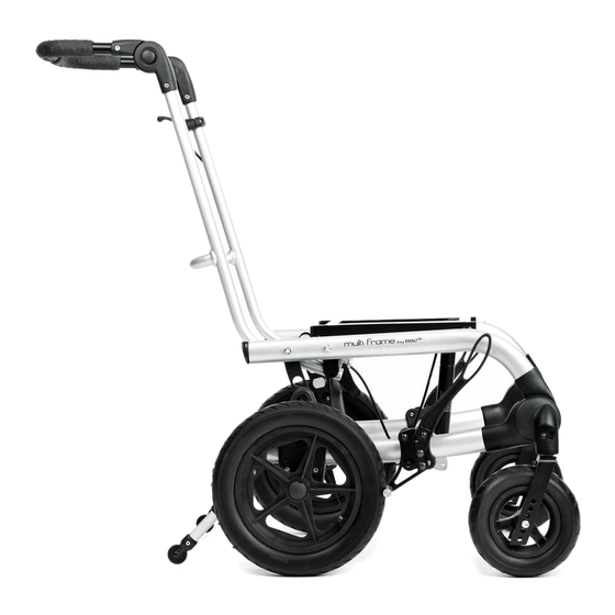
MULTI FRAME Congratulations on choosing the Multi Frame as your new wheelchair base. It is a high quality R82 product and we are convinced that it will fully live up to your expectations. Multi Frame is a smart and simple wheelchair frame designed for children and teenagers. -
Page 4: Ready For Use
READY FOR USE Multi Frame is folded when delivered but is un- folded very easily: 1) Push in the buttons (A) in both sides of the handle and fold out the push brace 2) The frame is folded out by lifting the push brace. -
Page 5: Adjusting The Push Brace
ADJUSTING THE PUSH BRACE The push brace can be adjusted into four po- sitions to make a bigger distance between the push brace and seat. 1) The push brace is angled by twisting the strap (A) under the basic frame whilst pushing the push brace forward or backward. -
Page 6: Angle The Push Handle
ANGLE THE PUSH HANDLE The push handle on the Multi Frame can easily be adjusted for angle/height. 1) Push the buttons (A) in both sides and hold them in 2) Move the push handle up or down to obtain the desired position. 3) Release the the buttons (A) and the push handle will stay in the desired position. -
Page 7: Seat Height Adjustment
SEAT HEIGHT ADJUSTMENT When adjusting the seat height the frame has to be adjusted up or down by the fitting (A) and the gas spring. Using 12,5" back wheels, you can adjust the height in the 3 upper holes in the fitting (A). Please see (A). -
Page 8: Angling / Tilting The Basic Frame
ANGLING / TILTING THE BASIC FRAME The basic frame (A) can be adjusted for angle. The basic frame can be tilted backwards by operating the lever (B) and using the push brace to position the tilt in the required position, once the required position is reached the Lever (B) can be released. -
Page 9: Gas Spring Adjustment
GAS SPRING ADJUSTMENT Occasionally the gas spring may need to be ad- justed. The adjustment is only necessary when: - the gas spring releases itself slowly - the gas spring can not be released at all If the gas spring releases itself; loosen the nut (B) with a 17 mm wrench. -
Page 10: Centre Of Gravity
CENTRE OF GRAVITY The center of gravity for the Multi Frame can be adjusted by moving the placement of the basic frame and by changing the position of an interface. The basic frame can be placed in 3 positions: Changing the placement of the basic frame: 1) Dismount the fitting (A) below the basic frame by removing (from below) the 2 bolts with a 4 mm allen key. -
Page 11: Folding The Multi Frame
FOLDING THE MULTI FRAME The push brace on Multi Frame can be folded down and make the frame smaller. Folding down: 1) If mounted, dismount the seat 2) Push the buttons (B) on the hand brace and fold the band brace. 3) Pull or twist lightly on the strap (A) from be- hind under the basic frame. -
Page 12: Wheel Lock 12½" And 22" Wheel
WHEEL LOCK 12½" AND 22" WHEEL Wheel locks are mounted on the frame and can be operated by either user or helper. Activate the wheel lock: Push the handles (A) on both sides down, to lock the wheels. Deactivate the wheel lock: Pull the handles (A) on both sides up, to lock the wheels. -
Page 13: Quick Release Wheels
QUICK RELEASE WHEELS Quick Release axle pins on the rear wheels is a standard feature of the Multi Frame - This aids in quick and easy removal (A): Push the release mechanism in the middle of the wheel and pull to remove the wheel. -
Page 14: Hand Brake
HAND BRAKE The hand brake handles are installed on the push brake and are operated by the helper. * Squeeze the handle to activate the brake. * Pull the red handle at the same time releasing the main handle (A) to disengage the brake. Adjustment of the hand brake: 12,5"... -
Page 15: Mounting Hand Brake On 22" Wheel
MOUNTING HAND BRAKE ON 22" WHEEL Follow these directions to mount a hand brake on 22" back wheels. 1) Remove the back wheel by using Quick release axle pin 2) Remove the Quick release bushing (A) with 2 24 mm spanners 3) Mount the drum brake with the enclosed nuts and washers in the order as shown (B). -
Page 16: Wheels
WHEELS Info about tyres recommended Tyre width Tyre type Extra air pressure 7" front wheel, black rubber 51 mm (2") 2,5 bar 12,5" back wheel, black rubber 60 mm (2¼") 2,5 bar 7" front wheel, black pur 30 mm (1¼") Solid Anti puncture 12,5"... -
Page 17: Interface For X: Panda And Panda Futura Seats
INTERFACE FOR X: PANDA AND PANDA FUTURA SEATS You can mount a special interface on the Multi Frame to mount an x:panda or a Panda Futura seat. 1. Place the interface in such way that you obtain the correct centre of gravity for the seat. 2. -
Page 18: Mounting A X:panda Or Panda Futura Seat In An Interface
MOUNTING A X:PANDA OR PANDA FUTURA SEAT IN AN INTERFACE Mount an x:panda or Panda Futura seat on Multi Frame: The seat is slid into in the adapter and should be pushed back until it "clicks". Then pull out the green knob and push the seat back until the green knob (A) clicks into the second safety hole. -
Page 19: Permanent Mounting Of X:panda Or Panda Futura Seat
PERMANENT MOUNTING OF X:PANDA OR PANDA FUTURA SEAT x:panda sz 3 and Panda Futura sz 5 can be permanent mounted on the Multi Frame. Use the enclosed 4 bolts, 4 washers and a 6 mm allen key (these comes with the Multi Frame). Place the seat on the frame. -
Page 20: Seat And Frame Sizes
SEAT AND FRAME SIZES Multi Frame Multi Frame Multi Frame Frame Seat sz 1 sz 2 sz 3 Panda Futura sz 1 ● ○ ○ Panda Futura sz 2 ● ○ ○ Panda Futura sz 2½ ● ○ Panda Futura sz 3 ●... -
Page 21: Foot Support
FOOT SUPPORT Mounting: Loosen the screws (B) with a 5 mm allen key and the foot support is mounted by placing the bars in the interface (A). Then refasten the screws (B). When mounting or adjusting the foot sup- port, be careful not to squeeze fingers! Adjustment: To angle the foot rest bar, loosen the grip (A). -
Page 22: Individual Foot Supports
INDIVIDUAL FOOT SUPPORTS Mounting: Loosen the screws (B) with a 5 mm allen key and the foot support is mounted by placing the bars in the interface (A). Then refasten the screws (B). Adjustment of individual foot supports 1: Angle adjustment - foot support bar: Loosen the handle (A). -
Page 23: Individual Footsupports For X:panda
INDIVIDUAL FOOTSUPPORTS FOR X:PANDA Mounting: Loosen the screws (B) with a 5 mm allen key and the foot support is mounted by placing the bars in the interface (A). Then refasten the screws (B). Width adjustment: Remove the screws (C) using the 5 mm Allen key. -
Page 24: Spoke Protectors
SPOKE PROTECTORS Follow the description below to mount spoke protectors on the Multi Frame: * Place the protector on the spokes * Mount the enclosed clips (A) through the holes in the spoke protectors and click into place on the spokes. -
Page 25: Vent Tray For Ventilator
VENT TRAY FOR VENTILATOR The vent tray can only be mounted on Multi Frame sizes 2 and 3. * Place the vent tray on the bottom bar on the frame (A). * Drill a 5 mm hole on each side of the frame and mount the straps with the enclosed bolts (B). -
Page 26: Declaration Of Conformity
If there is any doubt as to the continued safe use of your This product conforms to the requirements of the Medical R82 product or if any parts should fail, stop using the Devices Directive (93/42/EEC). The CE mark must be re-... -
Page 27: Service Information
Accessories and spare parts Daily The products from R82 can be supplied with a variety of • Use a dry cloth to clean the product accessories which comply with the needs of the individual •... -
Page 28: Symbols
Symbols For indoor and outdoor use Consult instructions The latest version of the instructions is always available on the R82 web- site and can be printed in larger sizes Warning This symbol appears in the User Guide along with a number referring to the instructions below. -
Page 29: Measurements
13 kg (28,6 lb) 13 kg (28,6 lb) 13 kg (28,6 lb) Total mass (22” air wheels+air front wheels) 14 kg (30,8 lb) 14 kg (30,8 lb) 14 kg (30,8 lb) Further information regarding max. load/user weight and transportation: www.support.r82.org... -
Page 30: Make The Multi Frame Ready For Transport
MAKE THE MULTI FRAME READY FOR TRANSPORT Transport fittings: * Mount two transport fittings (A) on both sides of the Frame * Mount two fittings (B) on the back of the frame. The transport fittings (A+B) are equipped with a secure symbol (C). -
Page 31: Product Identification
The label is placed to the far left on the front cross bar beneath the seat. C) Consult instructions The latest version of the instructions is always available on the R82 website and can be printed in larger sizes TECHNICAL DATA Frame:...
Need help?
Do you have a question about the multi frame Series and is the answer not in the manual?
Questions and answers