
Related Manuals for Fronius Robacta PTW 500


Summary of Contents for Fronius Robacta PTW 500
- Page 1 Operating instructions Robacta PTW 500, 1500, 3500 Bedienungsanleitung Operating instructions Instructions de service Instrukcja obsługi 操作说明书 42,0410,1151 010-12042022...
-
Page 3: Table Of Contents
Lieferumfang - Robacta PTW 1500 Lieferumfang - Robacta PTW 3500 Optionen PTW 500 Optionen PTW 1500 Optionen PTW 3500 Robacta PTW 500, 1500, 3500 montieren Sicherheit Robacta PTW 500 montieren Robacta PTW 1500 montieren Robacta PTW 3500 montieren Wolframelektrode einstellen... -
Page 4: Allgemeines
Schleppgasdüse ausgestattet werden. (Kalt-)-Drahtzuführung Robacta Plasma KD Drive Robacta PTW 500 Robacta PTW 500 mit den Optionen Robacta Plasma KD Drive und Drahtzuführung (Kalt-)-Drahtzuführung Robacta Plasma KD Drive Robacta PTW 1500 Robacta PTW 1500 mit den Optionen Robacta Plasma KD Drive und Drahtzuführung... -
Page 5: Einsatzgebiete
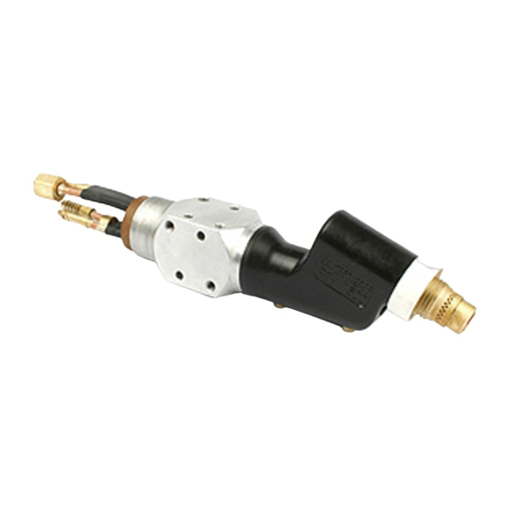
Qualitätsanforderungen bei Sonderwerkstoffen (z.B.: Titan, Nickelbasis-Legierungen) Lieferumfang - (10) Robacta PTW (10) (11) Schutz-Gasdüse Brennerkappe Plasmadüse 1,2 mm Schlauchpaket 4 m, Fronius F Keramik-Gasdüse ++ / FG Anschluss Brennerkörper mit Anschlag- Einstell-Lehre ring (10) Halterung Wolframelektrode 1,0 mm (11) Anschluss für Abschaltbox... -
Page 6: Lieferumfang - Robacta Ptw 1500
Lieferumfang - Robacta PTW (10) 1500 (11) Schutz-Gasdüse Brennerkappe Robacta PTW Plasmadüse 2,5 mm 1500 Keramik-Zentrierohr Schlauchpaket 4 m, Fronius F Brennerkörper mit Anschlag- ++ Anschluss ring Einstell-Lehre 2,5 - 3 mm Wolframelektrode WL15, 2,4 (10) Halterung (11) Anschluss für Abschaltbox Spannhülse 2,4 mm... -
Page 7: Optionen Ptw
Optionen PTW Option Heißdraht Plasmadüse 0,6 / 0,8 / 1,0 / 1,4 / 1,6 mm Adapter für das nicht digitale PlasmaModul Kaltdrahtzuführung mit Antrieb (Push-Pull-System): Robacta Plasma KD Drive Kaltdrahtzuführung (Push-System): Robacta Plasma KD Schleppgasdüse 50 / 100 mm Optionen PTW Einstell-Lehre ∅... -
Page 8: Robacta Ptw 500, 1500, 3500 Montieren
Robacta PTW 500, 1500, 3500 montieren Sicherheit WARNUNG! Gefahr durch Fehlbedienung und fehlerhaft durchgeführte Arbeiten. Schwere Personen- und Sachschäden können die Folge sein. ▶ Alle in diesem Dokument beschriebenen Arbeiten und Funktionen dürfen nur von technisch geschultem Fachpersonal ausgeführt werden. -
Page 9: Robacta Ptw 1500 Montieren
Robacta PTW 1500 montieren Halterung montieren, Spannhülse einsetzen Wolframelektrode einsetzen WICHTIG! Die Wolframelektrode so einsetzen, dass die Spitze ca. 10 mm aus dem Brennerkörper ragt. Brennerkappe leicht anziehen, die Wolframelektrode sollte im Brennerkörper noch verschiebbar sein. WICHTIG! Auf korrekte Einstellung der Wolframelektrode achten (siehe Kapitel „Wolframelektrode einstellen“) max. -
Page 10: Robacta Ptw 3500 Montieren
Robacta PTW 3500 montieren Wolframelektrode einsetzen Halterung montieren, Spannhülse einsetzen WICHTIG! Die Wolframelektrode so einsetzen, dass die Spitze ca. 10 mm aus dem Brennerkörper ragt. Brennerkappe leicht anziehen, die Wolframelektrode sollte im Brennerkörper noch verschiebbar sein. Wassergekühlte Schutz-Gasdüsen müssen an den Wasseranschlüssen an- geschlossen werden. -
Page 11: Wolframelektrode Einstellen
Wolframelektrode einstellen Sicherheit WARNUNG! Gefahr durch Fehlbedienung und fehlerhaft durchgeführte Arbeiten. Schwere Personen- und Sachschäden können die Folge sein. ▶ Alle in diesem Dokument beschriebenen Arbeiten und Funktionen dürfen nur von technisch geschultem Fachpersonal ausgeführt werden. ▶ Dieses Dokument vollständig lesen und verstehen. ▶... -
Page 12: Einstell-Lehre Ptw 1500 Justieren
... und Wolframelektrode einrichten Einstell-Lehre WICHTIG! Die Standard-Einstellung PTW 1500 jus- für das Maß „x“ an der jeweiligen Ein- tieren stell-Lehre ist abhängig vom Durch- messer der Plasmadüse. Standard-Ein- stellung für das Maß „x“ gemäß folgen- der Tabelle einstellen: ∅ Plasma- „x“... -
Page 13: Wolframelektrode Einstellen - Ptw 1500
Wolframelektro- de einstellen - PTW 1500 *) Brennerkappe lockern - je nach Brennerstel- Einstell-Lehre an der Plasmadüse ansetzen ... lung darauf achten, dass die Wolframelektrode nicht aus dem Plasmabrenner fällt! max. 3 Nm ... und Wolframelektrode einrichten Wolframelektrode mittels Brennerkappe fixieren Wolframelektro- de einstellen - PTW 3500... - Page 14 ... und Wolframelektrode einrichten Wolframelektrode mittels Brennerkappe fixieren...
-
Page 15: Inbetriebnahme
Inbetriebnahme Sicherheit WARNUNG! Gefahr durch Fehlbedienung und fehlerhaft durchgeführte Arbeiten. Schwere Personen- und Sachschäden können die Folge sein. ▶ Alle in diesem Dokument beschriebenen Arbeiten und Funktionen dürfen nur von technisch geschultem Fachpersonal ausgeführt werden. ▶ Dieses Dokument vollständig lesen und verstehen. ▶... - Page 16 Anschluss Pilotstrom Plus Anschluss Pilotstrom Minus / Plasmagas Anschlüsse Abschalt-Box Anschluss Wasserrücklauf Anschluss Wasserrvorlauf Anschluss Strom / Schutzgas Plasmabrenner-Schlauchpaket: Anschlüsse Bei Erstinbetriebnahme auf korrekte Gasströmung achten Plasmabrenner positionieren (Roboter einrichten) Schutzgas und Plasmagas für mindestens 30 sec. spülen HINWEIS! Der Plasmabrenner muss während des Betriebes ständig gekühlt werden. Kühlkreislauf der Plasma-Anlage auf richtige Funktion überprüfen, Kühlgerät auf Dauerbetrieb einstellen (z.B.: SetUp-Menü...
-
Page 17: Belastungsgrenzen In Abhängigkeit Von Der Plasmagas-Menge
Belastungsgrenzen in Abhängigkeit von der Plas- magas-Menge Allgemeines Belastungsgrenzen beim Plasmaschweißen / Plasmalöten hängen von folgenden Faktoren ab: Durchmesser der Plasmadüse Position der Wolframelektrode Plasmagas-Menge Die folgenden Belastungsgrenzen gelten bei Standard-Einstellung der Wolfram- elektrode (siehe auch Abschnitt „Wolframelektrode einstellen“). Belastungsgren- Zum Plasmaschweißen müssen die eingestellten Werte für Plasmagas-Menge zen in Abhängig- und maximalen Schweißstrom innerhalb der angegebenen Grenzwerte liegen. -
Page 18: Beispiel Belastungsgrenze - Ptw 1500
Tabelle gilt nur für PTW 3500 in Verbindung mit einem FK 9000 Kühlgerät ø Plasmadüse Plasmagas-Menge max. Schweißstrom 2,0 mm min. 1,0 l/min 170 A 2,5 mm min. 1,0 l/min 190 A 3,2 mm min. 1,0 l/min 210 A 3,5 mm min. -
Page 19: Fehlerdiagnose, Fehlerbehebung
Fehlerdiagnose, Fehlerbehebung Sicherheit WARNUNG! Ein elektrischer Schlag kann tödlich sein. Vor Arbeiten am Schweißbrenner: ▶ Netzschalter von Stromquelle und Plasmagerät in Stellung „0“ schalten ▶ Stromquelle und Plasmagerät vom Netz trennen ▶ ein verständliches Warnschild gegen Wiedereinschalten anbringen Fehlerdiagnose, Pilot-Lichtbogen zündet nicht Fehlerbehebung Ursache: Wolframelektrode fehlt... -
Page 20: Pflege, Wartung Und Entsorgung
Pflege, Wartung und Entsorgung Sicherheit WARNUNG! Ein elektrischer Schlag kann tödlich sein. Vor Arbeiten am Schweißbrenner: ▶ Netzschalter von Stromquelle und Plasmagerät in Stellung „0“ schalten ▶ Stromquelle und Plasmagerät vom Netz trennen ▶ ein verständliches Warnschild gegen Wiedereinschalten anbringen Allgemeines Regelmäßige und vorbeugende Wartung des Schweißbrenners sind wesentliche Faktoren für einen störungsfreien Betrieb. -
Page 21: Technische Daten
Kühlmitteldruck min. 3,0 bar 43,50 psi. Kühlmitteldruck max. 5,5 bar 79,74 psi. Kühlmittel-Mindestdurchfluss 1,0 l / min ED = Einschaltdauer *) Flüssigkeitskühlung **) Original Fronius-Kühlmittel ***) Geringste Kühlleistung laut Norm IEC 60974-2 Das Produkt entspricht den Anforderungen laut Norm IEC 60974-7... -
Page 22: Ptw 1500, Ptw 3500
5,5 bar 5,5 bar 79,74 psi. 79,74 psi. Kühlmittel-Mindestdurchfluss 1,0 l / min 1,0 l / min ED = Einschaltdauer *) Flüssigkeitskühlung **) Original Fronius-Kühlmittel ***) Geringste Kühlleistung laut Norm IEC 60974-2 Das Produkt entspricht den Anforderungen laut Norm IEC 60974-7... - Page 23 Contents General Machine concept Applications Scope of supply - Robacta PTW 500 Scope of supply - Robacta PTW 1500 Scope of supply - Robacta PTW 3500 PTW 500 options PTW 1500 options PTW 3500 options Assembling the Robacta PTW 500, 1500, 3500...
-
Page 24: General
(Cold) wire feeder Robacta Plasma KD Drive Robacta PTW 500 Robacta PTW 500 with Robacta Plasma KD Drive and wirefeed options Robacta PTW (Cold) wire feeder Robacta Plasma KD Drive Robacta PTW 1500 Robacta PTW 1500 with Robacta Plasma KD Drive and wirefeed options... -
Page 25: Applications
Scope of supply (10) - Robacta PTW (10) (11) Shielding gas nozzle Torch cap Plasma nozzle 1.2 mm Hosepack 4 m, Fronius F++ / Ceramic gas nozzle FG connection Torch body with stop ring Adjusting gauge Tungsten electrode 1.0 mm (10) Holder Clamping sleeve 1.0 mm... -
Page 26: Scope Of Supply - Robacta Ptw 1500
3500 (3) (4) (11) (12) Shielding gas nozzle Robacta PTW 3500 torch cap Plasma nozzle 3.2 mm Hosepack 4 m, Fronius F++ / Ceramic centring tube FG connection Torch body with stop ring Adjusting gauge Tungsten electrode WL 15, (10) Connection for cut-out box 4.8 mm... -
Page 27: Ptw 500 Options
PTW 500 opti- Hot wire option Plasma nozzle 0.6 / 0.8 / 1.0 / 1.4 / 1.6 mm Adapter for the non-digital PlasmaModul Cold wire feeder with drive (push-pull system): Robacta Plasma KD Drive Cold wire feeder (push system): Robacta Plasma KD Drag gas nozzle 50 / 100 mm PTW 1500 opti- Adjusting gauge ∅... -
Page 28: Assembling The Robacta Ptw 500, 1500, 3500
Assembling the Robacta PTW 500, 1500, 3500 Safety WARNING! Danger from incorrect operation and work that is not carried out properly. This can result in serious personal injury and damage to property. ▶ All the work and functions described in this document must only be carried out by technically trained and qualified personnel. -
Page 29: Assembling The Robacta Ptw 1500
Assembling the Robacta PTW 1500 Fit holder, insert clamping sleeve Insert tungsten electrode IMPORTANT! Insert the tungsten electrode so that the tip protrudes approx. 10 mm out of the torch body. Slightly tighten the torch cap so that the tungsten electrode can still move inside the torch body. -
Page 30: Assembling The Robacta Ptw 3500
Assembling the Robacta PTW 3500 Insert tungsten electrode Fit holder, insert clamping sleeve IMPORTANT! Insert the tungsten electrode so that the tip protrudes approx. 10 mm out of the torch body. Slightly tighten the torch cap so that the tungsten electrode can still move inside the torch body. -
Page 31: Adjusting The Tungsten Electrode
Adjusting the tungsten electrode Safety WARNING! Danger from incorrect operation and work that is not carried out properly. This can result in serious personal injury and damage to property. ▶ All the work and functions described in this document must only be carried out by technically trained and qualified personnel. -
Page 32: Calibrating The Ptw 1500 Adjusting Gauge
... and adjust tungsten electrode Calibrating the IMPORTANT! The standard setting for PTW 1500 adjus- measurement „x“ on the adjusting gau- ting gauge ge depends on the diameter of the plasma nozzle. Refer to the following table when adjusting the standard set- ting for measurement „x“: ∅... -
Page 33: Adjusting The Ptw 1500 Tungsten Electrode
Adjusting the PTW 1500 tungsten elec- trode Loosen the torch cap - caution, the tungsten Place adjusting gauge onto plasma nozzle ... electrode may fall out of the plasma torch if the torch is in a particular position. max. 3 Nm ... - Page 34 ... and adjust tungsten electrode Fix the tungsten electrode in place using the torch cap...
-
Page 35: Start-Up
Start-up Safety WARNING! Danger from incorrect operation and work that is not carried out properly. This can result in serious personal injury and damage to property. ▶ All the work and functions described in this document must only be carried out by technically trained and qualified personnel. - Page 36 Pilot flow plus connection Pilot flow minus / plasma gas connection Cut-out box connections Water return connection Water flow connection Current/shielding gas connection Plasma torch hosepack: connections When starting up for the first time, make sure the gas flow is correct Position plasma torch (adjust robot) Purge shielding gas and plasma gas for at least 30 seconds NOTE!
-
Page 37: Loading Limits Dependent On The Plasma Gas Flow Rate
Loading limits dependent on the plasma gas flow rate General Loading limits for plasma welding/plasma brazing depend on the following fac- tors: Diameter of the plasma nozzle Position of the tungsten electrode Plasma gas flow rate The following loading limits apply to the standard tungsten electrode setting (see also „Adjusting the tungsten electrode“). -
Page 38: Loading Limit Example (Ptw 1500)
This table is only valid for the PTW 3500 in conjunction with a FK9000 cooling unit: ø Plasma nozzle Plasma gas flow rate Max. welding current 2.0 mm Min. 1.0 l/min 170 A 2.5 mm Min. 1.0 l/min 190 A 3.2 mm Min. -
Page 39: Troubleshooting
Troubleshooting Safety WARNING! An electric shock can be fatal. Before carrying out any work on the welding torch: ▶ Turn the mains switches of the power source and plasma device to the "0" position ▶ Disconnect the power source and plasma device from the mains ▶... -
Page 40: Care, Maintenance And Disposal
Care, maintenance and disposal Safety WARNING! An electric shock can be fatal. Before carrying out any work on the welding torch: ▶ Turn the mains switches of the power source and plasma device to the "0" position ▶ Disconnect the power source and plasma device from the mains ▶... - Page 41 Separate collection according to material. Check your local authority regulations. Crush containers to reduce size.
-
Page 42: Technical Data
Max. coolant pressure 5.5 bar 79.74 psi. Minimum coolant flowrate 1.0 l/min d.c. = duty cycle *) Liquid cooling **) Original Fronius coolant ***) Minimum cooling power in accordance with standard IEC 60974-2 The product complies with standard IEC 60974-7... -
Page 43: Ptw 1500, Ptw 3500
5.5 bar 79.74 psi. 79.74 psi. Minimum coolant flowrate 1.0 l/min 1.0 l/min d.c. = duty cycle *) Liquid cooling **) Original Fronius coolant ***) Minimum cooling power in accordance with standard IEC 60974-2 The product complies with standard IEC 60974-7... - Page 45 Livraison - Robacta PTW 1500 Livraison - Robacta PTW 3500 Options PTW 500 Options PTW 1500 Options PTW 3500 Montage Robacta PTW 500, 1500, 3500 Sécurité Montage Robacta PTW 500 Montage Robacta PTW 1500 Montage Robacta PTW 3500 Régler l'électrode tungstène Sécurité...
-
Page 46: Généralités
à gaz de traînage. Guide-fil (froid) Robacta Plasma KD Drive Robacta PTW 500 Robacta PTW 500 avec les options Robacta Plasma KD Drive et guide-fil Guide-fil (froid) Robacta Plasma KD Drive Robacta PTW 1500 Robacta PTW 1500 avec les options Robacta Plasma KD Drive et guide-fil... -
Page 47: Domaines D'application
(11) Buse gaz de protection Cache de torche Buse plasma 1,2 mm Faisceau de liaison 4 m, Rac- Buse gaz céramique cord Fronius F++ / FG Corps de torche avec bague Gabarit de réglage de butée (10) Support Électrode tungstène 1,0 mm (11) Raccord pour boîtier de... -
Page 48: Livraison - Robacta Ptw 1500
Cache de torche Robacta Buse plasma 2,5 mm PTW 1500 Tube de centrage céramique Faisceau de liaison 4 m, Rac- Corps de torche avec bague cord Fronius F++ de butée Gabarit de réglage 2,5 - 3 mm Électrode tungstène WL 15, (10) Support... -
Page 49: Options Ptw 3500
Buse plasma 3,2 mm PTW 3500 Tube de centrage céramique Faisceau de liaison 4 m, Rac- Corps de torche avec bague cord Fronius F++ / FG de butée Gabarit de réglage Électrode tungstène WL 15, (10) Raccord pour boîtier de 4,8 mm déconnexion... -
Page 50: Montage Robacta Ptw 500, 1500, 3500
Montage Robacta PTW 500, 1500, 3500 Sécurité AVERTISSEMENT! Danger dû à une erreur de manipulation et d'erreur en cours d'opération. Cela peut entraîner des dommages corporels et matériels graves. ▶ Toutes les fonctions et tous les travaux décrits dans le présent document doivent uniquement être exécutés par du personnel techniquement qualifié. -
Page 51: Montage Robacta Ptw 1500
Montage Robac- ta PTW 1500 Montage du support, mise en place de la douille Mise en place de l’électrode en tungstène de serrage IMPORTANT! Insérer l’électrode de tungstène de manière à ce que la pointe dépasse d’env. 10 mm hors du corps de la torche. Tirer légèrement le cache de torche, l’électrode en tungstène doit encore pouvoir coulisser dans le corps de torche. -
Page 52: Montage Robacta Ptw 3500
Montage Robac- ta PTW 3500 Mise en place de l’électrode en tungstène Montage du support, mise en place de la douille de serrage IMPORTANT! Insérer l’électrode de tungstène de manière à ce que la pointe dépasse d’env. 10 mm hors du corps de la torche. Tirer légèrement le cache de torche, l’électrode en tungstène doit encore pouvoir coulisser dans le corps de torche. -
Page 53: Régler L'électrode Tungstène
Régler l'électrode tungstène Sécurité AVERTISSEMENT! Danger dû à une erreur de manipulation et d'erreur en cours d'opération. Cela peut entraîner des dommages corporels et matériels graves. ▶ Toutes les fonctions et tous les travaux décrits dans le présent document doivent uniquement être exécutés par du personnel techniquement qualifié. ▶... -
Page 54: Ajuster Le Gabarit De Réglage Ptw 1500
... et régler l’électrode en tungstène Ajuster le gaba- IMPORTANT! Le réglage de base pour rit de réglage la mesure « X » sur le gabarit de régla- PTW 1500 ge correspondant est fonction du diamètre de la buse plasma. Ajuster le réglage de base pour la mesure «... -
Page 55: Régler L'électrode En Tungstène Ptw 1500
Régler l’électro- de en tungstène PTW 1500 Desserrer la cache de torche - en fonction de la Mettre en place le gabarit de réglage sur la buse position de la torche, veiller à ce que l’électrode plasma ... ne tombe pas de la torche plasma ! max. - Page 56 ... et régler l’électrode en tungstène Fixer l’électrode en tungstène à l’aide du cache de torche...
-
Page 57: Mise En Service
Mise en service Sécurité AVERTISSEMENT! Danger dû à une erreur de manipulation et d'erreur en cours d'opération. Cela peut entraîner des dommages corporels et matériels graves. ▶ Toutes les fonctions et tous les travaux décrits dans le présent document doivent uniquement être exécutés par du personnel techniquement qualifié. ▶... - Page 58 Raccord arc pilote Plus Raccord arc pilote Moins / plasma de gaz Raccords boîtier de déconnexion Raccord retour d’eau Raccord arrivée d’eau Raccord courant / gaz de protection Faisceau de liaison torche plasma : Raccords Lors de la première mise en service, veiller au bon débit du gaz Positionner la torche plasma (mettre en place le robot) Rincer au gaz de protection et au plasma de gaz pendant au moins 30 sec REMARQUE!
-
Page 59: Limites De Charge En Fonction De La Quantité De Plasma De Gaz
Limites de charge en fonction de la quantité de plasma de gaz Généralités Les limites de charge lors du soudage à l’arc plasma / du brasage plasma dépen- dent des facteurs suivants : diamètre de la buse plasma position de l’électrode en tungstène quantité... -
Page 60: Exemple De Limite De Charge (Ptw 1500)
Tableau uniquement valable pour PTW 3500 en combinaison avec un refroidis- seur FK9000 : ø Buse plasma Quantité de plasma de gaz Intensité de soudage max. 2,0 mm min. 1,0 l/min 170 A 2,5 mm min. 1,0 l/min 190 A 3,2 mm min. -
Page 61: Diagnostic D'erreur, Élimination De L'erreur
Diagnostic d’erreur, élimination de l'erreur Sécurité AVERTISSEMENT! Une décharge électrique peut être mortelle. Avant tous travaux sur la torche de soudage : ▶ mettre l'interrupteur d'alimentation de la source de courant et de l'appareil plasma sur « 0 » ▶ déconnecter la source de courant et l'appareil plasma du réseau ▶... -
Page 62: Maintenance, Entretien Et Élimination
Maintenance, entretien et élimination Sécurité AVERTISSEMENT! Une décharge électrique peut être mortelle. Avant tous travaux sur la torche de soudage : ▶ mettre l'interrupteur d'alimentation de la source de courant et de l'appareil plasma sur « 0 » ▶ déconnecter la source de courant et l'appareil plasma du réseau ▶... - Page 63 Matériaux d’emballage Collecte sélective. Vérifiez la réglementation de votre commune. Réduisez le vo- lume du carton.
-
Page 64: Caractéristiques Techniques
Débit minimal de réfrigérant 1,0 l/min f.m. = facteur de marche *) Refroidissement par liquide **) Réfrigérant d’origine Fronius ***) Puissance de refroidissement minimale conformént à la norme IEC 60974-2 Ce produit satisfait aux exigences de la norme IEC 60974-7... -
Page 65: Ptw 1500, Ptw 3500
Débit minimal de réfrigérant 1,0 l/min 1,0 l/min f.m. = facteur de marche *) Refroidissement par liquide **) Réfrigérant d’origine Fronius ***) Puissance de refroidissement minimale conformént à la norme IEC 60974-2 Ce produit satisfait aux exigences de la norme IEC 60974-7... - Page 67 Spis treści Informacje ogólne Koncepcja urządzenia Obszary zastosowań Zakres dostawy - Robacta PTW 500 Zakres dostawy - Robacta PTW 1500 Zakres dostawy - Robacta PTW 3500 Opcje PTW 500 Opcje PTW 1500 Opcje PTW 3500 Montaż Robacta PTW 500, 1500, 3500 Bezpieczeństwo...
-
Page 68: Informacje Ogólne
Doprowadzenie drutu (zimnego) Robacta Plasma KD Drive Robacta PTW 500 Robacta PTW 500 z opcjami Robacta Plasma KD Drive i doprowadzaniem drutu Doprowadzenie drutu (zimnego) Robacta Plasma KD Drive Robacta PTW 1500 Robacta PTW 1500 z opcjami Robacta Plasma KD Drive i doprowadzaniem drutu... -
Page 69: Obszary Zastosowań
Dysza gazu ochronnego Kapturek palnika spawalnic- Dysza plazmowa 1,2 mm zego Ceramiczna dysza gazowa Wiązka uchwytu 4 m, Korpus palnika spawalniczego Przyłącze Fronius F++ / FG z pierścieniem mocującym Sprawdzian nastawczy Elektroda wolframowa 1,0 (10) Uchwyt (11) Przyłącze do skrzynki Nakrętka mocująca 1,0 mm... -
Page 70: Zakres Dostawy - Robacta Ptw
Kapturek palnika spawalnic- Dysza plazmowa 2,5 mm zego Robacta PTW 1500 Ceramiczna rurka centrująca Wiązka uchwytu 4 m, Korpus palnika spawalniczego Przyłącze Fronius F++ z pierścieniem mocującym Sprawdzian nastawczy 2,5 - 3 Elektroda wolframowa WL 15, 2,4 mm (10) Uchwyt Nakrętka mocująca 2,4 mm... - Page 71 Kapturek palnika spawalnic- Dysza plazmowa 3,2 mm zego Robacta PTW 3500 Ceramiczna rurka centrująca Wiązka uchwytu 4 m, Korpus palnika spawalniczego Przyłącze Fronius F++ / FG z pierścieniem mocującym Sprawdzian nastawczy Elektroda wolframowa WL 15, (10) Przyłącze do skrzynki 4,8 mm odłączającej...
-
Page 72: Montaż Robacta Ptw 500, 1500, 3500
Montaż Robacta PTW 500, 1500, 3500 Bezpieczeństwo NIEBEZPIECZEŃSTWO! Niebezpieczeństwo wskutek błędów obsługi i nieprawidłowego wykonywania prac. Skutkiem mogą być poważne uszczerbki na zdrowiu i straty materialne. ▶ Wszystkie prace i funkcje opisane w tym dokumencie mogą wykonywać tylko technicznie przeszkoleni pracownicy. -
Page 73: Montaż Robacta Ptw 1500
WAŻNE! Należy zwracać uwagę na właściwe ustawienie elektrody wolf- ramowej (patrz rozdział „Ustawianie elektrody wolframowej“) Montaż rurki centrującej, dyszy plazmowej i dys- zy gazu ochronnego Montaż Robacta PTW 1500 Montaż uchwytu, wkładanie nakrętki mocującej Wkładanie elektrody wolframowej WAŻNE! Elektrodę wolframową należy włożyć w taki sposób, aby jej czubek wystawał... -
Page 74: Montaż Robacta Ptw 3500
WAŻNE! Należy zwracać uwagę na właściwe ustawienie elektrody wolf- ramowej (patrz rozdział „Ustawianie elektrody wolframowej“) max. 3 Nm Montaż rurki centrującej, dyszy plazmowej i dys- zy gazu ochronnego Montaż Robacta PTW 3500 Wkładanie elektrody wolframowej Montaż uchwytu, wkładanie nakrętki mocującej WAŻNE! Elektrodę... - Page 75 Chłodzone wodą dysze gazu ochronne- go należy podłączyć do przyłączy wody. Ceramiczne dysze gazu ochronnego nie wymagają chłodzenia wodą. W przypadku zastosowania ceramicznych dysz gazu ochronnego, oba przyłącza wody należy połączyć za pomocą pałąka wodnego. WAŻNE! Należy zwracać uwagę na właściwe ustawienie elektrody wolf- ramowej (patrz rozdział...
-
Page 76: Ustawianie Elektrody Wolframowej
Ustawianie elektrody wolframowej Bezpieczeństwo NIEBEZPIECZEŃSTWO! Niebezpieczeństwo wskutek błędów obsługi i nieprawidłowego wykonywania prac. Skutkiem mogą być poważne uszczerbki na zdrowiu i straty materialne. ▶ Wszystkie prace i funkcje opisane w tym dokumencie mogą wykonywać tylko technicznie przeszkoleni pracownicy. ▶ Przeczytać i zrozumieć cały niniejszy dokument. ▶... -
Page 77: Wzorcowanie Sprawdzianu Nastawczego Ptw 1500
... i ustawienie elektrody Wzorcowanie WAŻNE! Standardowe ustawienie na sprawdzianu wymiar „x“ w przypadku danego nastawczego sprawdzianu nastawczego jest uza- PTW 1500 leżnione od średnicy dyszy plazmowej. Standardowe ustawienie na wymiar „x“ należy ustawić korzystając z poniższej tabeli: ∅ Dysza „x“... -
Page 78: Ustawianie Elektrody Wolframowej Ptw 1500
Ustawianie elek- trody wolframo- wej PTW 1500 Poluzować kapturek palnika - w zależności od Przyłożyć sprawdzian nastawczy do dyszy ustawienia palnika zwracać uwagę, aby elektro- plazmowej ... da wolframowa nie wypadła z plazmowego pal- nika spawalniczego! max. 3 Nm ... i ustawienie elektrody Zamocować... -
Page 79: Ustawianie Elektrody Wolframowej Ptw 3500
Ustawianie elek- trody wolframo- wej PTW 3500 Poluzować kapturek palnika - w zależności od Przyłożyć sprawdzian nastawczy do dyszy ustawienia palnika zwracać uwagę, aby elektro- plazmowej ... da wolframowa nie wypadła z plazmowego pal- nika spawalniczego! ... i ustawienie elektrody Zamocować... -
Page 80: Uruchamianie
Uruchamianie Bezpieczeństwo NIEBEZPIECZEŃSTWO! Niebezpieczeństwo wskutek błędów obsługi i nieprawidłowego wykonywania prac. Skutkiem mogą być poważne uszczerbki na zdrowiu i straty materialne. ▶ Wszystkie prace i funkcje opisane w tym dokumencie mogą wykonywać tylko technicznie przeszkoleni pracownicy. ▶ Przeczytać i zrozumieć cały niniejszy dokument. ▶... - Page 81 Przyłącze prądu pilotującego, biegun dodatni Przyłącze prądu pilotującego, biegun ujemny / gaz plazmotwórczy Przyłącza skrzynki odłączającej Przyłącze dopływu wody Przyłącze zasilania wodą Przyłącze prądu / gazu ochronnego Wiązka uchwytu plazmowego palnika spawalniczego: przyłącza Przy pierwszym uruchomieniu należy zwracać uwagę na prawidłowy przepływ gazu Nadać...
-
Page 82: Granice Obciążenia W Zależności Od Ilości Gazu Plazmotwórczego
Granice obciążenia w zależności od ilości gazu plazmotwórczego Informacje Granice obciążenia przy spawaniu / lutowaniu plazmowym zależą od ogólne następujących czynników: średnicy dyszy plazmowej pozycji elektrody wolframowej ilości gazu plazmotwórczego Poniżej podane granice obciążeń obowiązują przy standardowym ustawieniu elek- trody wolframowej (patrz także ustęp „Ustawianie elektrody wolframowej“). Granice ob- Podczas spawania plazmowego, wartości ustawione dla gazu plazmotwórczego ciążenia w za-... -
Page 83: Przykład Granicy Obciążenia (Ptw 1500)
ø plazmowego palnika Ilość gazu maks. prąd spawania spawalniczego plazmotwórczego 3,0 mm min. 0,55 l/min 130 A maks. 1,30 l/min 150 A Tabela dotyczy tylko PTW 3500 w połączeniu z chłodnicą FK9000: ø plazmowego palnika Ilość gazu maks. prąd spawania spawalniczego plazmotwórczego 2,0 mm... -
Page 84: Lokalizacja I Usuwanie Usterek
Lokalizacja i usuwanie usterek Bezpieczeństwo NIEBEZPIECZEŃSTWO! Porażenie prądem elektrycznym może spowodować śmierć. Przed wykonaniem prac przy uchwycie spawalniczym: ▶ Wyłącznik źródła energii i urządzenia plazmowego ustawić w pozycji „0” ▶ Odłączyć źródło energii oraz urządzenie plazmowe od sieci ▶ Umieścić wyraźną tabliczkę ostrzegającą przed ponownym włączeniem Lokalizacja i usu- Łuk pilotujący nie zajarza się... -
Page 85: Bezpieczeństwo
Czyszczenie, konserwacja i utylizacja Bezpieczeństwo NIEBEZPIECZEŃSTWO! Porażenie prądem elektrycznym może spowodować śmierć. Przed wykonaniem prac przy uchwycie spawalniczym: ▶ Wyłącznik źródła energii i urządzenia plazmowego ustawić w pozycji „0” ▶ Odłączyć źródło energii oraz urządzenie plazmowe od sieci ▶ Umieścić wyraźną tabliczkę ostrzegającą przed ponownym włączeniem Informacje Regularna i profilaktyczna konserwacja palnika spawalniczego to istotny czynnik, ogólne... - Page 86 Materiały opakowaniowe Selektywna zbiórka odpadów. Proszę zapoznać się z przepisami obowiązującymi w Państwa gminie. Zgnieść karton przed wyrzuceniem, aby zmniejszyć jego objętość.
-
Page 87: Dane Techniczne
Maksymalne ciśnienie płynu chłodzącego 5,5 bar 79,74 psi. Minimalny przepływ płynu chłodzącego 1,0 l/min ED = Czas włączenia *) Chłodzenie cieczą **) Oryginalny płyn chłodzący Fronius ***) Najniższa wydajność chłodzenia wg normy IEC 60974-2 Produkt spełnia wymogi normy IEC 60974-7... -
Page 88: Ptw 1500, Ptw 3500
5,5 bar 79,74 psi. 79,74 psi. Minimalny przepływ płynu chłodzącego 1,0 l/min 1,0 l/min ED = Czas włączenia *) Chłodzenie cieczą **) Oryginalny płyn chłodzący Fronius ***) Najniższa wydajność chłodzenia wg normy IEC 60974-2 Produkt spełnia wymogi normy IEC 60974-7... - Page 89 目录 概述 机器设计方案 应用场合 供应范围 - Robacta PTW 500 供应范围 - Robacta PTW 1500 供应范围 - Robacta PTW 3500 PTW 500 选件 PTW 1500 选件 PTW 3500 选件 装配 Robacta PTW 500、1500、3500 安全 装配 Robacta PTW 500 装配 Robacta PTW 1500 装配...
- Page 90 水冷等离子机器人焊枪为等离子焊和高达 1.5 mm (PTW 500)、3 mm (PTW 1500) 和 8 mm (PTW 3500) 厚度的等离子焊和等离子钎焊材料所设计。 焊枪标配 Fronius F++ 接口。有各种适配器可供选择,使焊枪能够与任何标准等离子设备 一同操作。每个焊枪都可配备 KD Drive、推动式送丝机或拖动式气体喷嘴。 带 Robacta Plasma KD Drive 和送丝机选件 Robacta PTW 的 Robacta PTW 500 带 Robacta Plasma KD Drive 和送丝机选件的 Robacta PTW 1500...
- Page 91 带 Robacta Plasma KD Drive 和送丝机选件的 Robacta PTW 3500 应用场合 等离子机器人焊枪用于自动化应用场合,例如: 管线和设备建造 电池槽建造 需要最高质量标准的应用场合 使用特殊材料(例如,钛、镍基合金)的应用场合 供应范围 - Robacta PTW 500 (10) (10) (11) 保护气体喷嘴 焊枪盖帽 等离子喷嘴 1.2 mm 中继线 4 m,Fronius F++ / FG 陶瓷气体喷嘴 接口 带止动环的焊枪体 调整测量量具 钨极 1.0 mm (10) 支护 夹紧衬套 1.0 mm (11) 断流器盒接口...
-
Page 92: 应用场合 供应范围 - Robacta Ptw
夹紧衬套 2.4 mm 供应范围 - Robacta PTW (10) 3500 (3) (4) (11) (12) 保护气体喷嘴 Robacta PTW 3500 焊枪盖帽 等离子喷嘴 3.2 mm 中继线 4 m,Fronius F++ / FG 陶瓷定心管 接口 带止动环的焊枪体 调整测量量具 钨极 WL 15,4.8 mm (10) 断流器盒接口 夹紧衬套 4.8 mm (11) 防水塞... -
Page 93: Ptw 500 选件
PTW 500 选件 热线选件 等离子喷嘴 0.6 / 0.8 / 1.0 / 1.4 / 1.6 mm 非数字的 PlasmaModul 适配器 带驱动装置的冷焊丝送丝机(推拉系统): Robacta Plasma KD Drive 冷焊丝送丝机(推式系统): Robacta Plasma KD 拖动式气体喷嘴 50 / 100 mm PTW 1500 选件 调整测量量具 ∅ 1.5 - 2 mm 带驱动装置的冷焊丝送丝机(推拉系统):Robacta Plasma KD Drive 冷焊丝送丝机(推式系统):Robacta Plasma KD 热线选件... -
Page 94: 装配 Robacta Ptw 500、1500、3500
装配 Robacta PTW 500、1500、3500 安全 危险! 误操作和工作不当时存在危险。 此时可能导致严重的人身伤害和财产损失。 ▶ 仅接受过技术培训且有资质人员方可执行本文档中所述的全部操作和功能。 ▶ 完整阅读并充分理解本文档。 ▶ 阅读并理解本设备以及全部系统组件的所有安全规程和用户文档。 装配 Robacta PTW 2x360° 插入夹紧衬套 插入钨极 重要!插入钨极以使尖端从焊枪体突出大约 10 mm。稍微拧紧焊枪盖帽,使钨极仍可在 焊枪体内移动。 重要!检查钨极是否正确调整(参见“调整 钨极”。 装配定心管、等离子喷嘴和保护气体喷嘴... - Page 95 装配 Robacta PTW 1500 安装支护,插入夹紧衬套 插入钨极 重要!插入钨极以使尖端从焊枪体突出大约 10 mm。稍微拧紧焊枪盖帽,使钨极仍可在 焊枪体内移动。 重要!检查钨极是否正确调整(参见“调整 钨极”) max. 3 Nm 装配定心管、等离子喷嘴和保护气体喷嘴 装配 Robacta PTW 3500 插入钨极 安装支护,插入夹紧衬套...
- Page 96 重要!插入钨极以使尖端从焊枪体突出大约 10 mm。稍微拧紧焊枪盖帽,使钨极仍可在 焊枪体内移动。 水冷保护气体喷嘴必须连接到水接口。 陶瓷保护气体喷嘴不需要任何水冷却。如果 使用陶瓷保护气体喷嘴,必须使用防水塞将 两个水接口连在一起。 重要!检查钨极是否正确调整(参见“调整 钨极”) 装配定心管、等离子喷嘴和保护气体喷嘴...
- Page 97 调整钨极 安全 危险! 误操作和工作不当时存在危险。 此时可能导致严重的人身伤害和财产损失。 ▶ 仅接受过技术培训且有资质人员方可执行本文档中所述的全部操作和功能。 ▶ 完整阅读并充分理解本文档。 ▶ 阅读并理解本设备以及全部系统组件的所有安全规程和用户文档。 概要 除指定等离子气体流量外,钨极的位置在确定负载限制方面也起着至关重要的作用。 负载限制是指最大可能的焊接电流 对于特定等离子喷嘴, 对于特定等离子气体流速, 对于特定钨极位置。 用于等离子焊 / 等离子钎焊的钨极设置过程将在以下部分中有所描述。 调整 PTW 500 钨极 2x360° *) 松开焊枪盖帽 - 注意,如果焊枪处于特定位置,钨 极可能会从等离子焊枪中掉出。 … 调整钨极...
- Page 98 校准 PTW 1500 调 重要!在调整测量量具上测量值“x”的标 整测量量具 准设置取决于等离子喷嘴的直径。调整测量 值“x”的标准设置时,请参阅下表: ∅ 等离子 “x” 调整测量量具 喷嘴 1.0 mm 1.5 mm 1.5 mm ∅1.5 - 2 mm 2.0 mm 2.0 mm ∅1.5 - 2 mm 2.5 mm 2.5 mm ∅2.5 - 3 mm 3.0 mm 2.5 mm ∅2.5 - 3 mm 将调整测量量具设置为测量值“x”...
- Page 99 max. 3 Nm … 调整钨极 使用焊枪盖帽固定钨极就位 调整 PTW 3500 钨 极 松开焊枪盖帽 - 注意,如果焊枪处于特定位置,钨极 将调整测量量具放在等离子喷嘴上… 可能会从等离子焊枪中掉出。 … 调整钨极 使用焊枪盖帽固定钨极就位...
- Page 100 调试 安全 危险! 误操作和工作不当时存在危险。 此时可能导致严重的人身伤害和财产损失。 ▶ 仅接受过技术培训且有资质人员方可执行本文档中所述的全部操作和功能。 ▶ 完整阅读并充分理解本文档。 ▶ 阅读并理解本设备以及全部系统组件的所有安全规程和用户文档。 正确使用 等离子焊枪专门用于等离子焊和等离子钎焊。如果将设备用于其它任何用途,或以其它任 何方式使用该设备,都将被视为“不符合指定用途”。对于因此类不当使用所导致的任何 损失,制造商概不负责。 依照“指定用途”进行使用时还要 遵守本操作说明书中的所有操作说明 执行所有指定的检查和保养作业 启动 在机器人上安装等离子焊枪 检查等离子焊枪是否: 所有部件都存在 部件已正确安装 注意! 调试期间钨极调整不当可能会损坏等离子喷嘴。根据使用的等离子喷嘴和应用场合调整钨 极。 使用调整测量量具调整钨极 将等离子焊枪中继线的部件连接到等离子设备: 电流/保护气体接口 先导流量电缆 先导质量流量/等离子气体的电缆 回水软管 水流软管...
- Page 101 等离子焊枪中继线:接口 首次投入使用时,请确保气体流量正确 放置等离子焊枪(调整机器人) 吹扫保护气体和等离子气体至少 30 秒 注意! 等离子焊枪在操作过程中必须经常冷却。 检查等离子机器上的冷却电路是否正常运行,将冷却器设置为永久运行(例如焊接变 压器上的设置菜单,焊接参数 C-C =ON) 注意! 在未预设等离子气体的情况下点燃维弧会损坏等离子喷嘴、陶瓷定心管和钨极(所有易损 件)。 指定等离子气体值(根据等离子喷嘴的直径和应用场合) 点燃维弧 重要!要减少磨损,维弧应在整个操作过程中燃烧。 开始焊接(取决于应用场合)...
- Page 102 负载限制取决于等离子气体流速 概要 等离子焊/等离子钎焊的负载限制取决于以下因素: 等离子喷嘴的直径 钨极的位置 等离子气体流速 以下负载限制适用于标准钨极设置(另请参阅“调整钨极”)。 负载限制取决于等 对于等离子焊,等离子气体流速值和最大焊接电流必须在设置范围内。超出或低于这些范 离子气体流速 围可能会改变等离子属性,例如: 等离子气体流速低 -> “软”等离子体束 等离子气体流速高 -> “硬”等离子体束(“等离子切割”) 重要!操作过程中不要超出或低于等离子气体值和最大焊接电流的设置范围。 重要!最低冷却剂流速为 1 l/min 此表仅适用于 PTW 500(电极直径 1.0 mm;d.c.60%): ∅ 等离子喷嘴 等离子气体流速 最大焊接电流 0.6 mm 最低 0.30 l/min 15 A 0.8 mm 最低 0.30 l/min 20 A 1 mm 最低...
-
Page 103: 负载范围示例 (Ptw 1500)
∅ 等离子喷嘴 等离子气体流速 最大焊接电流 4.0 mm 最低 1.0 l/min 250 A 表仅适用于 PTW 3500 与 CHILLY 15 冷却器: ∅ 等离子喷嘴 等离子气体流速 最大焊接电流 2.0 mm 最低 1.0 l/min 225 A 2.5 mm 最低 1.0 l/min 250 A 3.2 mm 最低 1.0 l/min 275 A 3.5 mm 最低... - Page 104 错误诊断和错误排除 安全 危险! 电击可能致命。 在焊枪上执行任何操作之前: ▶ 将焊接变压器和等离子设备的电网开关转到零点 ▶ 从电网断开焊接变压器和等离子设备 ▶ 张贴易于理解的警告牌以防止任何人员不经意间再次接通电源 错误诊断和错误排 维弧未点燃 除 原因: 钨极缺失 解决方法: 插入钨极 原因: 等离子喷嘴和钨极相距太远 解决方法: 正确放置钨极 原因: 等离子喷嘴和钨极互相接触或过近(等离子喷嘴和钨极之间短路) 解决方法: 正确放置钨极 短时间焊接后等离子喷嘴上出现铜液滴 等离子喷嘴上形成液滴表明等离子喷嘴已严重损坏:等离子喷嘴因高温熔化并泄漏。 原因: 负载值过高 解决方法: 检查电流和等离子气体流速、更换等离子喷嘴、减少负载 等离子喷嘴过度磨损 原因: 冷却不充分 解决方法: 检查电流和等离子气体流速、检查冷却电路、提高等离子气体流速、检查喷 嘴接口上的磨损程度...
-
Page 105: 维护、保养和废料处理
维护、保养和废料处理 安全 危险! 电击可能致命。 在焊枪上执行任何操作之前: ▶ 将焊接变压器和等离子设备的电网开关转到零点 ▶ 从电网断开焊接变压器和等离子设备 ▶ 张贴易于理解的警告牌以防止任何人员不经意间再次接通电源 概述 定期地进行预防性维护对焊枪的无故障运行至关重要。焊枪暴露在高温下。因此与焊接设 备其他组件相比,焊枪需要更加频繁的维护。 每次启动时 检查等离子焊枪、焊枪中继线和电流接口是否存在损坏迹象 检查气体和水接口是否存在泄漏 检查用于冷却等离子焊枪的冷却器是否工作正常、监控冷却剂容器的回液位,必要时 为冷却器放液 检查等离子焊枪的易损件是否完好,安装前清洁易损件 检查连接头螺母是否牢固(中继线 - 等离子焊枪接口) 每月 如适用,检查冷却电路中的过滤器是否有污染 检查冷却剂是否纯净;如有任何杂质,请更换冷却剂并彻底冲洗等离子焊枪数次,让 冷却剂流入并再次流出 注意! 等离子焊枪内部的沉积物会导致高频电弧放电,从而损坏等离子焊枪 ▶ 拆除等离子焊枪并检查是否有沉积物/污染 废料处理 废弃的电气和电子设备必须单独收集,并按照欧洲指令和国家相关法律法规以无害于环境 的方式回收。使用过的设备必须归还经销商或通过当地批准的收集和处理设施进行处置。 正确处置使用过的设备可促进材料资源的可持续循环利用。未能正确处置使用过的设备可 能会对健康和/或环境造成不利影响。 包装材料 需根据材料分类收集,并检查当地政府的规章制度,同时,挤压容器以缩小体积。... -
Page 106: Ptw 500
技术数据 PTW 500 PTW 1500 功率范围 0.5 - 50 A 最大值为 60% d.c. 50 A 最大值为 100% d.c. 35 A 维弧电流 电压测量(V 峰值) 113 V 点火电压(向上) 1o kV 等离子气体/保护气体 (EN 439) 氩 中继线长度 电极直径 1 mm 冷却系统 冷却剂 冷却功率 ***) 500 W 最小冷却剂压力... -
Page 107: Ptw 1500、Ptw 3500
PTW 1500、PTW PTW 1500 PTW 3500 3500 功率范围 3 - 150 A 3 - 350 A 最大值为 60% d.c. 最大值为 100% d.c. 150 A 350 A 维弧电流 10 A 30 A 电压测量(V 峰值) 113 V 113 V 点火电压(向上) 1o kV 1o kV 等离子气体/保护气体... - Page 108 SPAREPARTS ONLINE Fronius International GmbH Froniusstraße 1 4643 Pettenbach Austria contact@fronius.com www.fronius.com Under www.fronius.com/contact you will find the adresses of all Fronius Sales & Service Partners and locations.
Need help?
Do you have a question about the Robacta PTW 500 and is the answer not in the manual?
Questions and answers