Table of Contents
Advertisement
Advertisement
Table of Contents

Subscribe to Our Youtube Channel
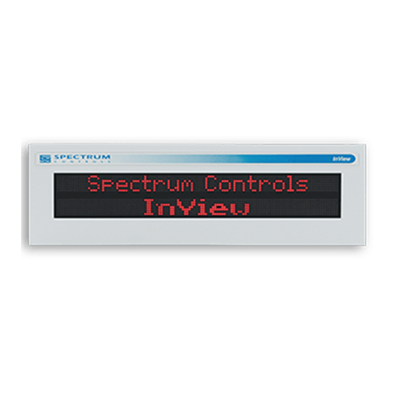
Related Manuals for Spectrum Controls InView Series


Summary of Contents for Spectrum Controls InView Series
-
Page 2: About This Publication
In no event will Spectrum Controls, Inc. be responsible or liable for indirect or consequential damages resulting from the use or application of this equipment. - Page 3 InView Message Displays This equipment has been tested and found to comply with the limits for a NOTE Class A digital device, pursuant to part 15 of the FCC Rules. These limits are designed to provide reasonable protection against harmful interference when the equipment is operated in a commercial environment.
- Page 4 InView Message Displays User’s Manual 0300277-02 Rev. D...
-
Page 5: Table Of Contents
InView Message Displays Table of Contents ABOUT THIS PUBLICATION ..........................II IMPORTANT USER INFORMATION ........................II CHAPTER 1 INSTALLING INVIEW MARQUEE MESSAGE DISPLAY ................ 1-1 1.1 I ............................1-1 ECTION NTRODUCTION 1.2 W ........................1-1 ECTION IRE AND AFETY UIDELINES 1.3 C ........................ - Page 6 InView Message Displays 3.1 U PLC5 O ........................ 3-1 ECTION SE A HANNEL 3.2 U SLC 5/03, 5/04, 5/05 O ................. 3-2 ECTION SE AN HANNEL 3.3 U ..................3-3 ECTION SE A ICRO OGIX HANNEL ERO OR 3.4 U ..................
- Page 7 InView Message Displays ..............................B-4 PECIFICATIONS EMI C ..............................B-5 OMPLIANCE ................................. B-5 ERTIFICATIONS 2706-P42C2-SC 2706-P44C2-SC D ..................B-5 IRING THE ISPLAYS 2706-P42C2-SC 2706-P44C2-SC D ................. B-13 OUNTING THE ISPLAYS 2706-P4 C2 D ..................B-17 ISPLAY ANGUAGE ESSAGE ORMATTING ODES ............................
- Page 8 viii InView Message Displays User’s Manual 0300277-02 Rev. D...
-
Page 9: Chapter 1 Installing Inview Marquee Message Display
Introduction These instructions show you how to change the serial address, and how to mount InView series signs with NEMA Types 4, 4X, and 12 enclosures. These signs are intended for indoor or outdoor use depending on the NEMA standard. -
Page 10: Section 1.3 Change The Serial Address
Chapter 1: Installing InView Message Display AVERTISSEMENT Actions ou situations risquant de provoquer une explosion dans un environnement dangereux et d’entraîner des blessures pouvant être mortelles, des dégâts matériels ou des pertes financières. Power wiring must be in accordance with Class I, Class II and Class III NOTE Division 2 wiring methods (Articles 501-4(b), 502-4(b) and 503-3(b) of the National Electrical Code, NFPA 70) and in accordance with the local... - Page 11 Chapter 1: Installing InView Message Display To connect the 2706-P42-SC and 2706-P44-SC displays: 1. Remove the power supply cover by unscrewing its six screws. Save the screws for a later step. It is recommended that you install power and serial wires at the bottom of NOTE the power supply enclosure to reduce noise from power wires crossing serial wires.
- Page 12 Chapter 1: Installing InView Message Display 4. Strip the wires back 6.35 mm (1/4-in.). Connect the incoming electrical wires. Be sure to place the wires so they are not caught by screws when replacing NOTE the power supply cover, and also so that they do not interfere with fan operation.
-
Page 13: Tb1-Full
Chapter 1: Installing InView Message Display 1.4.1 TB1-Full Pin Name Pin Name RS-485+ +5 V RS-485- RS-232 TX RS-232 RX Shield 6. Connect the incoming serial wires. TB1 may be used for incoming RS-232 or RS-485 serial connections. They cannot be connected at the same time. RS-485 is recommended to reduce undesirable electrical interference. - Page 14 Chapter 1: Installing InView Message Display 1.4.2 TB1-RS-485 Pin Name Pin Name RS-485+ RS-485- Shield 1.4.3 TB1-RS-232 Pin Name Pin Name +5 V RS-232 TX RS-232 RX 7. P1 can be used for incoming RS-232 only, although it is optional and not recommended.
-
Page 15: Section 1.5 Mount The 2706-P42-Sc And 2706-P44-Sc Displays
Chapter 1: Installing InView Message Display Section 1.5 Mount the 2706-P42-SC and 2706-P44-SC Displays Only qualified personnel should install InView displays. InView displays NOTE are for indoor use only and should not be exposed to direct sunlight. Mounting hardware that is used to hang or suspend signs must be capable of supporting at least four times the total weight of any/all signs mounted together. -
Page 16: Wall Mount
Chapter 1: Installing InView Message Display 1.5.1 Wall Mount To mount a display on a wall: 1. Remove the 4 screws and end cap from one end of the sign. 2. Slide one of the wall mounting brackets onto the back of the sign until it is approximately 13 mm (0.5 in.) away from the end of the sign. - Page 17 Chapter 1: Installing InView Message Display 5. Replace the end cap using the 4 screws removed in Step 1 above. 6. Torque the screws to 2.7 Nm (24 lb-in). 7. Repeat Steps 1 to 6 for the other end of the sign. Approximate distances between the bracket holes, center-to-center, are shown below.
- Page 18 1-10 Chapter 1: Installing InView Message Display Do not tighten the nut at this time. 10. Match the alignment holes of the brackets on the sign with the alignment holes of the brackets on the wall so that the sign is at the desired viewing angle.
-
Page 19: Ceiling Mount
Chapter 1: Installing InView Message Display 1-11 1.5.2 Ceiling Mount To mount the display to the ceiling: 1. Remove one screw from the top of the end cap. 2. Line up a ceiling bracket with the top hole on the sign’s end cap so the bracket fits in the indentation. -
Page 20: Stack Mount
1-12 Chapter 1: Installing InView Message Display 1.5.3 Stack Mount Up to 4 signs can be hung together vertically (‘stacked’). Mounting system NOTE for stack mounting must support a minimum of four times the total weight of all signs being stacked. Possible crush Hazard. -
Page 21: Back-To-Back Mount
Chapter 1: Installing InView Message Display 1-13 5. For each end of the signs, secure the stacking bracket from the bottom sign to the next sign using one of the screws removed in Step 3 and torque to 2.7 Nm (24 lb-in). 6. - Page 22 1-14 Chapter 1: Installing InView Message Display Do NOT fasten the top screws to the end caps. The top screws are used to NOTE fasten the ceiling mounting brackets to the end caps in the next step. 3. Attach ceiling mounting brackets to all the end caps and torque the screws to 2.7 Nm (24 lb-in).
-
Page 23: Section 1.6 Mount The 2706-P72-Sc And 2706-P74-Sc Series Nema 4 And 4X Models
Chapter 1: Installing InView Message Display 1-15 Use chains capable of supporting 4 times the total weight of the sign(s). NOTE Section 1.6 Mount the 2706-P72-SC and 2706-P74-SC Series NEMA 4 and 4X Models To mount the sign: 1. Attach the two sign brackets to a wall, ceiling, or other surface. Be sure to place the brackets so the bracket flanges face appropriately as shown below. - Page 24 1-16 Chapter 1: Installing InView Message Display Keep a minimum 2.54 cm (1.0 in.) clearance on all sides of the sign for NOTE adequate ventilation. Hazardous voltage. WARNING Contact with high voltage may cause death or serious injury. Always disconnect power to sign prior to servicing. Tension dangereuse.
-
Page 25: Tb1 Full
Chapter 1: Installing InView Message Display 1-17 3. Screw the inside and outside ends of the connector together until water- tight. 4. Strip the electrical wires back 6.35 cm (0.25 in.). 5. Connect the wires by screwing the end of each wire into the power connection. - Page 26 1-18 Chapter 1: Installing InView Message Display 7. Connect the incoming serial wires per pinout. TB1 can be used for incoming RS-485 or RS-232 serial connection. They cannot be connected at the same time. RS-485 is recommended to reduce undesirable electrical interference. 1.6.2 TB1-RS-485 Pin Name Pin Name...
-
Page 27: Section 1.7 Mount The 2706-P92-Sc And 2706-P94-Sc Displays
Chapter 1: Installing InView Message Display 1-19 Section 1.7 Mount the 2706-P92-SC and 2706-P94-SC Displays To mount the sign: 1. Attach the two sign brackets to a wall, ceiling, or other surface. 2. Be sure to place the brackets so the bracket flanges face appropriately as shown below. - Page 28 1-20 Chapter 1: Installing InView Message Display 6. To hold the sign in place, insert the remaining bolts into the desired viewing angle hole on each bracket. Keep a minimum 2.54 cm (1.0 in.) clearance on all sides of the sign for NOTE adequate ventilation.
-
Page 29: Section 1.8 Electrical Connections For 2706-P92-Sc And 2706-P94-Sc Signs
Chapter 1: Installing InView Message Display 1-21 Section 1.8 Electrical Connections for 2706-P92-SC and 2706-P94-SC Signs Hazardous voltage. WARNING Contact with high voltage may cause death or serious injury. Always disconnect power to sign prior to servicing. Maintain Separation of circuits. Route the incoming power directly to the power connection terminal block. - Page 30 1-22 Chapter 1: Installing InView Message Display Use chains capable of supporting 4 times the total weight of the signs. NOTE 3. Strip the electrical wires back 6.35 mm (0.25 in.). 4. Insert the wires into the appropriate terminal connection and tighten the screw to 0.79 Nm (7 lb-in).
-
Page 31: Tb2-Aux +5 V
Chapter 1: Installing InView Message Display 1-23 1.8.1 TB1-RS-485 Pin Name Pin Name CH A SHLD CH B COMM TERM 1.8.2 TB2-AUX +5 V Pin Name Pin Name +5 V 1.8.3 TB3-RS-232 Pin Name Pin Name EGND 1.8.4 Ethernet (RJ45) To maintain noise immunity, use shielded Ethernet cable. -
Page 32: Download Port (Rj12)
1-24 Chapter 1: Installing InView Message Display 1.8.5 Download Port (RJ12) The 2706-PCable1-SC is used for downloading messages only and must NOTE be removed after downloading is complete. Pin Name Pin Name AUX +5 V 7. Carefully close the front of the sign case and turn the half-turn latches to the right with a large screwdriver. -
Page 33: Electrical Connections For 2706-P22-Sc Display
Chapter 1: Installing InView Message Display 1-25 Panel Cutout Dimensions for 2706-P22-SC Display 1.9.1 Electrical Connections for 2706-P22-SC Display The InView display requires 18 to 30 VDC, 0.5 A at 18 VDC. The 2706-PCable1-SC is used for downloading messages only and must NOTE be removed after downloading is complete. - Page 34 1-26 Chapter 1: Installing InView Message Display To satisfy all agency requirements and ensure proper operation, power this NOTE product using a 24 VDC, class 2 SELV power supply. Use a small screwdriver to remove the terminal block’s header to ease NOTE product wiring.
-
Page 35: Dip Switch Settings For 2706-P22-Sc Display
Chapter 1: Installing InView Message Display 1-27 RS-232 Connection Pin Name Pin Name 1.9.2 DIP Switch Settings for 2706-P22-SC Display The 2706-PCable1-SC is used for downloading messages only, and must be removed after downloading is complete. Disconnect power from the InView display before setting any switch. WARNING Switch settings are scanned only on power-up. -
Page 36: Section 1.10 Download A Message Application
1-28 Chapter 1: Installing InView Message Display Section 1.10 Download a Message Application InView message applications are created using the InView messaging software (2706-PSW1-SC). After creating the Message Application, you need to download it into your InView display memory. InView applications can be downloaded using: •... -
Page 37: 1761-Net-Aic (Aic+)
Chapter 1: Installing InView Message Display 1-29 1.11.1 1761-NET-AIC (AIC+) 1.11.2 RS-485 Echo The RS-485 echo feature addresses the issue of increased network traffic often caused by multiple node addresses and high consumption of communication bandwidth. The display’s design enables users to daisy-chain numerous InView displays off an InView P9x-SC via the RS-485 communication network. -
Page 38: Section 1.12 Global Addressing
1-30 Chapter 1: Installing InView Message Display RS-232 port, RJ12 download port, or the RJ45 10/100 base-T Ethernet port, are echoed out the RS-485 port. An InView master display inspects the incoming packets and determines if the packet is addressed to itself and take the appropriate action. The master ignores all packets that are not addressed to itself. - Page 39 Chapter 1: Installing InView Message Display 1-31 There is an impedance of 120 ohms built into each AIC and AIC+ as required by the RS-485 specification. Jumper terminals 5 and 6 of the AIC or AIC+ for end- of-line termination. End-of-line InView display should have a terminating resistor in RJ11 NOTE (P1).
- Page 40 1-32 Chapter 1: Installing InView Message Display User’s Manual 0300277-02 Rev. D...
-
Page 41: Chapter 2 Inview System Connectivity
Chapter 2 InView System Connectivity This chapter demonstrates how the InView display connects to control networks. In the following chapters we show controller configuration and sample ladder for serial ASCII networks. This chapter also discusses how to set-up the display attributes, communications and create messages. -
Page 42: Tb1 Connections
Chapter 2: InView System Connectivity Section 2.4 TB1 Connections TB1-FULL Pin Name Pin Name RS-485+ +5 V RS-485- RS-232 TX RS-232 RX Shield Section 2.5 2706-P22-SC Display This display operates at 18 to 30 VDC. It has three communication ports. These are the RJ12, DB-9, and a six-position terminal block port. -
Page 43: 2706-P22R-Sc Display Communication Connections
Chapter 2: InView System Connectivity 2.5.1 2706-P22R-SC Display Communication Connections RJ11 Connections Pin Name Pin Name +5 V RS-485 Connections Pin Name Pin Name E-GND CH A SHLD CH B COMM TERM RS-232 Connection Pin Name Pin Name The 2706-P22R-SC display has a ten-position dip switch. The first eight positions are used to set the address of the display. -
Page 44: 2706-P22-Sc Display Dip Switch Settings
Chapter 2: InView System Connectivity After one complete LED scan is done, a RAM check is performed, and the NOTE display’s memory is cleared. To ensure that the display’s memory is not cleared, turn off power to the display after the LED block test is performed. - Page 45 Chapter 2: InView System Connectivity When you enable the RS-485 echo function, this allows any packets that come in on COM 0 (download, RJ12 port), COM 1 (RS-232, TB3 port), and the Ethernet TCP/IP port to be sent out the RS-485 port. This allows Ethernet TCP/IP and other communication protocols to be converted to RS-485 by a single 2706-P92- SC or 2706-P94-SC and then sent out to multiple RS-485 networked displays.
-
Page 46: Additional Information For 2706-P9X-Sc Displays
Chapter 2: InView System Connectivity 2.6.2 Additional Information for 2706-P9x-SC Displays For additional information on communication port wiring and display configuration, refer to the InView Marquee Message Display User Manual, publication 0300281-02_A0(MANUAL_2706-UM016D-EN-P). This product contains a Lithium battery. See publication 0100214- 02_A0(INSTALLATION_INSTRUCTIONS_2706-IN009C-EN-P) for information regarding battery replacement and disposal. - Page 47 Chapter 2: InView System Connectivity Multiple Communication Rate Support The 2706-P92C-SC and 2706-P94C-SC displays allow you to select serial communication rates of 9600, 19200, or 38400 bps. The communication rates are both hardware (dip switches) and software selectable. For selecting the communication rate using the dip switches, see the NOTE section entitled Dip Switch Settings.
- Page 48 Chapter 2: InView System Connectivity 3. Choose the communication rate you wish to set the display at and click on the Set button: There is no confirmation that the command was sent. The display must be NOTE power cycled to view the new communication rate settings. Isolated Communication Ports The isolated communication ports consist of RS-232, RS485, 10/100 Ethernet port and a RS-232 download port.
-
Page 49: Power-Up Messages
Chapter 2: InView System Connectivity Flash Programmable Firmware The programmable Compact Flash card is located inside the 2706-P9x-SC display on the controller board as shown below. The Compact Flash card must be at least 32 MB; anything less is not NOTE supported. - Page 50 2-10 Chapter 2: InView System Connectivity Display Setup To set up your display: 1. Start the InView messaging software. 2. Create a project. The software prompts for a project file name, a project name, and description. Once this is done, the project name and description appears in the Displays box.
- Page 51 Chapter 2: InView System Connectivity 2-11 To set the IP address: 1. Select the display you created, which use the Ethernet module. 2. Right click on the display and select Edit Display: Double clicking on the display takes you to the same window. NOTE 3.
- Page 52 2-12 Chapter 2: InView System Connectivity Under the section with the Heading TCP/IP settings is the Configure Communications button. 4. Click to access the Ethernet TCP/IP Communications window to set the IP address. 5. In the IP Address field, specify the IP address. 6.
- Page 53 Chapter 2: InView System Connectivity 2-13 If the Invalid IP Address window appears, click OK, choose a different NOTE desired IP Address, and click the Setup button again. Once a valid IP Address is entered, the following window should appear saying it is ready to assign an IP address: 10.
- Page 54 2-14 Chapter 2: InView System Connectivity However, upon successfully setting up the Gateway Address and Subnet Mask, the following message appears telling you to cycle power to the module: After the IP Address, Gateway Address and Subnet Mask have all been established, click the OK button on the bottom of the Ethernet TCP/IP Communications window.
- Page 55 Chapter 2: InView System Connectivity 2-15 Message File Additional Information Additional tasks covered in the following section are: • Attach a Note to a Message • Text Color • Date, Time and Variables • Category • Message Priorities • Pause •...
- Page 56 2-16 Chapter 2: InView System Connectivity medium priority message. An alarm message of high water temperature shutdown is a high priority message. In our example, the water temperature is part of the generator signals that are constantly being monitored and displayed as low priority signals in the message queue (the message queue can hold up to 64 messages).
- Page 57 Chapter 2: InView System Connectivity 2-17 networked signs via Ethernet TCP/IP. See the 2706-PENET1-SC documentation for more information on using this communication option. Download Messages Once the message file has been created, there are several download Options: • Download the entire file - Download Message File and •...
- Page 58 2-18 Chapter 2: InView System Connectivity Trigger Message and Broadcast Trigger Message Trigger Message and Broadcast Trigger Message allows up to 64 messages selected from the message list to be displayed after download. This is the message queue. Each message is displayed for the amount of the pause time that is set when the message is created.
-
Page 59: Chapter 3 Serial Ascii Communications
Chapter 3 Serial ASCII Communications Section 3.1 Use a PLC5 Out Channel Zero To use a PLC5 out Channel Zero on a display: 1. Create a new application. 2. Set up the channel configuration. 3. Create a file type String (ST). You insert ASCII/Hex commands in this file. -
Page 60: Section 3.2 Use An Slc 5/03, 5/04, Or 5/05 Out Channel Zero
Chapter 3: Serial ASCII Communications Section 3.2 Use an SLC 5/03, 5/04, or 5/05 Out Channel Zero The SLC processor is set up very similar to the PLC processor. The SLC processor uses the same ladder logic as the PLC processor shown below. To use an SLC processor out Channel Zero on a display: 1. -
Page 61: Section 3.3 Use A Micrologix Out Channel Zero Or One
Chapter 3: Serial ASCII Communications 2. Under the General tab, make sure the mode for channel 0 is set to USER. Section 3.3 Use a MicroLogix Out Channel Zero or One The MicroLogix processor is set-up similar to the SLC processor. They both use RSLogix 500 software to communicate;... -
Page 62: Section 3.4 Use Controllogix Processor Out Channel Zero
Chapter 3: Serial ASCII Communications In this example the ASCII is done using channel 1. Section 3.4 Use ControlLogix Processor Out Channel Zero To use a ControlLogix processor out Channel Zero on a display: 1. Open a new application. 2. Set up the controller properties by right-clicking on the controller name and selecting properties and then the serial port tab as follows: 3. -
Page 63: Section 3.5 Use The Compactlogix Processor Out Channel Zero Or One
Chapter 3: Serial ASCII Communications Section 3.5 Use the CompactLogix Processor Out Channel Zero or One To use a CompactLogix processor out Channel Zero on a display: 1. Open a new application. 2. Set up the controller properties by right-clicking on the controller name and selecting properties and then the serial port tab. -
Page 64: Section 3.6 Use Flexlogix Processor Out Channel Zero
Chapter 3: Serial ASCII Communications Section 3.6 Use FlexLogix Processor Out Channel Zero To use a FlexLogix Processor out Channel Zero on a display: 1. Open a new application. 2. Set up the controller properties by right-clicking on the controller name and selecting properties and then the serial port tab: 3. -
Page 65: Chapter 4 Inview Protocol
Chapter 4 InView Protocol Section 4.1 Introduction The purpose of this chapter is to show the protocol that is required to trigger messages and update variables on InView displays with the InView protocol. In general, messages are downloaded through the software and stored within the display memory. -
Page 66: The Ctrl-V Function Frame - Numeric Variables
Chapter 4: InView Protocol Control-T Frame Description Data Acceptable Values Description [CTRL][T[ ASCII 1 ... 4000 (Decimal) \31 to \34\30\30\30 Message number MSG # 4095 (Decimal) \34\30\39\35 Background message number -1 (Decimal) \2D\31 Backslash Backslash 1 (Decimal) = Priority message Function 2 (Decimal) = dd message Message Function... -
Page 67: The Ctrl-V Function Frame - Alphanumeric Variables
Chapter 4: InView Protocol Control-V Frame Format Optional Variable Display Name [CTRL][V] Backslash Variable # Backslash <CR> Data Address The following table indicates the values to use in the Control-V format, Control-V Frame Description Data Acceptable Values Description [CTRL][V[ ASCII Variable -32768 to 32767 (ASCII \2D\33\32\37\36\38 to... -
Page 68: Examples Of The Control-T Function
Chapter 4: InView Protocol Control-V Frame Format – Alphanumeric Optional ‘Variable Display Name [CTRL][V] Backslash Variable # Backslash <CR> Data’ Address The following table indicates the values to use in the Control-V format, Control-V Frame Description - Alphanumeric Data Acceptable Values Description [CTRL][V[ ASCII... - Page 69 Chapter 4: InView Protocol shown on one or all displays. Trigger a Message on all Displays using Priority Messaging A message can be shown on all displays one of three different ways. These examples show the Control-T function being used to show message number 45 on all displays.
- Page 70 Chapter 4: InView Protocol Add a Message on all Displays Display Name [CTRL][T] MSG # Backslash Function Backslash Return Address ASCII 2011 \32\30\31\31 \ \32\35\35 Adding a Message on a Specific Display The following adds message 348 to display address 055. Adding a Message on a Specific Display Display Name...
-
Page 71: Section 4.3 Examples Of The Control-V Function
Chapter 4: InView Protocol and automatically displays the background message (4095) without adding the background message number to the message queue. Display Name [CTRL][T] MSG # Backslash Function Backslash Return Address ASCII \2D\31 \32\34 The following removes all messages on display address 024 and adds the background message (4095) to the message queue using priority messaging. -
Page 72: Section 4.4 Update Variable On A Specific Display
Chapter 4: InView Protocol Variable Variable Display Name [CTRL][V] Backslash Backslash Return Address Data 2395 ASCII \32\33\39\35 \32\35\35 Section 4.4 Update Variable on a Specific Display Update variable 5 with the value of 87 on display address 006. Update a Variable on a Specific Display Variable Variable Display... -
Page 73: Section 4.7 How Inview Sign Communication Protocol Is Used With Modbus Ascii Protocol
Chapter 4: InView Protocol Section 4.7 How InView Sign Communication Protocol is used with Modbus ASCII Protocol There are two different modes of transmission used with Modbus protocol, Modbus ASCII and Modbus RTU. In this case, Modbus ASCII is used. Modbus ASCII protocol is used to accomplish such functions as Priority Messaging, Add a Message, Remove a Message, Update Variables, and reading register in the Message Queue or Variable. - Page 74 4-10 Chapter 4: InView Protocol • Format: Number of bits per character - 1 start bit, 7 data, 1 (optional) parity bit, 1 or 2 stop bits. For the products, the data communication rate and format is 9600 baud (maximum), 1 start bit, 7 data bits, even parity, 2 stop bits. InView Display Memory Map Information transmitted to the displays writes or reads information into holding registers.
- Page 75 Chapter 4: InView Protocol 4-11 Function Function Modbus Meaning Action Code Code Hex Used to preset multiple registers in a Preset Multiple display (Add/Remove a Message or Registers Update Variables). Methods of Transportation Modbus Method Description Function Display Action Code Writes information into registers 101 Add/Remove a Message Triggers a message(s) on...
- Page 76 4-12 Chapter 4: InView Protocol ASCII Message Frame Format Error Beg of Address Function Data Check Frame (LRC) 2-char 2-char N × 4-char 2-char 0×0d 0×0a 16-bits N × 16-bits 16-bits 16-bits Beginning of Frame Field Each transmission will start with a colon (:) and is used to signal the receiving device that message packet follows.
- Page 77 Chapter 4: InView Protocol 4-13 Simulated Query and Response End Of File Field This field is used to signify the end of file for the transmission. It uses a Carriage Return (0×0d). Line Feed Field This is the ready to respond field file (LF) and uses a line feed (0×0a). Longitudinal Redundancy Check (LRC) Error Detection and Calculation Some sort of error detection is needed, because communication errors can occur...
- Page 78 4-14 Chapter 4: InView Protocol Examples of Modbus ASCII Functions The following sections show examples of Modbus ASCII protocol Query/Response transmissions to/from a display for each command instruction listed above. Modbus ASCII will write/read to the holding registers in the display.
- Page 79 Chapter 4: InView Protocol 4-15 Transmission for Enabling the Heartbeat Function Beg of Ready to rec. ADDR FUNC DATA Frame ADDR ADDR response ^AZFF^BE01^D9C See InView Display Communication Protocol Functions and Descriptions NOTE on for further explanation of the InView sign protocol being used. Response: NONE Disable the Heartbeat Function Transmission is as follows:...
- Page 80 4-16 Chapter 4: InView Protocol The Clearing Memory string may be required prior to the NOTE downloading of messages. Transmission is as follows: Transmission for Clearing Display Memory Beg of Ready to rec. ADDR FUNC DATA Frame ADDR ADDR response ^AZ00^BE$^D See InView Display Communication Protocol Functions and Descriptions NOTE...
- Page 81 Chapter 4: InView Protocol 4-17 Query for Clearing the Message Queue with 06 Frame Guaranteed Ready to Beg of ADDR FUNC DATA rec. Frame ADDR ADDR Error response FFFF Response: The normal response to a function 06 is to echo (or re-transmit) the query after the holding register is updated.
- Page 82 4-18 Chapter 4: InView Protocol Transmission for Clearing the Message Queue Ready to Beg of ADDR FUNC DATA rec. Frame ADDR ADDR Error response FFFF Response: NONE Set Time in Broadcast Mode with 24-Hour Format This command is used to set the time and the format for the time in all displays. This is primarily done using the automation software to synchronize the time in the displays with the computer.
- Page 83 Chapter 4: InView Protocol 4-19 This is primarily done using the automation software to synchronize the time in the displays with the computer. This requires two separate transmissions. First, set the time and format for the time. Second, clear the queue. The following is an example of setting the time to 1035 and the format for the time to be 24 hour (military) format.
- Page 84 4-20 Chapter 4: InView Protocol Transmission for Setting Date Ready to Beg of ADDR FUNC DATA rec. Frame ADDR ADDR response ^AZ00^BE;01040^D See InView Display Communication Protocol Functions and Descriptions NOTE on for further explanation of the InView sign protocol being used. Response: NONE 300 ms pause.
- Page 85 Chapter 4: InView Protocol 4-21 A message preview is not recommended for run-time. NOTE Four separate types of transmissions are required for message preview. This is primarily done using the automation software to preview a message. First, clear the Message Queue. Second, download the message to the appropriate memory partition.
- Page 86 4-22 Chapter 4: InView Protocol Download Message 1 to be Previewed Ready to Beg of ADDR FUNC DATA rec. Frame ADDR ADDR response ^AZ00^BA2001^[”b^I^^1^\1Hello^D See InView Display Communication Protocol Functions and Descriptions NOTE on for further explanation of the InView sign protocol being used. Response: NONE 300 ms pause.
- Page 87 Chapter 4: InView Protocol 4-23 Download Messages Messages can be downloaded to the display so that they can be triggered (or activated) at a later time. The download of messages is generally done using the InView messaging software but can be done from ladder logic using the instructions below.
- Page 88 4-24 Chapter 4: InView Protocol Transmission for Downloading Message 1 (Example 1) Ready to Beg of ADDR FUNC DATA rec. Frame ADDR ADDR response ^AZ00^BA2001^[”b^I^^1^\1Priority High^D See InView Display Communication Protocol Functions and Descriptions NOTE on for further explanation of the InView sign protocol being used. Response: NONE 300 ms pause Download message file #002...
- Page 89 Chapter 4: InView Protocol 4-25 300 ms pause 3. Clear the message queue. This transmission is used to remove all currently running messages downloaded to the queue. Transmission is as follows: Transmission for Clearing the Message Queue Ready to Beg of ADDR FUNC DATA...
- Page 90 4-26 Chapter 4: InView Protocol Transmission for Downloading Message 1 (Example 2) Ready Beg of ADDR FUNC DATA to rec. Frame ADDR ADDR response ^AZ00^BA2001^[”b^I^^1^\1Hello^D See InView Display Communication Protocol Functions and Descriptions NOTE on for further explanation of the InView sign protocol being used. Response: NONE 300 ms pause Download message file #0002...
- Page 91 Chapter 4: InView Protocol 4-27 message #0015 and removing message #0045 from the message queue on display number 019. Transmission is as follows: Query to Add/Remove the Message Queue Beg of BYTE ADDR FUNC QUANTITY DATA Frame ADDR ADDR 0002 000F 002D LRC Error...
- Page 92 4-28 Chapter 4: InView Protocol Priority Messaging using a Modbus ASCII Query (Recommended) This method writes to the first register in the message queue (40103). When this happens, the previous message in the queue is replaced with the new message to be loaded.
- Page 93 Chapter 4: InView Protocol 4-29 Query for Updating a Variable Register Beg of Ready to rec. ADDR FUNC DATA Frame ADDR ADDR Error response 0264 Response: The normal response to a function 06 is to echo (or re-transmit) the query after the holding register is updated.
- Page 94 4-30 Chapter 4: InView Protocol Beg of BYTE ADDR FUNC QUANTITY DATA Frame ADDR ADDR 0003 00017 02DE 0007 LRC Error Ready to rec. response Use of the Guaranteed mode for variable updates means messages may not NOTE be displayed as expected. Response: The normal response to a function 10 query is to echo the address, function code, starting address and the number of registers that were loaded.
- Page 95 Chapter 4: InView Protocol 4-31 Response for Requesting Message Data DATA DATA DATA Beg of BYTE OUTPUT OUTPUT OUTPUT DATA OUTPUT ADDR FUNC Frame COUNT REG L.O. REG H.O. REG L.O. 0067 H.O. 0066 0066 0067 Ready to DATA OUTPUT DATA OUTPUT LRC Error rec.
-
Page 96: Inview Display Communication Protocol Functions And Descriptions
4-32 Chapter 4: InView Protocol Response for Requesting Variable Data DATA DATA DATA Beg of BYTE OUTPUT OUTPUT OUTPUT DATA OUTPUT ADDR FUNC Frame COUNT REG L.O. REG H.O. REG L.O. 0003 H.O. 0002 0002 0003 Ready to DATA OUTPUT DATA OUTPUT LRC Error rec. - Page 97 Chapter 4: InView Protocol 4-33 Basic InView Message Format Type Display Command Message Message Insert Insert Message <SOH> <STX> Code Address Code Control Attributes Objects Variables Data Name Description <SOH> Start of Header Type Code Display type with which to communicate Display Address Address of display where information is written <STX>...
- Page 98 4-34 Chapter 4: InView Protocol Command Code <STX> Priority Command Description ASCII Description ASCII Description ASCII Start of Write Text Text file Write Special Medium Function High Command Code, continued Message Control Message # <ESC> Display Position Description ASCII Description ASCII Description ASCII...
- Page 99 Chapter 4: InView Protocol 4-35 Message Attributes Character Font Character Color Character Width/Height Description ASCII Description ASCII Description ASCII 10 High 1A36 Double High ^Q^]21 111D3231 Standard 16 High Fancy (Full 1A38 Height) 16 High Standard 1A39 (Full Height 24/32 Fancy ^Z8^E1 1A380531 24/32 High...
- Page 100 4-36 Chapter 4: InView Protocol Insert Variable – Numeric Message Field <EOT> Call Variable Message or Data Description ASCII Description ASCII Description ASCII (space) End of Variable 1 ^P00 103030 ASCII Data – DEL Transmission Variable 2 ^P01 103031 … …...
- Page 101 Chapter 4: InView Protocol 4-37 <SOH> Type Code Display Address Description ASCII Description ASCII Description ASCII Start of Display All displays 3030 Header Address <STX> Command Code Command Function Description ASCII Description ASCII Description ASCII Write Start of Clear Special Text Memory Function...
- Page 102 4-38 Chapter 4: InView Protocol Command Code <EOT> Description ASCII Description ASCII Message Size 0032 30303332 End of Transmission (minimum) 50 Bytes Set Time Time can be set in either AM/PM format or 24 hour (military) format. The following shows the valid values for this command: Special Function Command to Set Time and Time Format <SOH>...
- Page 103 Chapter 4: InView Protocol 4-39 <STX> Command Code <ETX Description ASCII Description ASCII Description ASCII Set Time Start of ‘S Format 2753 End of Text Text AM/PM Set Time ‘M Format 24 Hr 274D (Military) <EOT> Description ASCII End of Transmission Set Date This command is used to set the date.
- Page 104 4-40 Chapter 4: InView Protocol Command Code, continued <ETX Set Date Set Hour and Minutes HhMm ASCII Description ASCII January 4, 2001 (Example) 010401 303130343031 End of Text December 5, 2002 (Example) 120502 31323035303 <STX> Command Code <ETX Description ASCII Description ASCII Description...
- Page 105 Chapter 4: InView Protocol 4-41 Command Code, continued <EOT> Set Day of Week ASCII Description ASCII Thursday Friday Saturday Set Serial Address This command changes a serial address for a display. Special Function Command to Set Serial Address <SOH> Type Code Display Address Description ASCII...
-
Page 106: Ascii Characters
4-42 Chapter 4: InView Protocol P44 Series Display Position Description Fill Displays two lines of 7 pixel characters. Valid Modes used in P72 Series Displays P74 Series Display Description Comment 1 Comment 2 Position If the top line has If the top line has only only two rows of one row of text, the Displays text on top line only. -
Page 107: Chapter 5 Inview Control And Inview Control Api
Chapter 5 InView Control and InView Control API Section 5.1 Introduction The purpose of this chapter is to describe the API for the InView control. The chapter is divided into two sections. The first section is a quick overview on how to use the control. -
Page 108: Section 5.4 Properties
InView Control and InView Control API Section 5.4 Properties InViewCtrl Properties Description Sets/Returns method by which the control ConnectMode communicates with the display. Sets/Returns IP address used to communicate with NetworkAddress the display. Sets/Returns socket port used to communicate with NetworkPort the display. - Page 109 Chapter 5: InView Control and InView Control API InViewCtrl Methods Description RemoveMessage Stops a message from running on the display. SingleMessage Stops any currently running messages on the display and run a single previously downloaded message. UpdateVariable Updates the value of a single variable. UpdateVariableEx Updates the values of a range of variables.
-
Page 110: Section 5.6 Properties
InView Control and InView Control API Section 5.6 Properties InViewCtrl Properties Properties Description ConnectMode Syntax object.ConnectMode = value Read/Write (short) Values 0 - Serial Communication 1 - TCP/IP Communication Default Description This property is used to set the method by which the control communicates with the display NetworkAddress Syntax... - Page 111 Chapter 5: InView Control and InView Control API InViewCtrl Properties Properties Description SerialBaudRate Syntax object.SerialBaudRate = value Read/Write [long] Values 110, 300, 600, 1200, 2400, 4800, 9600, 14400, 19200, 28800, 38400, 56000, 57600, 115200, 128000, 256000 Default 9600 Description This property is used to set the serial baud rate that the control will use to communicate with the display.
- Page 112 InView Control and InView Control API InViewCtrl Properties Properties Description SerialStopBits Syntax object.SerialStopBits = value Read/Write [float] Values 1 and 2 Default Description This property is used to set the serial stop bits that the control will use to communicate with the display.
- Page 113 Chapter 5: InView Control and InView Control API InViewCtrl Properties Properties Description HeartBeat Syntax object.Heartbeat = value Read/Write [short] Values 0 - No heartbeat from control 1 - Heartbeat generated by control 2 - Heartbeat disabled Default Description This property is used to set how the control will handle the heartbeat requirement of the display.
-
Page 114: Section 5.7 Methods
InView Control and InView Control API Section 5.7 Methods InViewCtrl Methods Properties Description Initialize Syntax HRESULT Initialize() Parameters None Return Value S_OK - Success E_FAIL - Failure Description This method is used to open the COM port or socket that will be used to communicate with the display. - Page 115 Chapter 5: InView Control and InView Control API InViewCtrl Methods Properties Description ClearMemory Syntax HRESULT ClearMemory() Parameters None Return Value S_OK - Success E_FAIL - Failure Description This method is used to reset the display and clear its memory. After clearing memory, the display will be set to 2000 messages of 100 bytes each, and each message slot will be set to a message of Message #n where n is the message number.
- Page 116 5-10 InView Control and InView Control API InViewCtrl Methods Properties Description DownloadMessage HRESULT DownloadMessage( Syntax short nMessageNumber, short nPriority, short nPosition, short nMode, short nSpeed, short nFont, short nColor, BSTR bstrBody) nMessageNumber Parameters The number of the message slot in the display to receive the message. nPriority The priority assigned to the message.
- Page 117 Chapter 5: InView Control and InView Control API 5-11 InViewCtrl Methods Properties Description DownloadMessage This method is used to download a simple message to the display. The Description download message command will be sent to the display address set by continued the DisplayAddress property.
- Page 118 5-12 InView Control and InView Control API InViewCtrl Methods Properties Description RemoveMessage Syntax HRESULT RemoveMessage (short nMessageNumber) Parameters nMessageNumber The number of the message to be removed from the queue of running messages. Return Value S_OK - Success E_FAIL - Failure Description This method is used to trigger a message to stop running on the display.
- Page 119 Chapter 5: InView Control and InView Control API 5-13 InViewCtrl Methods Properties Description UpdateVariable Syntax HRESULT UpdateVariable (short nVariable, long nValue) Parameters nVariable The variable number to update. Valid values are 0 … 99. nValue The new value for the variable. The display is limited to 16-bit numbers, which can be signed or unsigned.
- Page 120 5-14 InView Control and InView Control API InViewCtrl Methods Properties Description SetTime Syntax HRESULT SetTime (DATE dtTime, BOOL fMilitary) Parameters dtTime The time used to update the display’s clock. fMilitary A flag used to indicate if the time should be displayed using 24-hour format.
- Page 121 Chapter 5: InView Control and InView Control API 5-15 InViewCtrl Methods Properties Description ChangeDisplayBaudRate Syntax HRESULT ChangeDisplayBaudRate This method is only short nNewDisplayBaudRate) recognized by the P9x series of Parameters nNewDisplayBaudRate displays. An enumerated value of the currently available baud rates. 0 = 9600 baud, 1 = 19200 baud, and 2 = 38400 baud.
- Page 122 5-16 InView Control and InView Control API InViewCtrl Methods Properties Description ChangeDisplaySubnetMask Syntax HRESULT ChangeDisplaySubnetMask This method is only (BSTR ipaddress) recognized by the P9x series of Parameters ipaddress displays. An IPAddress string with the syntax of NNN.NNN.NNN.NNN, where each octet is between 0 and 255.
- Page 123 Chapter 5: InView Control and InView Control API 5-17 InViewCtrl Methods Properties Description ClearBitmapTable Syntax HRESULT ClearBitmapTable() This method is only Parameters None recognized by the P9x series of Return Value S_OK - Success displays. E_FAIL - Failure Description This method is used to clear the contents of the display’s bitmap table.
-
Page 124: Section 5.8 Temperature Protection In Nema-Rated Enclosures
5-18 InView Control and InView Control API Section 5.8 Temperature Protection in NEMA-Rated Enclosures Some InView signs in NEMA-rated enclosures have automatic temperature controls that help to protect the sign from damage when the internal temperature of the sign is too hot to continue normal operation. If the internal temperature of the sign reaches a pre-determined dimming point, the LED output from the sign is forced into a 50 percent reduced power mode, effectively dimming the brightness of LED output by about 50 percent. -
Page 125: Section 5.9 Additional Resources
Controls, Inc., please ensure that the unit is enclosed in approved ESD packaging (such as static-shielding/metallized bag or black conductive container). Spectrum Controls, Inc. reserves the right to void the warranty on any unit that is improperly packaged for shipment. - Page 126 5-20 InView Control and InView Control API User’s Manual 0300277-02 Rev. C...
-
Page 127: Appendix A: Installing Inview Marquee 2706-P9Xc2-Sc Message Displays
7.5 mm. You may scroll images and characters from right-to-left, or left- to-right, depending on the language. The displays comply with NEMA 4 and IP66 housing standards. If you use the equipment in a manner not specified by Spectrum Controls, NOTE Inc. may impair the protection provided by the equipment. -
Page 128: Ounting The 2706-P92C2-Sc And 2706-P94C2-Sc Displays
Appendix A: Installing InView Marquee 2706-P9xC2-SC Message Displays Mount the sign so that it is easy to disconnect power when servicing. If a display gets too hot during operation, the software is designed to NOTE reduce display brightness or shut the display off. For temperatures at which display reduces brightness and/or shuts down, refer to Temperature Protection in NEMA-Rated Enclosures. - Page 129 Appendix A: Installing InView Marquee 2706-P9xC2-SC Message Displays A-3 5. Tilt the sign to select a viewing angle. 6. To hold the sign in place, insert the remaining bolts into the desired viewing angle hole on each bracket. Keep a minimum 2.54 cm (1.0 in.) clearance on all sides of the sign for NOTE adequate ventilation.
-
Page 130: Wiring The 2706-P92C2-Sc And 2706-P94-Sc Displays
Appendix A: Installing InView Marquee 2706-P9xC2-SC Message Displays Back-to-Back Mount To connect the sign: 1. Attach the brackets to the sign in the ceiling mount position with the hex bolts supplied. 2. Match the signs together back-to-back and connect them together using a total of six 5/16”... - Page 131 Appendix A: Installing InView Marquee 2706-P9xC2-SC Message Displays A-5 1. Disconnect power to the InView display. 2. Loosen the right-hand drawer by unscrewing its 4 screws until you can pull the drawer out. Set the screws aside for later step. Comms Power Drawer...
- Page 132 Appendix A: Installing InView Marquee 2706-P9xC2-SC Message Displays Wire Color Wire Name Black Line (Hot) connect to L (White terminal) White Neutral connect to N (Blue terminal) Green Ground connect to G (Green and Yellow terminal) 6. If you are installing a Communications Module in the left-hand drawer, install it now (refer to the 0300289- 05_A0(Users_Guide_InView_COMMS_MODULE) manual) for additional details.
-
Page 133: Specifications
Appendix A: Installing InView Marquee 2706-P9xC2-SC Message Displays A-7 10. Replace the drawers using the 4 screws. Torque the screws to 1.8 N-m (16 in-lbs) for NEMA 4 models, and 3 N-m (26.5 in-lbs) for NEMA 4X models. 11. Connect the power wiring to a power source. Specifications Display Specifications 2706-P92C2-SC... - Page 134 Appendix A: Installing InView Marquee 2706-P9xC2-SC Message Displays 2706-P9xC2 Display Language Message Formatting Codes The following message formatting codes have been added for the C2 displays: Mode Description ASCII Rotate right Justification Description ASCII Right 1E32 Message Attributes Description ASCII 20High 1A32 20Fancy...
-
Page 135: Appendix B: Installing Inview Marquee 2706-P4Xc2-Sc Message Displays
Appendix B: Installing InView Marquee 2706-P4xC2-SC Message Displays Overview These instructions show you how to mount InView 2706-P42C2-SC and 2706- P44C2-SC signs with NEMA Type 12 enclosures. Environment Requirements Observe the following requirements: • These displays are for indoor use only. They should not be exposed continuously to sunlight. -
Page 136: Description Of The 2706-P42C2-Sc And 2706-P44C2-Sc Displays
Appendix B: Installing InView Marquee 2706-P4xC2-SC Message Displays Description of the 2706-P42C2-SC and 2706-P44C2-SC Displays InView 2706-P42C2-SC Display: InView 2706-P44C2-SC Display: InView 2706-P42C2-SC and 2706-P44C2-SC displays both provide 1200 NITs brightness level. Power consumption is also much lower than the previous models of 2706-P4xC InView displays. -
Page 137: Parts List
Appendix B: Installing InView Marquee 2706-P4xC2-SC Message Displays B-3 2706-P42C2-SC Rear View with Rear Access Panel Covers Removed 2706-P42C2-SC Bottom View 2706-P44C2-SC Top View 2706-P44C2-SC Rear View with Rear Access Panel Covers Removed 2706-P44C2-SC Bottom View Parts List Item Name Description Ceiling Mount Optional ceiling mount. -
Page 138: Sign Specifications
Appendix B: Installing InView Marquee 2706-P4xC2-SC Message Displays Item Name Description Rear Bracket Mount Attach wall mounting brackets at this location. Rear Communication Access Removable panel to access RS- Panel 232, RS-484, or Ethernet communication input connections. Rear Power Access Panel Removal panel to access 12 to 240 VAC power input connection. -
Page 139: Emi Compliance
Appendix B: Installing InView Marquee 2706-P4xC2-SC Message Displays B-5 EMI Compliance This equipment has been tested and found to comply with the limits for a Class A digital device, pursuant to Part 15 of the FCC Rules. These limits are designed to provide reasonable protection against harmful interference when the equipment is operated in a commercial environment. - Page 140 Appendix B: Installing InView Marquee 2706-P4xC2-SC Message Displays Wiring instructions apply to both displays unless indicated. NOTE Wiring Power to the Display Wiring method must be in accordance with: • In the United States, the National Electrical Code, NFPA 70, and the National Fire Alarm and signaling Code, NFPA 72.
- Page 141 Appendix B: Installing InView Marquee 2706-P4xC2-SC Message Displays B-7 trade hole. Ensure you follow all applicable, local, electrical codes for completion of the wiring. 5. Wire the external power to the rear access power panel as shown. Strip the electrical wires back 6.35 mm (0.25 in), or as needed. Insert the wires into the appropriate terminal connection using the image and table provided.
- Page 142 Appendix B: Installing InView Marquee 2706-P4xC2-SC Message Displays Only connect one type of communication type to the display at a time. NOTE 5. Connect the incoming communication wire(s) to the appropriate terminals or connection point within the Rear Access Panel Communications terminal compartment.
- Page 143 Appendix B: Installing InView Marquee 2706-P4xC2-SC Message Displays B-9 Terminal connection points for communication types are listed below. RS-232 Communication: Comms Module with power and RS-232 communications wiring Display with power and RS-232 communications wiring from Comms Module (serial) 1. Connect the incoming serial wires from the Comms module to the following terminal connection points: Pin Number Terminal Connection Point...
- Page 144 B-10 Appendix B: Installing InView Marquee 2706-P4xC2-SC Message Displays RS-485 Communication: Comms Module with power and RS-485 communications wiring Display with power and RS-485 communications wiring from Comms Module (serial) 1. Connect the incoming serial wires from the Comms module to the following terminal connection points: Display Pin Number Terminal Connection Point...
- Page 145 Appendix B: Installing InView Marquee 2706-P4xC2-SC Message Displays B-11 wire (yellow) is not included. 4. For the RS-485 connection, a wire gage between 24 AWG (minimum) and 18 AWG (maximum) is required. Tighten the terminal connection points to a maximum of .056 N-m (5.00 in-lbs).
- Page 146 B-12 Appendix B: Installing InView Marquee 2706-P4xC2-SC Message Displays WARNING Hazard of damage to electronic equipment. Failure to ensure that jumper J2 is in the correct position for the voltage supplied to the InView Comms module can result in damage to the module circuitry. Before applying power to the InView Comms Module, check that the jumper is in the correct position for your application.
- Page 147 Appendix B: Installing InView Marquee 2706-P4xC2-SC Message Displays B-13 Mounting the 2706-P42C2-SC and 2706-P44C2-SC Displays Sign installation must be performed by qualified personnel. Wall mounting brackets and fasteners are provided with the display. Hardware to fasten the display to the wall or ceiling is not provided as the appropriate fasteners must be used for brick, stone, or wood etc.
- Page 148 B-14 Appendix B: Installing InView Marquee 2706-P4xC2-SC Message Displays To mount the sign: 1. Attach the wall mounting brackets to the sign using 4 10-32 × 3/8-in Phillips screws. Tighten to 2.71 N-m (24.00 in-lb): 2. Attach the two remaining sign brackets to a metal post, wall, ceiling, or other surface with sufficient weight bearing rating.
- Page 149 Appendix B: Installing InView Marquee 2706-P4xC2-SC Message Displays B-15 10. Tighten the two 5/16 nuts (E). See step 5 for reference. Tighten to 2.71 N-m (24 in-lb). NOTE Keep a minimum 2.54 cm (1.0 in) clearance on all sides of the sign for adequate ventilation Mounting Displays on a Ceiling Sign installation must be performed by qualified personnel.
- Page 150 B-16 Appendix B: Installing InView Marquee 2706-P4xC2-SC Message Displays • A indicates bracket(s). • B indicates bracket screws. Hardware to attach the sign to the ceiling varies based on the type of material (concrete, brick, wood) and is not included. Installers must use the following guidelines: •...
-
Page 151: 2706-P4
Appendix B: Installing InView Marquee 2706-P4xC2-SC Message Displays B-17 2706-P4xC2 Display Language Message Formatting Codes The following message formatting codes have been added for the displays: Mode Description ASCII Rotate right Justification Description ASCII Right 1E32 Message Attributes Character Color Description ASCII RGB Color... -
Page 152: Additional Resources
B-18 Appendix B: Installing InView Marquee 2706-P4xC2-SC Message Displays Additional Resources Resource Description InView Communication Module User Manual, Provides all setup information for the InView Communications module. Publication 0300289-0n-xn All other InView Manuals https://spectrumcontrols.com Declaration of Conformity https://spectrumcontrols.com You can view or download publications at https://www.spectrumcontrols.com User’s Manual 0300277-02 Rev. -
Page 153: Index
Index 1761-NET-AIC (AIC+) 1-29 Download Port (RJ12) 1-24 2706-P22R-SC Display Electrical Connections Communication Connections 2-3 2706-P22-SC Display 1-25 Display 2-2, 2-9 2706-P92-SC and 2706-P94-SC Signs 1-21 Display Dip Switch Settings 2-4 Ethernet (RJ45) 1-23 Features 2-1 2706-P42-SC, 2706-P44-SC, 2706-P72-SC, and Flash Programmable Firmware 2-9 2706-P74-SC Displays 2-1 Flash Variable Data 4-4... - Page 154 all Messages on a Specific Display 4-6 Text Position Placement 4-41 The CTRL-V Function Frame - Alphanumeric all Messages on all Displays 4-6 Variables 4-3 RJ11 Connections 2-3 Transmission RJ12 Connections 1-26 methods 4-10 RS-232 Connection 1-27 mode 4-9 RS-232 to RS-485 Networking 1-28 RS-485 Trigger a Message on a Specific Display using Priority Connections 1-26...
- Page 155 User’s Manual 0300277-02 Rev. D...
- Page 156 ©2009-2019 Spectrum Controls, Inc. All rights reserved. Specifications subject to change without notice. The Encompass logo and ControlLogix are trademarks of Rockwell Automation. Corporate Headquarters Spectrum Controls Inc. 1705 132 Ave NE, Bellevue, WA 98005 USA Fax: 425-641-9473 Tel: 425-746-9481 Web Site: www.spectrumcontrols.com...
Need help?
Do you have a question about the InView Series and is the answer not in the manual?
Questions and answers