Table of Contents

Subscribe to Our Youtube Channel
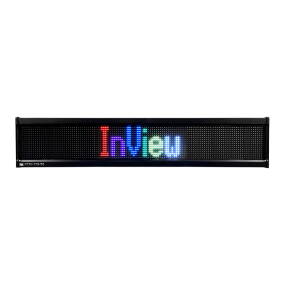
Related Manuals for Spectrum Controls 2706-P4 C2-SC Series


Summary of Contents for Spectrum Controls 2706-P4 C2-SC Series
-
Page 1: Table Of Contents
Description of the InView P42C2-SC and 2706-P44C2-SC Displays Parts List Sign Specifications EMI Compliance Certifications Wiring the 2706-P42C2-SC and 2706-P44C2-SC Displays Mounting the 2706-P42C2-SC and 2706-P44C2-SC Displays 2706-P4xC2 Display Language Messaging Format Codes Additional Resources Getting Technical Assistance PN: 1778600501 Spectrum Controls, Inc. Publication 0100290-01A... -
Page 2: Important User Information
Spectrum Controls, Inc. cannot assume responsibility or liability for actual use based on the examples and diagrams. No patent liability is assumed by Spectrum Controls, Inc. with respect to use of information, circuits, equipment, or software described in this manual. -
Page 3: Overview
Careful cable routing helps minimize electrical noise. Route incoming power to the module by a separate path from the communication cables. Do not run the power and communication wires in the same conduit, or directly next to each other. PN: 1778600501 Spectrum Controls, Inc. Publication 0100267-01B... -
Page 4: Description Of The Inview P42C2-Sc And 2706-P44C2-Sc Displays
The resolution for both displays is 7.6 mm (0.3 in). The displays provide 10, user-selectable colors for fonts and bitmaps. You may scroll images and characters from right-to-left, or left-to-right, depending on the language. The displays comply with NEMA 12 housing standards. Spectrum Controls, Inc. Publication 0100290-01A PN: 1778600501... - Page 5 Installing InView Marquee 2706-P4xC2-SC Message Displays 2706-P42C2-SC Top View 2706-P42C2-SC Rear View with Rear Access Panel Covers Removed 2706-P42C2-SC Bottom View 2706-P44C2-SC Top View 2706-P44C2-SC Rear View with Rear Access Panel Covers Removed PN: 1778600501 Spectrum Controls, Inc. Publication 0100267-01B...
-
Page 6: Parts List
(G)). Alternative Power Entry Point Alternative ½-inch trade size holes (.875- inch) for power wiring with removable watertight plug. (If used replace into rear power entry point (H)). Spectrum Controls, Inc. Publication 0100290-01A PN: 1778600501... -
Page 7: Sign Specifications
UL 60950-1, 2nd Edition Information Technology Equipment – Safety – Part 1: General Requirements • Edition Information Technology Equipment – Safety – Part CSA C22.2 No. 60950-1, 2 1: General Requirements • EN 60950-1:2006/A11:2009/A1:2010/A12:2011/A2:2013 • IEC 60950-1:2005 (Second Edition) + Am 1:2009 + Am 2:2013 PN: 1778600501 Spectrum Controls, Inc. Publication 0100267-01B... -
Page 8: Wiring The 2706-P42C2-Sc And 2706-P44C2-Sc Displays
Use appropriate conduit fittings and connections to route wires for power and communication into the power access compartment. Ensure a provided ferrite is properly installed on the cables as shown in the supplied photos. Spectrum Controls, Inc. Publication 0100290-01A PN: 1778600501... - Page 9 Wire the external power to the rear access power panel as shown. Strip the electrical wires back 6.35 mm (0.25 in), or as needed. Insert the wires into the appropriate terminal connection using the image and table provided. PN: 1778600501 Spectrum Controls, Inc. Publication 0100267-01B...
- Page 10 If the bottom ½ inch trade hole is to be used, remove the watertight hole plug and reinstall it in to the rear ½ inch trade hole. Spectrum Controls, Inc. Publication 0100290-01A PN: 1778600501...
- Page 11 Description EGROUND SHIELD RS485-(A) RS485-(B) 5VDC GROUND RS232TXD RS232RXD GROUND NOTE Only connect one type of communication type to the display at a time. Terminal connection points for communication types are listed below. PN: 1778600501 Spectrum Controls, Inc. Publication 0100267-01B...
- Page 12 To comply with Part 15 of the FCC rules attach one of the provided ferrites around the incoming RS-232 wire(s), and secure with one of the provided tie wraps to the tie wrap anchor. The ferrite must be attached to the sign. Spectrum Controls, Inc. Publication 0100290-01A PN: 1778600501...
- Page 13 The jumper wire (yellow) is not included. For the RS-485 connection, a wire gage between 24 AWG (minimum) and 18 AWG (maximum) is required. Tighten the terminal connection points to a maximum of .056 N-m (5.00 in-lbs). PN: 1778600501 Spectrum Controls, Inc. Publication 0100267-01B...
- Page 14 Module Cable 6010nn-nn Comms Module J1 6: 5VDC RED + 5 V Power J1 Pin 2 7: GND(PWR) BLACK: Supply GND (-5 V) J1 Pin 3 2: Shield Blue Chassis Ground J1 Pin 4 Spectrum Controls, Inc. Publication 0100290-01A PN: 1778600501...
- Page 15 11. The InView User Interface starts up. If you do not have Adobe Flash Player installed on your computer, the software provides a link for you to access, download, and install the Flash Player. Follow Adobe’s instructions to install the Flash Player. PN: 1778600501 Spectrum Controls, Inc. Publication 0100267-01B...
-
Page 16: Mounting The 2706-P42C2-Sc And 2706-P44C2-Sc Displays
Mount the sign so that it is easy to disconnect power when servicing. Always disconnect the communications cable(s) before disconnecting power. Modifying the sign housing voids the warranty. Mounting Displays on a Wall Wall mount brackets dimensions are as follows: Spectrum Controls, Inc. Publication 0100290-01A PN: 1778600501... - Page 17 Attach the two remaining sign brackets to a metal post, wall, ceiling, or other surface with sufficient weight bearing rating. It is preferable that you install the display on metal posts attached directly to studs. Never install the brackets only on sheetrock with toggle bolts. PN: 1778600501 Spectrum Controls, Inc. Publication 0100267-01B...
- Page 18 #10 lock washers (G), and the 4 10-32 lock nuts (H) through the selected alignment holes on each end of the sign. Tighten to 2.71 N-m (24.00 in-lbs). 10. Tighten the two 5/16 nuts (E). See step 5 for reference. Tighten to 2.71 N-m (24 in-lbs). Spectrum Controls, Inc. Publication 0100290-01A PN: 1778600501...
- Page 19 Failure to place the ceiling brackets correctly will result in the sign failing to stay in place when hung from its chains. • A indicates bracket(s). • B indicates bracket screws. PN: 1778600501 Spectrum Controls, Inc. Publication 0100267-01B...
- Page 20 Attach the ceiling mounting brackets (A) to the sign using the 4 6-32×3/8-inch Phillips screws (B) as shown. Tighten to 1.3 N-m (10 in-lbs). NOTE Use chains capable of supporting 4 times the total weight of the signs. Spectrum Controls, Inc. Publication 0100290-01A PN: 1778600501...
-
Page 21: 2706-P4Xc2 Display Language Messaging Format Codes
(00 - FF) for red channel gg=ASCII hex value (00 - FF) for green channel bb=ASCII hex value (00 - FF) for blue channel Character Width/Height Description ASCII Bold ^Q^]01 111D3031 PN: 1778600501 Spectrum Controls, Inc. Publication 0100267-01B... -
Page 22: Additional Resources
In the unlikely event that the display should need to be returned to Spectrum Controls, Inc., please ensure that the unit is enclosed in approved ESD packaging (such as static-shielding/metallized bag or black conductive container). Spectrum Controls, Inc. - Page 23 PN: 1778600501 Spectrum Controls, Inc. Publication 0100290-01A...
- Page 24 ©2019 Spectrum Controls, Inc. All rights reserved. Specifications subject to change without notice. The Encompass logo and ControlLogix are trademarks of Rockwell Automation. Corporate Headquarters Spectrum Controls Inc. 1705 132 Ave NE Bellevue, WA 98005 USA Fax: 425-641-9473 Tel: 425-746-9481 Web Site: www.spectrumcontrols.com...
Need help?
Do you have a question about the 2706-P4 C2-SC Series and is the answer not in the manual?
Questions and answers