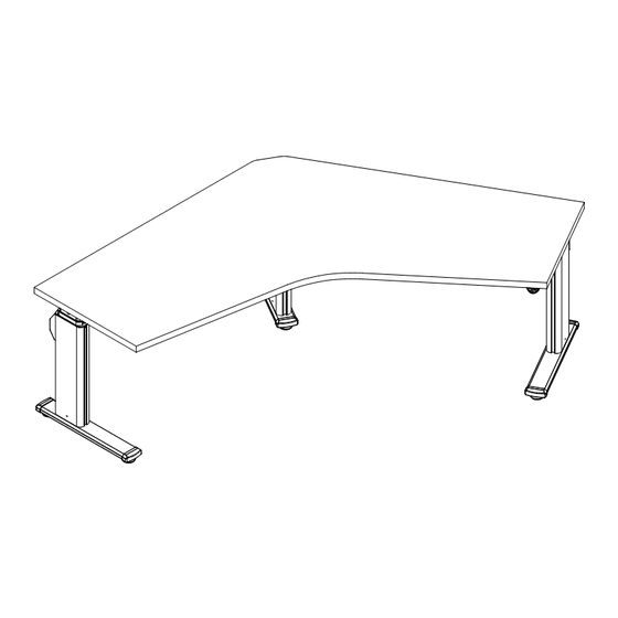
Steelcase 5 Series Manual
Adjustable height tables
Hide thumbs
Also See for 5 Series:
- User manual (6 pages) ,
- Assembly instructions manual (46 pages) ,
- Manual (38 pages)

Subscribe to Our Youtube Channel
Related Manuals for Steelcase 5 Series


Summary of Contents for Steelcase 5 Series
- Page 1 Series 5 Adjustable Height Tables ® 10mm & 14mm 10mm 2.5mm 888.STEELCASE (888.783.3522) www.steelcase.com © 2018 Steelcase Inc. Page 1 of 35 Grand Rapids, MI 49501 U.S.A. 004231D Rev T...
- Page 2 >1" INSPECT REGULARLY. Stop using if product is damaged or has (25mm) loose parts. Only repair with Steelcase authorized parts and methods. MAINTAIN >1” (25mm) GAP ABOVE OBJECTS ON DESK AT MAX HIEGHT AND BETWEEN THE DESK & ADJACENT OBJECTS.
- Page 3 WARNING RISK OF SERIOUS INJURY: POTENTIAL FOR INJURY: The use of worksurfaces that do not comply with the Steelcase defined criteria and limitations could cause personal injury or property damage due to pinch points, instability, or other problems. POTENTIAL FOR NON-COMPLIANCE: The use of work surfaces that do not comply with Steelcase criteria VOIDS any Steelcase claims of compliance with ANSI/BIFMA, UL, LEED, or other applicable requirements.
- Page 4 Illustrations shown here may not match your product. Depending on your region, the plug pin size and shape may change. GROUNDED OPERATING INSTRUCTIONS OUTLET BOX Please refer to the provided User Guide, which is also available at www.steelcase.com Page 4 of 35 Figure 2 004231D Rev T...
- Page 5 ® Parts Provided DRIVESHAFT PKG: 9506000 09~34 DRIVESHAFT PKG: 9506000 09~34 Page 5 of 35 004231D Rev T...
-
Page 6: Table Of Contents
® TABLE OF CONTENTS: PAGE(S): Lets Get Started!......................Which Legs Go Where?....................Determine Leg Positions on your Table..............Overhangs and Custom Leg Positions............... Mounting Legs to Worksurfaces................. Determine Switch Position on your Table..............Corner Tables....................... Left-Hand Tables......................For 90 Tables......................For 120 Tables...................... -
Page 7: Lets Get Started
® Let’s Get Started Assembling a monitor-keyboard worksurface with Prepare a large open space to assemble the table. a bi-level mechanism? Jump to Appendix 'B' now. • Sweep the floor! Screws and small parts can damage the worksurface. • Put down a CLEAN shipping blanket to protect the worksurface. Unpack the worksurface and place on the shipping blanket upside-down. -
Page 8: Which Legs Go Where
® Which Legs Go Where? Leg Types: NOTE: Extra studs. NOTE: Extra studs. 10" Standard 21" Standard 26" Standard 10" Corner 21" Corner 26" Std. 21" Std. 26" Std. 26" Std. 21" Std. 21" Std. 23"D Rectangle 29"D Rectangle Concave Taper-Flat 40"... -
Page 9: Determine Leg Positions On Your Table
® Overhangs and Custom Leg Positions: Determine Leg Positions on your Table: • Many Series 5 tables allow multiple leg postions, providing flexibility to • There are pilot holes in worksurfaces that result in the standard maximize leg space, and allow overhangs for CPU slings and mobile overhangs (1-1/4"... -
Page 10: Mounting Legs To Worksurfaces
® Mounting Legs to Worksurfaces CAUTION: All holes in the leg mounting plates MUST be filled with screws. Failure to install all screws may result in structural instability. NOTCH IS ALWAYS Worksurface AT BACK OF LEG Mounting Plate (BACK OF TABLE) Pilot Holes = PILOT HOLE = NO PILOT HOLE PROVIDED... -
Page 11: Determine Switch Position On Your Table
® Determine Switch Position on your Table: • The switch can be located on either side of your table, but the switch comes with a short cable to minimize clutter. So, be sure to always locate the primary motor near the switch location. NOTE: It does not matter which side of the table the primary or secondary motor goes on. -
Page 12: 90 O Corner Tables
Corner Tables ® corner tables are available either as right-hand or left-hand tables. In order to go from right-hand to left-hand configurations, three (3) items must be changed: 1) Orientation of center leg 2) Placement of stretchers 3) Configuration of intermediate gearbox (See page 10) The gearboxes ship from the factory set up for right-hand tables. -
Page 13: Left-Hand Tables
Left-Hand Tables ® INTERMEDIATE GEARBOX NOTE: Switch & primary motor can still be placed on either right-hand or left-hand side, regardless of whether it is a left-hand or right-hand table. SHORT SIDE ON RIGHT LONG SIDE ON LEFT "B" FACES IN CENTER LEG SPECIAL STRETCHER... -
Page 14: For 90 O Tables
® For 90 o Tables For 120 o Tables Attach the intermediate gearbox to the center leg using the In the center leg, insert the short (4") driveshaft, hardware provided. Refer to note below and use spacer and and attach a universal joint to each end. Tighten 30 mm bolt as required. -
Page 15: Identify The Primary And Secondary Motors
® Identify the Primary and Secondary Motors Rear View Primary Secondary Secondary The primary motor and secondary motor look the same, except for the connection panel at the back. Primary NOTE: The power supply converts 120V AC from the wall outlet to 24V DC. The series 5 motors operate on 24V DC. -
Page 16: Installing Motors And Synchronizing Legs
Installing Motors and Synchronizing Legs ® Driveshafts and Leg Synchronization Secondary Motor Series 5 legs and motors must be synchronized before installing the driveshafts. Determine on which side of the table each motor will go. (see page 8) Series 5 motors are shipped from the factory in the Install M6 x 80 bolts &... -
Page 17: Installing Driveshafts
Installing Driveshafts ® Note: Set screw must be loosened slightly If the hexagon openings are not perfectly aligned, grip to allow insertion of shaft. Set screw to be the driveshaft with an adjustable wrench and rotate tightened very tightly after all shafts are in slightly, until the driveshaft slides through with ease. - Page 18 Installing Driveshafts (cont.) ® 2-Leg Tables: 2-Leg Tables & 120 Tables Driveshafts are retained using cap nuts, which grip the driveshaft ends and prevent them from backing out of the legs. 120 o Tables: 2-leg tables & 120 tables require one cap nut mounted outside of each leg.
- Page 19 Installing Driveshafts (cont.) ® Steps 4, 5, & 6 (below) are for 90 Tables. With all table legs pushed all the way down, Using a adjustable wrench or pliers to assist, push the insert driveshafts through gearboxes and legs. push nut all the way down the length of the driveshaft until it meets the inside of the lifting column.
-
Page 20: Through
® Installing Driveshafts (cont.) Tighten the motor mounting nuts. Reinstall motor. MOUNTING SCREWS Ensure all driveshafts are inserted into driveshaft tubes. The alignment of the (2) inner hexagonal driveshafts and the Tighten set screws very tightly with 3mm hex wrench. (1) outer driveshaft / collar needs to be as straight as possible. -
Page 21: Installing Switch & Power Supply
Installing Switch & Power Supply ® POWER SUPPLY NOTE: Mount the power supply in a way that assures accessories can be clamped to the 90º: worksurface, and allow all cables to reach. POWER SUPPLY 120º: POWER SUPPLY Straight: Mount and install the power supply with two (2) of the Attach the switch at the front of the worksurface, adjacent to #10 x 1.075 long screws provided. -
Page 22: Attach Driveshaft Covers And Wire Managers
® Attach Driveshaft Covers and Wire Managers LONG COVER SHORT COVER NOTE: There should be about 1/4" between the motors and the driveshaft covers. Determine which driveshaft cover goes where, if applicable. Attach driveshaft covers using four (4) screws each, into the pre-drilled pilot holes. 1/4"... -
Page 23: Installing Stretchers
Installing Stretchers ® NOTE: On 3-leg tables, be sure to use the correct length of stretcher for the particular side of the worksurface. Use longer components on the long side and shorter components on the short side, where applicable. Sub-assemble stretchers as shown. For 90 stretcher, place the decorative cover over the small tube first, then insert into large tube. -
Page 24: Installing Stretchers
Installing Stretchers (cont.) ® tables, mount the center leg bracket as Gently tighten all set screws between stretcher tubes. shown such that the set screws face the floor. Add decorative cover after tightening the two (2) M6 nuts. SET SCREWS TO FACE THE FLOOR. -
Page 25: Connect And Route All Cables
® Connect and Route All Cables Connect power supply to primary motor with the cable already attached to the power supply. Connect switch to primary motor using the supplied RJ-11 cable. NOTE: To manage switch cable, and to prevent damage to the connection point on the motor, use the supplied cable clips as shown. -
Page 26: Finishing The Table Assembly
Finishing the Table Assembly ® PLEASE LEAVE THESE INSTRUCTIONS, AND THE USER GUIDE, IN AN OBVIOUS PLACE Ensure all decorative trim caps are securely attached. FOR THE END USER AFTER ASSEMBLY. Double-check that all nuts, bolts, screws and compression nuts are securely attached. STRETCHER CAPS Finally, adjust glides to level the table, both left to right and front to back. -
Page 27: Appendix A: 2-Piece Worksurface Assembly
Appendix A: 2-Piece Worksurface Assembly ® Position top pieces upside down on the assembly surface and align with wood spline (or biscuits) provided. Optional Biscuits SPLINE Install draw bolts and tighten with 5/16" or 7/16" open end wrench. Attach three (3) v-channels using sixteen (16) screws DRAW per channel. - Page 28 Appendix A: 2-Piece Worksurface Assembly (cont.) ® Special Notes on 2-Piece Worksurfaces Overhangs: • The extension portion of 2-piece worksurfaces may not completely overhang the supporting leg! • One leg must always be fully mounted to the extension portion. CORRECT! CORRECT! WRONG! THIS CONDITION...
-
Page 29: Appendix B: Installing A Keyboard Mechanism For Bi-Level Worksurfaces
Appendix B: Installing a Keyboard ® Mechanism for Bi-Level Worksurfaces Prepare a large open space to assemble the table. • Sweep the floor! Screws and small parts can damage the worksurface. • Put down a CLEAN shipping blanket to protect the worksurface. Unpack the worksurface and place on the shipping blanket upside-down. - Page 30 Appendix B: Installing a Keyboard ® Mechanism for Bi-Level Worksurfaces (cont.) Lower keyboard mechanism onto underside Attach small spacer plate next to the arm attached to the piston. of work surface as shown. Align with pilot The spacer limits the travel of the mechanism to prevent holes on both portions of work surface.
- Page 31 Appendix B: Installing a Keyboard ® Mechanism for Bi-Level Worksurfaces (cont.) NOTE: The pneumatic piston is pre-set at the factory for level installation (monitor and keyboard portion of worksurface in same horizontal plane). From this position, the piston must extend and compress, to allow the full range of motion of the mechanism.
- Page 32 Appendix B: Installing a Keyboard ® Mechanism for Bi-Level Worksurfaces (cont.) Remove circlip from piston (7a) and remove piston from bracket. Assemble nut to threaded end of pneumatic piston (7b). Screw nut all the way down on the threads from the end (7c). CIRCLIP PNEUMATIC PISTON...
- Page 33 Appendix B: Installing a Keyboard ® Mechanism for Bi-Level Worksurfaces (cont.) Align threaded hole in plastic actuator with threads on piston (10a), and screw piston into place (10b). NOTE: There should be about 3/8" of throw in the lever when asssembled correctly (10c).
- Page 34 Appendix B: Installing a Keyboard ® Mechanism for Bi-Level Worksurfaces (cont.) Align mounting plate for actuator with pilot holes in keyboard portion of worksurface and install with two (2) screws. MOUNTING PLATE Place end of actuator cable in slot on underside of handle (13a). Turn handle over, align guide hooks with rails on mounting plate and slide handle over mounting plate (13b).
-
Page 35: Through
Appendix B: Installing a Keyboard ® Mechanism for Bi-Level Worksurfaces (cont.) For Compression Nut Version: NOTE: For 90 small-corner bi-level tables with 2-leg base only. The cosmetic caps that cover the ends of the driveshafts are not used and may be discarded. Rectangular Bi-Levels: Motor Placement on Rectangular Bi-Level ACTUATOR...
Need help?
Do you have a question about the 5 Series and is the answer not in the manual?
Questions and answers