Advertisement
Quick Links
Steelcase, Inc.
Grand Rapids, MI 49501
U.S.A.
1-888-783-3522
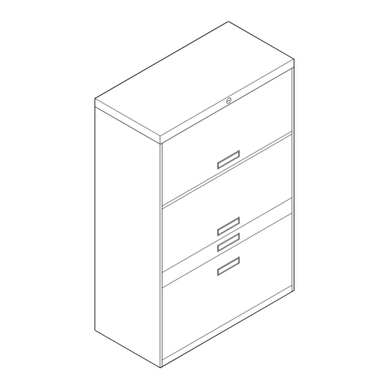
800/900 Series Field Installed Lock Package
Tools
Assembly Directions
Assembly Directions
Consignes de montage
Instrucciones para el ensamblaje
Lock Package Includes:
2
Lock Bars LH & RH
1
Lock Box Assembly
1
Lock Rod
Varies
Lock Catch LH & RH
2
Lock Rod Support LH & RH
Varies
Screw #8 X 3/8 T.H., P.H., Type AB
2
Springs
Varies
Lock Bar Retainer LH & RH
NOTE: These directions apply to cases manufactured after
April 16, 1979. The keying of these locks is the same as desk
locks FR-301 through FR-450. If your file has sliding doors,
special lock catches and lock bar retainers are required.
Order from Steelcase Customer Service.
Printed In U.S.A.
Printed In U.S.A.
Imprime aux Etats-Unis d'Amerique
Impreso en EE.UU.
REV
93-9500951 B
Page 1 of 10
Advertisement

Related Manuals for Steelcase 800 Series


Summary of Contents for Steelcase 800 Series
- Page 1 April 16, 1979. The keying of these locks is the same as desk locks FR-301 through FR-450. If your file has sliding doors, special lock catches and lock bar retainers are required. Order from Steelcase Customer Service. Tools Assembly Directions Assembly Directions Printed In U.S.A.
- Page 2 Mark each interior and corresponding opening with a piece of tape on the front and inside of the case. This tape is necessary when installing lock catches for proper height interiors. 15" High Fixed Shelves with Door 48" Interior 15" High Fixed Shelves with Door 3"...
- Page 3 Drawer Removal Assembly Directions Page 93-9500951 REV B 3 of 10...
- Page 4 Door Removal Inside view Assembly Directions Page 93-9500951 REV B 4 of 10...
- Page 5 Carefully remove knock-out in center of case top by using a punch and hammer. After slug is removed file any small burrs that may be on edges of hole with small round file. Install lock bar into recess of front upright with rectangular slot to the front. Attach spring to hole in recess of front of fourth square cut-out from the bottom of the front upright.
- Page 6 Slide left and right hand lock rod supports on to each end of lock rod with identification mark at left rear. IMPORTANT: Identification Mark at Rear and Left Left and Right Hand Lock Rod Support Assembly Directions Page 93-9500951 REV B 6 of 10...
- Page 7 Move lock rod to locked position and insert attaching screw. Insert left hand lock rod support using the same procedures. Use Steelcase Brush Lube Here Right Hand Lock...
- Page 8 Top of Case Identification mark at rear left Lock Yoke Lock Rod Lock Push Tabs Over Lock Rod Note: Lubricate all friction points with Steelcase Brush Lube (lock yoke and top of tabs). Assembly Directions Page 93-9500951 REV B 8 of 10...
- Page 9 Refer to Step 1 for location of lock catches. Install second from bottom catches first. To accomplish this, slide lock catches through rectangular slot in lock bar and attach with round head screws 3/8" long (provided with lock package). Remove tape. Lock Catch Lock Bar For File without Sliding Doors...
- Page 10 Drawer Replacement Door Replacement Push door in completely. Inside View Assembly Directions Page 93-9500951 REV B 10 of 10...
Need help?
Do you have a question about the 800 Series and is the answer not in the manual?
Questions and answers