
Subscribe to Our Youtube Channel
Related Manuals for DMP Electronics 7000INT Series


Summary of Contents for DMP Electronics 7000INT Series
- Page 1 7000INT Series International Thinline Keypad INSTALLATION AND PROGRAMMING GUIDE F R I 2 : 52 PM...
-
Page 3: Table Of Contents
TABLE OF CONTENTS About the Keypad ......1 Mount the Keypad ......11 7060-WINT .............1 Tamper Protection ..........11 7063-WINT .............1 Program the Keypad ....13 7073-WINT .............1 Keypad Options ...........13 Custom Card Format Keypad Features ......2 ......18 Additional Programming ......... 24 Enter Characters ...... - Page 4 Wiring Specifications....29 Keypad Specifications ....30 Public Card Formats ....31 Readers and Credentials .... 32 Compliance Specifications ..34 Specifications ............34 Compatibility ............34 What Is Included? ..........34 Accessories............34 International Certifications ..35 Security Grade 3 ..........35 Environment Class II .........
-
Page 5: About The Keypad
Four fully-programmable Class B, Style A, supervised, power limited protection zones that can be programmed for a variety of burglary and access control applications. Digital Monitoring Products, Inc | 7000INT Series Installation and Programming Guide... -
Page 6: Keypad Features
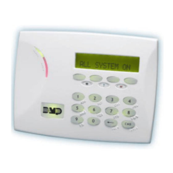
Armed/Power Status List LEDs F R I 2 : 52 PM Panic Keys Proximity Credential Reader Command and Backlit Logo (CMD) Key Back Arrow Key Figure 1: Keypad Features 7000INT Series Installation and Programming Guide | Digital Monitoring Products, Inc. -
Page 7: Enter Characters
Υ Φ Χ Ψ Ω Space Space Space Space . ‘ * < # > . ‘ * < # > Table 2: Latin Characters Table 1: Greek Characters Digital Monitoring Products, Inc | 7000INT Series Installation and Programming Guide... -
Page 8: Install The Keypad
Repeat with the other slot. Gently separate the cover from the base and set the cover containing the keypad components aside. See Figure 2. Figure 2: Separate the Keypad Housing 7000INT Series Installation and Programming Guide | Digital Monitoring Products, Inc. -
Page 9: Wire The Keypad
1-4. Connect the red wire to panel terminal 7, connect the yellow wire to panel terminal 8, connect green wire to panel terminal 9, and connect black wire to panel terminal 10. Digital Monitoring Products, Inc | 7000INT Series Installation and Programming Guide... - Page 10 100 Ohms. Ground fault detected at 1420 Ohms or less. Black – Ground Green – Receive Data All Keypads Yellow – Send Data Red – Keypad Power Figure 3: Keypad Back Showing Wiring Assignments 7000INT Series Installation and Programming Guide | Digital Monitoring Products, Inc.
-
Page 11: Wire For Access Control
Connect the reader (Data 1) wire to the white wire on the 5–wire keypad cable. Connect the reader (Data 0) wire to the green/white wire on the 5–wire keypad cable. See Figure 4. Digital Monitoring Products, Inc | 7000INT Series Installation and Programming Guide... - Page 12 (7/0 Panic) Black – Ground Green – Receive Data Yellow – Send Data Red – Keypad Power External Card Reader To Panel Keypad Bus Figure 4: Access Control Wiring 7000INT Series Installation and Programming Guide | Digital Monitoring Products, Inc.
-
Page 13: Wire The Electronic Lock
NO and C terminals. Conversely, if the device is connected to the NC and C terminals, install the 333 Suppressor on NC and C terminals. See Figures 5a and 5b. Digital Monitoring Products, Inc | 7000INT Series Installation and Programming Guide... - Page 14 Model 333 Magnetic Door Lock Supressor Normally Open Figure 5a: Typical Magnetic Lock Wiring – Power Supply Model 333 Door Strike Relay Supressor Figure 5b: Typical Door Strike Wiring 7000INT Series Installation and Programming Guide | Digital Monitoring Products, Inc.
-
Page 15: Mount The Keypad
Place the keypad cover back onto the base and snap into place. Note: All DMP keypad housings are designed to install on any 4” square box, 3-gang switch box, DMP 695 and 696 back-box, or a flat surface. Digital Monitoring Products, Inc | 7000INT Series Installation and Programming Guide... - Page 16 Surface and Backbox Tamper Puck Mounting Holes Figure 6: Tamper Protection Combined 4-Square and Gang Switch Box Mounting Holes 7000INT Series Installation and Programming Guide | Digital Monitoring Products, Inc.
-
Page 17: Program The Keypad
CMD. Do not enter a leading zero for addresses 01 to 09. Digital Monitoring Products, Inc | 7000INT Series Installation and Programming Guide... - Page 18 (emergency), and FI (fire). Press the select key again to disable the panic option. Once the panic option is enabled, an asterisk displays next to the selected option(s). Press CMD. 7000INT Series Installation and Programming Guide | Digital Monitoring Products, Inc.
- Page 19 If the zone does not restore before the programmed time, the keypad ends the bypass and indicates the open or short zone condition to the panel. Digital Monitoring Products, Inc | 7000INT Series Installation and Programming Guide...
- Page 20 Time). During this time, the user can open the protected door to start the programmed Zone 2 bypass entry/exit timer. After the programmed number of seconds, the relay restores the door to its locked state. 7000INT Series Installation and Programming Guide | Digital Monitoring Products, Inc.
- Page 21 YES or AWAY. Select zero (0) to disable this feature. The delay also occurs when a credential is presented for arming the H/S/A system. Default is 2. Digital Monitoring Products, Inc | 7000INT Series Installation and Programming Guide...
-
Page 22: Custom Card Format
Please contact the credential supplier or manufacturer for the bit structure. Press CMD to advance. Format Name FORMAT NAME Press any select key to rename the card format. Press CMD *UNUSED* to save and advance. 7000INT Series Installation and Programming Guide | Digital Monitoring Products, Inc. - Page 23 Length = 8 Length = 16 Position = 25 Position = 0 In this example the Wiegand Code Length = 26 bits. Figure 7: Wiegand Data Stream Bit Location Digital Monitoring Products, Inc | 7000INT Series Installation and Programming Guide...
- Page 24 In addition to user code verification, door access is only granted when any one site code programmed at the SITE CODE option matches the site code received in the Wiegand string. 7000INT Series Installation and Programming Guide | Digital Monitoring Products, Inc.
- Page 25 OFF does not affect any REX operation. If communication is lost during a door strike, the relay remains on for the door strike duration but turns off at the end of the door strike timer. Digital Monitoring Products, Inc | 7000INT Series Installation and Programming Guide...
- Page 26 Press the first select key to choose LAST (Keep Last State). NO COMM WITH PNL The relay remains in the same state and does not change LAST when communication is lost. 7000INT Series Installation and Programming Guide | Digital Monitoring Products, Inc.
- Page 27 4 to select Dutch. Press CMD to advance the language options. Press select key 1 to select Greek. Press select key 2 to select KYPD LANGUAGE: Czech. EΛΛ CZK Digital Monitoring Products, Inc | 7000INT Series Installation and Programming Guide...
-
Page 28: Additional Programming
Press any select key. Choose ADD. At ENTER CODE: -, present the credential to the reader. The keypad works by reading the user code from the data string sent by the access control reader. 7000INT Series Installation and Programming Guide | Digital Monitoring Products, Inc. -
Page 29: Test The Keypad
Press and hold each key for two seconds. The key number being held appears in the display. Verify the correct number displays before testing the next key. Digital Monitoring Products, Inc | 7000INT Series Installation and Programming Guide... - Page 30 Test the Credential Reader INPUT WIEGAND This option tests the internal and external reader input from proximity credentials. The display shows OKAY each time a good proximity read is received. 7000INT Series Installation and Programming Guide | Digital Monitoring Products, Inc.
-
Page 31: Arm And Disarm The System
If disarming, select DISARM. At ENTER CODE: -, enter a user code at the keypad or present a credential to the proximity reader. Digital Monitoring Products, Inc | 7000INT Series Installation and Programming Guide... -
Page 32: Home/Sleep/Away System Type
Once validated, the system disarms all areas accessible by the credential and activates the Door Strike Relay. Area systems provide a delay to allow selected areas only to be disarmed. See Figure 9. Figure 9: Entry Delay 7000INT Series Installation and Programming Guide | Digital Monitoring Products, Inc. -
Page 33: Wiring Specifications
2 VDC. If the voltage at any device is less than the required level, add an auxiliary power supply at the end of the circuit. When voltage is too low, the devices cannot operate properly. Digital Monitoring Products, Inc | 7000INT Series Installation and Programming Guide... -
Page 34: Keypad Specifications
ALARM CURRENT PROX BY CURRENT ZONES INPUT STRIKE READER RELAY 7060INT 72 mA 87 mA 7063INT 85 mA 100 mA 100 mA+2 mA 85 mA+1.6 mA 7073INT per active zone per active zone Table 3: Keypad Specifications 7000INT Series Installation and Programming Guide | Digital Monitoring Products, Inc. -
Page 35: Public Card Formats
LENGTH POSITION LENGTH POSITION LENGTH DIGITS H10301 26 BIT H10302 37 BIT W/FAC H10304 37 BIT W/O FAC FARPOINTE 39 BIT CORPORATE 1000 35 BIT CORPORATE 1000 48 BIT Digital Monitoring Products, Inc | 7000INT Series Installation and Programming Guide... -
Page 36: Readers And Credentials
1346 PROXKEY III® PROXIMITY READER ACCESS DEVICE PP-5355 PROXPRO PROXIMITY 1351 PROXPASS® READER WITH KEYPAD PR-5455 PROXPRO® II PROXIMITY 1386 ISOPROX II® CARD READER TL-5395 THINLINE II® PROXIMITY READER 7000INT Series Installation and Programming Guide | Digital Monitoring Products, Inc. - Page 37 FARPOINTE CLAMSHELL READER SMARTCARD DELTA5 FARPOINTE SMARTCARD DM1-3 FARPOINTE IMAGEABLE READER SMARTCARD DELTA5.3 FARPOINTE SMARTCARD FARPOINTE MIFARE® READER DESFIRE® EV1 SMARTCARD DELTA6.4 FARPOINTE SMARTCARD READER DK1-3 FARPOINTE KEY FOB SMARTCARD Digital Monitoring Products, Inc | 7000INT Series Installation and Programming Guide...
-
Page 38: Compliance Specifications
• XT30INT Series Panels • XR150INT/XR550INT Series Panels What Is Included? • One LCD Keypad • One Model 333 Suppressor Accessories 695 or 696 Keypad Backbox, 777 protective keypad cover 7000INT Series Installation and Programming Guide | Digital Monitoring Products, Inc. -
Page 39: International Certifications
EN 60839-11-1:2013 Alarm and electronic security systems. Electronic access control systems. System and components requirements. EN 61000-3-2:2006+A1+A2 Electronic compatibility (EMC)–Part 3-2: Limits – Limits for harmonic current emissions. Digital Monitoring Products, Inc | 7000INT Series Installation and Programming Guide... - Page 40 <16 A per phase and not subject to conditional connection. EN 61000-6-4:2007 Emission standard for industrial environments. Information furnished is believed to be accurate and reliable. This information is subject to change without notice. 7000INT Series Installation and Programming Guide | Digital Monitoring Products, Inc.
- Page 44 LT-0883INT 19081 1.01 © 2019 Digital Monitoring Products, Inc.
Need help?
Do you have a question about the 7000INT Series and is the answer not in the manual?
Questions and answers