DMP Electronics Thinline Aqualite 7000 Series Installation And Programming Manual
Hide thumbs
Also See for Thinline Aqualite 7000 Series:
- Installation sheet (11 pages) ,
- Installation and programming manual (24 pages)

Related Manuals for DMP Electronics Thinline Aqualite 7000 Series


Summary of Contents for DMP Electronics Thinline Aqualite 7000 Series
- Page 1 7000 Series Thinline Aqualite Keypad INSTALLATION AND PROGRAMMING GUIDE F R I 2 : 52 PM...
-
Page 3: Table Of Contents
TABLE OF CONTENTS About the Keypad ......1 Test the Keypad ......28 Keypad Features ......2 End User Training ....... 30 Keypad Arming and Disarming .....31 Enter Characters ......4 Keypad Access Control ........33 Number Pad ............4 Keypad Entry Delay .......... 34 Panic Key Options .......... -
Page 5: About The Keypad
ABOUT THE KEYPAD Thinline Series (7060, 7063, 7070, 7073, 7160, 7163, 7170, and 7173) and Aqualite Series (7060A, 7063A, 7070A, and 7073A) LCD keypads offer flexible features and functionality. Each keypad provides: • Custom 16-character home or business name in the display •... -
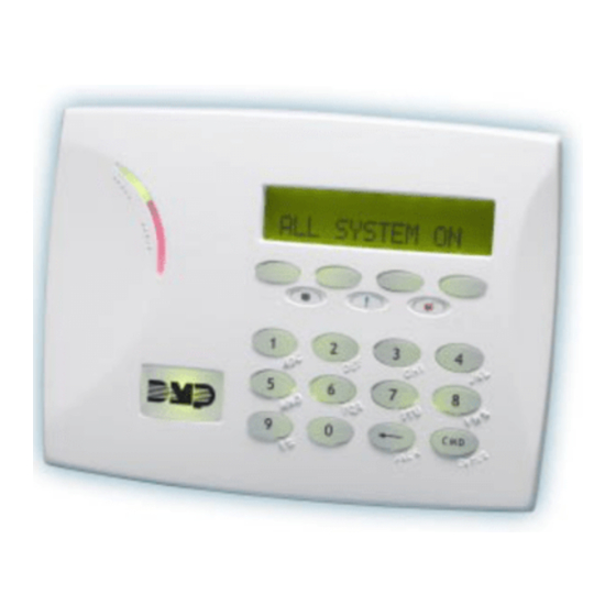
Page 6: Keypad Features
KEYPAD FEATURES Select Keys Keypad Display/ Armed/Power Status List LEDs F R I 2 : 52 PM Panic Keys Proximity Credential Reader Command and Backlit Logo (CMD) Key Back Arrow Key Figure 1: 7000 Series LCD Keypad Digital Monitoring Products, Inc | 7000 Series Installation and Programming Guide... - Page 7 32-Character Display Power LED ABC SECURITY Select Keys F R I 2 : 52 PM Armed LED Proximity Command Credential Reader and Backlit Logo Back Arrow Figure 2: Thinline 7100 Series LCD Keypad 7000 Series Installation and Programming Guide | Digital Monitoring Products, Inc.
-
Page 8: Enter Characters
ENTER CHARACTERS NUMBER PAD Choose a character from the table. Use the Greek Characters table if Greek was selected as the keypad language setting. Identify the Number the character correlates with and press that number on the number pad. Identify the Select Key for the character and press that select key on the keypad. Press that select key again for the lowercase letter (Latin characters only). -
Page 9: Panic Key Options
PANIC KEY OPTIONS 2-Button Panic Keys All keypads offer a panic key function that allows users to send panic, emergency, or fire reports to the central station in an emergency. Enable the panic key function in the keypad user menu. Place the supplied icon stickers below the top row select keys. The user must press and hold the two select keys for two seconds until a beep is heard. -
Page 10: User Options Menu
USER OPTIONS MENU To access the Options menu, press and hold the back arrow and CMD keys for 2 seconds. Backlighting Brightness Adjust the LCD display brightness level, power and armed LEDs, the green keyboard, and the logo backlighting. At SET BRIGHTNESS, use the left select key to decrease the brightness and the right select key to increase the brightness. -
Page 11: Install The Keypad
INSTALL THE KEYPAD REMOVE THE COVER The keypad housing is made up of two parts: the cover, which contains the circuit board and components, and Cover the base. To separate the keypad cover from the base, insert a flathead screwdriver into one of the slots on the bottom Base of the keypad and gently lift the screwdriver upward. -
Page 12: Wire The Keypad
WIRE THE KEYPAD Each keypad model has specific wiring assignments. All zones are supervised. Use 1k Ohm EOL resistors, DMP Model 311 on keypad zones 1-4. Locate the keypad model below and refer to Figure 5 to wire the keypad. Models 7060/A, 7063/A, 7160, and 7163 Supplied with a 4-wire harness for panel keypad bus connection. - Page 13 Additional Power Supply If the current draw for all keypads exceeds the panel output, provide additional current by adding a Model 505-12 auxiliary power supply. Connect all keypad black ground wires to the power supply negative terminal. Run a jumper wire from the power supply negative terminal to the panel common ground terminal.
- Page 14 Surface and Backbox Mounting Holes Green/White – Connect Reader Data 0 White – Connect Reader Data 1 ExternalReader/Door Strike Orange – Door Strike N/O 7073/7073A, 7173 Keypads – Gray Door Strike C – Violet Door Strike N/C Yellow/White 1K EOL –...
-
Page 15: Wire For Access Control
WIRE FOR ACCESS CONTROL Internal Access Control Reader The 7063/A, 7073/A, 7163, and 7173 keypads provide a built-in proximity card reader that is compatible with most standard 125 kHz proximity credentials. An external 13.56 MHz proximity reader can be connected and will be compatible with 13.56 MHz proximity credentials. - Page 16 Green/White* - Connect Reader Data 0 White - Connect Reader Data 1 Orange - Door Strike Normally Open Gray - Door Strike Common Violet - Door Strike Normally Closed – Yellow & White 1K EOL Zone 4 *Only the green/white, –...
-
Page 17: Wire The Electronic Lock
WIRE THE ELECTRONIC LOCK The 7073/A and 7173 keypads provide one internal programmable Form C single pole, double throw (SPDT) relay for controlling door strikes or magnetic locks. Three wires on the 5-wire harness, violet normally closed (N/C), gray common (COM), and orange normally open (N/O), allow you to connect devices to the relay. - Page 18 Green/White – D0 White – D1 Orange – N/O Gray – C Violet – N/C Model 333 Supressor Keypad 5-Wire Harness – DMP 505 Power Supply Magnetic Door Lock Figure 7: 5-Wire Harness and 333 Suppressor Installation Digital Monitoring Products, Inc | 7000 Series Installation and Programming Guide...
- Page 19 Door Strike Relay Operation When the user code sent from the reader is verified by the panel, the keypad door strike relay activates for five seconds. During this time, the access door connected to Zone 2 must be opened to start the programmed entry/exit timer and Zone Bypass if programmed and used.
-
Page 20: Program The Keypad
PROGRAM THE KEYPAD Keypad Options and Keypad Diagnostic menus allow install and service technicians to configure and test keypad operation. To access the installer options: Hold down the back arrow and CMD keys for two seconds. At SET BRIGHTNESS, enter 3577 (INST) and press CMD. The display changes to KPD OPT KPD DIAG and STOP. - Page 21 Keypad Mode KEYPAD MODE: Keypads with programmed zones must be supervised and *SUP UNSUP cannot share an address with other keypads. Unsupervised keypads can operate together sharing the same address, but cannot be used when Device Fail Output has a programmed value other than zero.
- Page 22 Activate Zone 2 Bypass (7073/A, 7173 only) ACTIVATE ZONE 2 Select YES to activate the zone 2 bypass operation. BYPASS? Selecting NO allows standard zone operation on zone 2. The default is NO. Zone 2 Bypass Time (7073/A, 7173 only) ZONE 2 BYPASS Enter the number of bypass seconds to elapse before the TIME:...
- Page 23 Activate Zone 3 Exit (7073/A, 7173) ACTIVATE ZONE 3 Select YES to enable the Request to Exit feature on zone EXIT: NO 3. When zone 3 shorts, the keypad relay activates. During this time, the user can open the protected door to start the programmed bypass entry/exit timer.
-
Page 24: Custom Card Format
CUSTOM CARD FORMAT Note: Custom card format programming options are only available on 7063/A, 7073/A, 7163, and 7173 keypads. Card Formats CARD FORMATS Select DMP to allow credentials that use a 26-45 bit data DMP CUSTOM string. The menu advances to REQUIRE SITE. Select CUSTOM to disable DMP format and program slots 1-8 as needed. - Page 25 Card Format Number CARD FORMATS Select the slot number (1-8) that you want to program FORMAT NO: for a custom non-DMP card format. The format that is programmed into slot 1 is the default format. In the event that a card with an unrecognized format is used, that card will be read in the format that is programmed in slot 1.
- Page 26 Format Name FORMAT NAME Press any select area to rename the card format. Press CMD *UNUSED* to save and advance. Wiegand Code Length WIEGAND CODE When using a custom credential, enter the total number of LENGTH: bits to be received in Wiegand code including parity bits. Press any select key or area to enter a number between 1-255 to equal the number of bits.
- Page 27 Site Code Position and Length SITE CODE Enter the site code start position and length in the data POS: 1 LEN: 8 string. Press select area 2 to clear the site code start position and enter a number between 0-255. Press CMD to save. Default is 1.
- Page 28 Site Code Display SITE CODE 1: You can program up to eight 8-digit site codes. The site code range is 0-16,777,214. In the keypad display, enter site code 1 and press CMD. The display will ask for site code 2 followed by site code 3 and so on.
- Page 29 No Communication with Panel NO COMM WITH PNL Define the relay action when communication with the panel OFF SITE ANY ON has not occurred for 5 seconds. Default is OFF. Press any select key or area to change the default relay action: Press the first select key or area to choose OFF (Relay Always Off).
- Page 30 Keypad Language KYPD LANGUAGE: Define the keypad’s language. Default is ENGLSH. LANG: ENGLSH Press any select key to change the language options. Press select key 1 to select English. Press select key 2 to KYPD LANGUAGE: select Spanish. Press select key 3 to select French. Press ENG SPN FRN DUT select key 4 to select Dutch.
-
Page 31: Additional Programming
ADDITIONAL PROGRAMMING Users can manually enter their user code into the keypad which then verifies the user code and its authority with the panel. The 7073/A and 7173 activate the on-board Form C relay releasing a door strike or magnetic lock. To provide added flexibility, the keypad allows connection of an external Wiegand output compatible reader. -
Page 32: Test The Keypad
TEST THE KEYPAD Test the keypad to ensure alarm backlighting, individual shortcut keys, and any programmed zones work. To begin testing, access the Installer Options menu. Hold down the back arrow and CMD keys at the same time until SET BRIGHTNESS displays. Enter 3577 and press CMD. - Page 33 Zone Test (7070, 7073/A, 7170, 7173) Z1 OPEN Z2 OPEN This option allows the keypads to display the current Z3 OPEN Z4 OPEN electrical status of the four protection zones. The status is shown as OPEN, SHRT, or OKAY. The zone test displays on the other keypads but is not operational.
-
Page 34: End User Training
END USER TRAINING This section covers 7063/A, 7073/A, 7163, and 7173 keypads and contains three sections: • Keypad Arming and Disarming • Keypad Access Control • Keypad Entry Delay All of the examples displayed assume that CLOSING CODE is YES in panel programming. Figures 9 through 12 show the user presenting a card to the keypad. -
Page 35: Keypad Arming And Disarming
KEYPAD ARMING AND DISARMING Area System Arming and Disarming Press CMD until the keypad displays ARM DISARM. Press the select key under the preferred option. The keypad displays ENTER CODE: -. The user presents their card to the reader. Once validated by the system, all areas assigned to that code arm or disarm automatically and the 7073/A and 7173 keypad door strike relay activates. - Page 36 All/Perimeter System Arming and Disarming Present the card to the reader or press CMD, the keypad displays DISARM? or PERIM ALL (when arming). Press the select key under the desired option. The keypad displays ENTER CODE: -. Present the card to the reader. Once validated by the system, the selected areas arm or disarm automatically.
-
Page 37: Keypad Access Control
KEYPAD ACCESS CONTROL Area and All/Perimeter Door Strike From the Status List, present your card to the reader. Once the system validates the card, the Door Strike relay activates. Home/Away systems only activate the 7073/A, and 7173 Door Strike relay when arming and disarming. ABC SECURITY 10:20 AM Typically, the relay activates for 5 seconds during which... -
Page 38: Keypad Entry Delay
KEYPAD ENTRY DELAY All Systems Once the entry delay starts, the keypad sounds an entry tone and displays ENTER CODE: - . Present your card to the reader. Once validated, the system disarms all areas accessible by you and activates the 7073/7073A/7173 Door Strike relay. Area systems provide a delay to allow selected areas only to be disarmed. -
Page 39: Wiring Specifications
WIRING SPECIFICATIONS When planning a keypad bus installation, keep in mind the following specifications: • DMP recommends using 18 or 22 AWG unshielded wire for all keypad and LX-Bus circuits. Do not use twisted pair or shielded wire for LX-Bus and keypad bus data circuits. -
Page 40: Keypad Specifications
KEYPAD SPECIFICATIONS INTERNAL NORMAL/ INTERNAL ALARM FOUR WIEGAND DOOR MODEL STANDBY PROX CURRENT ZONES INPUT STRIKE CURRENT READER RELAY 7060/A, 72 mA 87 mA 7160 7063/A, 85 mA 100 mA 7163 87 mA+2 mA 7070/A, 72 mA+1.6 mA per active per active zone 7170 zone 100 mA+2 mA 7073/A, 85 mA+1.6 mA per active per active zone 7173... -
Page 41: Public Card Formats
PUBLIC CARD FORMATS CARD WIEGAND SITE SITE USER USER USER FORMAT CODE CODE CODE CODE CODE CODE LENGTH POSITION LENGTH POSITION LENGTH DIGITS H10301 26 BIT H10302 37 BIT W/FAC H10304 37 BIT W/O FAC FARPOINTE 39 BIT CORPORATE 1000 35 BIT CORPORATE 1000 48 BIT 7000 Series Installation and Programming Guide | Digital Monitoring Products, Inc. -
Page 42: Readers And Credentials
READERS AND CREDENTIALS 125 KHZ PROXIMITY READERS 125 KHZ PROXIMITY CREDENTIALS P-300 CASCADE PROXIMITY PSC-1 STANDARD LIGHT READER PROXIMITY CARD PSK-3 PROXIMITY KEY P-500 ALPS PROXIMITY READER RING TAG P-640 PATAGONIA PROXIMITY PSM-2P ISO IMAGEABLE READER WITH KEYPAD PROXIMITY CARD MP-5365 MINIPROX™... - Page 43 13.56 MHZ SMARTCARD READERS 13.56 MHZ SMARTCARD CREDENTIALS DELTA3 FARPOINTE SMARTCARD DC1-1 FARPOINTE CLAMSHELL READER SMARTCARD DELTA5 FARPOINTE SMARTCARD DM1-3 FARPOINTE IMAGEABLE READER SMARTCARD DELTA5.3 FARPOINTE SMARTCARD FARPOINTE MIFARE® READER DESFIRE® EV1 SMARTCARD DELTA6.4 FARPOINTE SMARTCARD READER DK1-3 FARPOINTE KEY FOB SMARTCARD 7000 Series Installation and Programming Guide | Digital Monitoring Products, Inc.
-
Page 44: Compliance Specifications
COMPLIANCE SPECIFICATIONS ULC Commercial Burglary for XR150/XR550 Series Panels The keypad zones cannot be used for ULC listed applications. Specifications Operating Voltage 12 VDC Thinline/Aqualite Dimensions 7” W x 5.25” H x 0.5” D Compatibility All keypads are compatible with all DMP panels. ACCESSORIES Backboxes 695 or 696 Keypad Backbox... -
Page 45: Certifications
CERTIFICATIONS California State Fire Marshall (CSFM) FCC Part 15 RFID Reader FCC ID: CCKPC0086—Thinline and Aqualite Industry Canada ID: 5251A-PC0086—Thinline and Aqualite New York City (FDNY COA #6167)—Only for keypads with zones Underwriters Laboratory (UL) Listed ANSI/UL 294 Access Control System Units Level I Destructive Attack and Line Security Level IV... -
Page 46: Fcc Information
FCC INFORMATION This device complies with Part 15 of the FCC Rules. Operation is subject to the following two conditions: This device may not cause harmful interference, and This device must accept any interference received, including interference that may cause undesired operation. -
Page 47: Industry Canada Information
INDUSTRY CANADA INFORMATION This device complies with Industry Canada License-exempt RSS standard(s). Operation is subject to the following two conditions: This device may not cause interference, and This device must accept any interference, including interference that may cause undesired operation of the device. Le présent appareil est conforme aux CNR d’Industrie Canada applicables aux appareils radio exempts de licence. - Page 48 LT-0883 19314 1.04 © 2019 Digital Monitoring Products, Inc.
Need help?
Do you have a question about the Thinline Aqualite 7000 Series and is the answer not in the manual?
Questions and answers