DMP Electronics Thinline Series Installation And Programming Manual
Icon keypads
Hide thumbs
Also See for Thinline Series:
- Installation manual (41 pages) ,
- Installation and programming manual (24 pages) ,
- User manual (2 pages)

Subscribe to Our Youtube Channel
Related Manuals for DMP Electronics Thinline Series


Summary of Contents for DMP Electronics Thinline Series
- Page 1 7360/7363 Thinline Series Icon Keypads INSTALLATION AND PROGRAMMING GUIDE CODE RESET HOME EXIT CHIME PERIM SLEEP ZONE OUTPUT TEST INST...
-
Page 3: Table Of Contents
TABLE OF CONTENTS About the 7360/7363 ........ 1 Internal Volume Level (L 8) ......9 Software Version (100) ........9 Card Reader............1 Keypad Model Number ........9 Proximity Credentials Compatibility ..... 1 Installer Options Menu ........10 7360/7363 Features ........2 Panic Keys (P 0) ..........10 Emergency Key (E 0) ........ -
Page 5: About The 7360/7363
ABOUT THE 7360/7363 The DMP Thinline™ Series Icon Keypads provide an easy to understand icon display to assist users when arming and disarming an All/Perimeter or Home/Sleep/Away system or using any of the standard system features. The icons provide immediate recognition of any system alarm as well as system status. -
Page 6: 7360/7363 Features
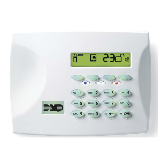
7360/7363 FEATURES Display Select Keys CODE RESET HOME EXIT CHIME PERIM SLEEP ZONE OUTPUT TEST INST Credential Reader Figure 1: Thinline Series Icon Keypad 7360/7363 Installation and Programming Guide Digital Monitoring Products, Inc. -
Page 7: Install The 7360/7363
INSTALL THE 7360/7363 Remove the Cover Insert a flat screwdriver into one of the slots on the bottom Cover of the keypad and gently lift the screwdriver handle toward you while pulling the halves Base apart. See Figure 2. Repeat with the other slot. -
Page 8: Wire The Keypad
Wire the Keypad The 7360 and 7363 keypads are supplied with a 4-wire harness for panel keypad bus connection. Since all 7300 Series keypads operate together on the Keypad bus using the same address, there is no address option to set. Observe wire colors when connecting the Red, Yellow, Green, and Black wires to the keypad bus. - Page 9 Digital Monitoring Products, Inc. 7360/7363 Installation and Programming Guide...
-
Page 10: Additional Information
ADDITIONAL INFORMATION Additional Power Supply If the current draw for all keypads exceeds the panel output, provide additional current by adding a Model 505-12 auxiliary power supply. Connect all keypad Black ground wires to the power supply negative terminal. Run a jumper wire from the power supply negative terminal to the panel common ground terminal. -
Page 11: Internal Speaker Operation
Police Emergency Fire TITLE SELECT KEYS ZONE NUMBER Panic Left Two Keys Emergency Center Two Keys Fire Right Two Keys Figure 4: Panic Keys Table 1: Panic Keys and Zones Internal Speaker Operation All keypads emit standard tones for key presses, entry delay and system alerts. The speaker also provides distinct burglary, fire, zone monitor and prewarn cadences. -
Page 12: Program The Keypad
PROGRAM THE KEYPAD End-User Options All models provide three keypad adjustments the end-user can make through the User Options Menu. Press and hold the Back Arrow and CMD keys for two seconds to access User Options. Use the CMD key to display the next option or press the Back Arrow to exit the User Options menu. -
Page 13: Internal Volume Level (L 8)
Internal Volume Level (L 8) Set the keypad internal speaker volume level for key presses and entry delay tone conditions from the range of off (0) to maximum (8). The far left position displays L (Level) and the far right position displays the selected volume level. -
Page 14: Installer Options Menu
Installer Options Menu All models provide a Keypad Option and Diagnostic menu to allow installing and service technicians to configure and test keypad operation. Since all 7300 Series keypads operate together on the Keypad bus using the same address, there is no address option to set. Accessing Installer Options The Installer Options Menu can only be accessed from the User Options menu while displaying the Software Version or Model Number. -
Page 15: Emergency Key (E 0)
Emergency Key (E 0) Use this option to configure the top two middle Select keys as 2-button Emergency keys. The display shows the current emergency key setting. The far left position displays E (Emergency)and the far right position displays the emergency key setting. -
Page 16: Keypad Diagnostics
Keypad Diagnostics LCD Segment Test At diagnostics startup the keyboard is backlit at maximum brightness and all the icons flash on and then off as a group. The keypad alternates between these two states for approximately two minutes. Press the Back Arrow to return to the Panic Keys option. Press CMD at any time to continue to the next test. -
Page 17: Keypad Bus Wiring Specifications
KEYPAD BUS WIRING SPECIFICATIONS • DMP recommends using 18 or 22-gauge unshielded wire for all keypad and AX-Bus/LX-Bus circuits. Do not use twisted pair or shielded wire for AX-Bus/LX-Bus and Keypad Bus data circuits. All 22-gauge wire must be connected to a power-limited circuit and jacket wrapped. •... -
Page 18: Product Specifications
Alarm 80 mA Thinline Dimensions 7.00 W x 5.25 H x 0.50 D in 17.78 W x 13.34 H x 11.30 D cm ORDERING INFORMATION 7360-W Thinline Series Icon Keypad, white 7363-W Thinline Series Icon Keypad with prox reader, white 7360/7363 Installation and Programming Guide Digital Monitoring Products, Inc. -
Page 19: Certifications
CERTIFICATIONS California State Fire Marshal (CSFM) FCC Part 15 ID: CCKPC0086 Industry Canada ID: 5251A-PC0086 Intertek (ETL) Listed ANSI/SIA CP-01 False Alarm Reduction ANSI/UL 1610 Central Station Burglar ANSI/UL 609 Local Burglar ANSI/UL 1076 Proprietary Burglar ANSI/UL 365 Police Connected Burglar ANSI/UL 1023 Household Burglar ANSI/UL 985... -
Page 20: Accessories
ACCESSORIES Backboxes Keypad Conduit Backbox Keypad Backbox Protective Keypad Cover Keypad Wiring Harness 4-wire Harness Proximity Credential for Use with Model 7363 1306P Prox Patch™ 1306PW Prox Patch™ 26-Bit 1326 HID ProxCard II® Card 1346 HID ProxKey II® Access Device ®... -
Page 21: Fcc Information
FCC INFORMATION This device complies with Part 15 of the FCC Rules. Operation is subject to the following two conditions: This device may not cause harmful interference, and This device must accept any interference received, including interference that may cause undesired operation. -
Page 22: Industry Canada Information
INDUSTRY CANADA INFORMATION This device complies with Industry Canada License-exempt RSS standard(s). Operation is subject to the following two conditions: This device may not cause interference, and This device must accept any interference, including interference that may cause undesired operation of the device. Le présent appareil est conforme aux CNR d’Industrie Canada applicables aux appareils radio exempts de licence. - Page 23 Digital Monitoring Products, Inc. 7360/7363 Installation and Programming Guide...
- Page 24 LT-0953 1.03 20175 © 2020 Digital Monitoring Products, Inc.
Need help?
Do you have a question about the Thinline Series and is the answer not in the manual?
Questions and answers