DMP Electronics Thinline 7060 Installation Manual
Lcd
Hide thumbs
Also See for Thinline 7060:
- Installation manual (29 pages) ,
- Installation sheet (11 pages) ,
- Quick manual (1 page)
Table of Contents
Advertisement
Models 7060A, 7063A, 7070A, 7073A
Power LED
Armed LED
Backlit Logo
and Proximity
Antenna
Thinline Keypad
7100 Series
InstallatIon GuIde
Thinline™ LCD Keypads
Models 7060, 7063, 7070, 7073,
7160, 7163, 7170, 7173
Aqualite™ LCD Keypads
32-Character Display
JONES RESIDENCE
FRI
12:51 PM
Data Entry Digit keys
Power LED
Armed LED
Thinline/Aqualite Keypads
Select Keys
COMMAND Key
Back Arrow Key
32-Character Display
ABC PRINTING
F R I
2 : 51 AM
1
2
3
4
5
6
7
8
9
0
CMD
Data Entry Digit keys
7000 Series
Select Keys
COMMAND Key
Back Arrow Key
Advertisement
Table of Contents

Subscribe to Our Youtube Channel
Related Manuals for DMP Electronics Thinline 7060


Summary of Contents for DMP Electronics Thinline 7060
- Page 1 InstallatIon GuIde Thinline™ LCD Keypads Models 7060, 7063, 7070, 7073, 7160, 7163, 7170, 7173 Aqualite™ LCD Keypads Models 7060A, 7063A, 7070A, 7073A 32-Character Display Power LED JONES RESIDENCE 12:51 PM Thinline/Aqualite Keypads Armed LED Select Keys 7000 Series Backlit Logo and Proximity Antenna COMMAND Key...
- Page 2 © 2013 Digital Monitoring Products, Inc. Information furnished by DMP is believed to be accurate and reliable. This information is subject to change without notice.
-
Page 3: Dmp Keypad Features
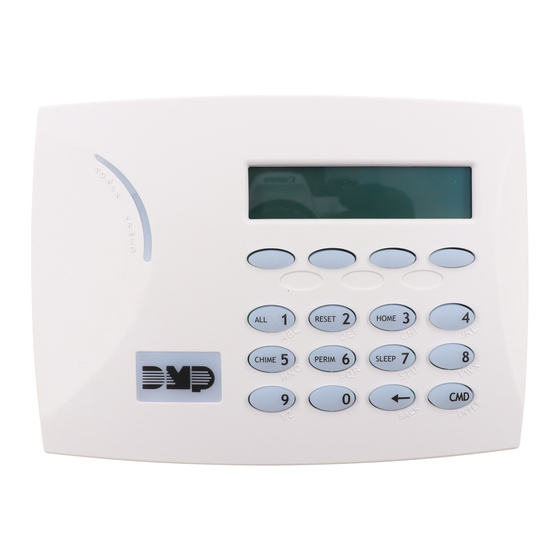
DMP Keypad Features The DMP Thinline™ and Aqualite™ LCD Keypads offer flexible features and functionality in stylish design choices. Each keypad provides: • Custom 16-character home or business name • Four 2-button Panic keys • AC power LED • Armed LED •... -
Page 4: Installing The Keypad
Installing the Keypad All DMP keypad housings are designed to easily install on any 4” square box, 3-gang switch box, DMP 695 and 696 backbox, or a flat surface. Figure 1 shows the keypad housing base mounting hole locations. Remove the Cover The keypad housing is made up of two parts: the front, which Building Wall contains the circuit board and keyboard components and the... -
Page 5: Keypad Bus Monitor
Surface and Backbox External Green/White – Connect Reader Data 0 Mounting Holes White – Connect Reader Data 1 Reader/ Orange – Door Strike Normally Open Door Strike Gray – Door Strike Common 7073/7073A Keypad Back Violet – Door Strike Normally Closed 7173 Keypads Yellow/White –... -
Page 6: Door Strike Relay Specifications
Green/White – Connect Reader Data 0 White – Connect Reader Data 1 Orange – Door Strike Normally Open Gray – Door Strike Common Violet – Door Strike Normally Closed Yellow/White – Zone 4 1K EOL White/Yellow Orange White – Zone 3 Request to Exit (option) 1K EOL White/Orange Red/White... -
Page 7: Panic Key Options 2-Button Panic Keys
Zone 2 Door Contact with Bypass If the door being released by the 7073/7073A/7173 keypad is protected, you can provide a programmed bypass time by connecting its contact to Zone 2 (White/Red pair) on the keypad and enabling the Bypass feature. See ZONE 2 BYPASS later in this document. -
Page 8: Internal Speaker Operation
Internal Speaker Operation All keypads emit standard tones for key presses, entry delay, and system alerts. The speaker also provides distinct burglary, fire, zone monitor, and prewarn cadences. The keypads provide an alternate prewarn with alarm cadence that occurs when the status list displays a zone alarm. -
Page 9: Entering Alpha Characters
Entering Alpha Characters To enter an alpha character, press the key that has the desired letter written below it. The keypad display shows the number on that key. To change the number to a letter, press the top row Select key that corresponds to the letter location under the key. -
Page 10: Programming Keypad Options
Programming Keypad Options Keypad Options (KPD OPT) Kpd Kpd To program keypad options, press the left Select key under Opt diag StOp KPD OPT. Keypad Address CUrrent Keypad Set the keypad address from 01 to 08 with the XT30, XT50, addreSS: XR100 or XR150 and 01 to 16 with the XR500 Series or XR350/XR550 Series. - Page 11 Zone 2 Bypass Time zOne 2 bypaSS (7073/7073A/7173 only) tiMe: Enter the number of Bypass seconds to elapse before the Bypass timer expires. Range is from 20 to 250 seconds. Press any top row select key to enter the number of seconds. Once the door strike relay is activated, the user has 5 seconds to open the door connected to zone 2.
- Page 12 Arming/Disarming Wait Time (7063/7063A, aLL?: nO yeS 7073/7073A, 7163/7173 only) deLay: Select the number of seconds (1-9) the keypad should wait when an area system displays ALL? NO YES during arming/ disarming or a HOME/SLEEP/AWAY system waits during arming only. If NO or YES, or HOME, SLEEP , or AWAY is not manually selected before the delay expires, the keypad automatically selects the YES or the AWAY key.
- Page 13 Site Code Position Site COde (7063/7063A, 7073/7073A, 7163/7173 only) pOSitiOn: Enter the site code start position in the data string. Press any Select key to enter a number between 0-255. Default is 1. Site Code Length Site COde (7063/7063A, 7073/7073A, 7163/7173 only) Length: Enter the number of characters the site code contains.
- Page 14 Site Codes 5-8 Site COdeS 5-8 (7063/7063A, 7073/7073A, 7163/7173 only) > > > > Enter site codes 5-8 (left to right separated by > sign). Press the Select key below the > sign to add, delete, or change the site code and press COMMAND. Site code range is 0-999. Number of User Code Digits nO OF USer COde (7063/7063A, 7073/7073A, 7163/7173 only)
-
Page 15: Exiting The Installer Options
Press the first Select key to choose LAST ChOOSe aCtiOn (Keep Last State) LaSt — The relay remains in the same state and does not change when communication is lost. After choosing the action, DEGRADED MODE and the newly defined action display. Programming is now complete. Accessing Keypad Diagnostics If necessary, refer to Access the Installer Menu earlier in this document. -
Page 16: Additional Programming
Additional Programming The 7063/7063A, 7073/7073A, and 7163/7173, keypads allow users to present a proximity credential to the built-in proximity reader. Users can also manually enter their user code into the keypad. The keypad verifies the user code and its authority with the panel. Additionally, the 7073/7073A/7173 activate the on-board Form C relay releasing a door strike or magnetic lock. -
Page 17: All/Perimeter System Arming And Disarming
ABC SECURITY ABC SECURITY ABC SECURITY ALL? ENTER CODE: – DISARM Select NO to arm or disarm individual areas. Select YES, or simply wait, to automatically arm or disarm all areas for which you are authorized. Figure 9: Area Arming and Disarming All/Perimeter System Arming and Disarming Present your card to the reader PERIM... -
Page 18: Fcc Information
Keypad Entry Delay All Systems Once the entry delay starts, the keypad sounds an entry tone and displays ENTER CODE: - . Present your card to the reader. Once validated, the system disarms all areas accessible by you and activates the 7073/7073A/7173 Door Strike relay. Area systems provide a delay to allow selected areas only to be disarmed. -
Page 19: Wiring Specifications For Keypad Bus
Wiring Specifications for Keypad Bus When planning a keypad bus installation, keep in mind the following specifications: 1. DMP recommends using 18 or 22-gauge unshielded wire for all keypad and LX- Bus circuits. Do Not use twisted pair or shielded wire for LX-Bus and keypad bus data circuits. -
Page 20: Specifications
Specifications Operating Voltage 12 VDC Thinline/Aqualite Dimensions 7” W x 5.25” H x 0.5” D Security Command Dimensions 6.5” W x 5” H x 1” D Compatibility All keypads are compatible with all DMP panels. Listings and Approvals California State Fire Marshall (CSFM) FCC Part 15 RFID Reader FCC ID: CCKPC0086 —...
Need help?
Do you have a question about the Thinline 7060 and is the answer not in the manual?
Questions and answers